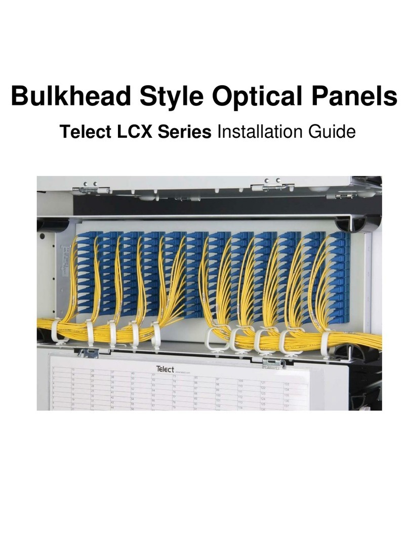
Telect LCX Series User manual

Telect Bulkhead-Style Optical Panels - LCX Series
User Manual

Page ii
Telect, Inc. • USA +1.509.926.6000 • Mexico +52.33.3836.37.52
www.telect.com • © 2010 Telect, Inc., All Rights Reserved, 126254-4 A0.1
Telect Bulkhead-Style Optical Panels - LCX Series
User Manual, Part Number 126254-4
Copyright 2010, Telect, Inc., All Rights Reserved
Telect and Connecting the Future are registered trademarks of Telect, Inc.
1730 N Madson St., Liberty Lake, Washington
Telect assumes no liability from the application or use of these products. Neither does Telect convey any
license under its patent rights nor the patent rights of others. This document and the products described
herein are subject to change without notice.
About Telect
Telect offers complete solutions for physical layer connectivity, power, equipment housing and other
network infrastructure equipment. From outside plantand central office to inside the home, Telect draws on
more than 25 years of experience to deliver leading edge product and service solutions. Telect is
committed to providing superior customer service and is capable of meeting the dynamic demands of
customer and industry requirements. This commitment to customer and industry excellence has positioned
Telect as a leading connectivity and power solution provider for the global communications industry.
Technical Support
E-mail: [email protected]
Phone: 888-821-4856 or 509-921-6161

Page iii
Telect, Inc. • USA +1.509.926.6000 • Mexico +52.33.3836.37.52
www.telect.com • © 2010 Telect, Inc., All Rights Reserved, 126254-4 A0.1
Telect Bulkhead-Style Optical Panels - LCX Series
User Manual
Table of Contents
Chapter 1: Description .............................................................................................................. 1
1.1 Overview .......................................................................................................................... 1
1.1.1 Features .................................................................................................................. 1
1.1.2 Capacities/Capabilities/Suitability ........................................................................... 2
1.1.3 Benefits ................................................................................................................... 2
1.1.4 Applications .............................................................................................................2
1.2 LCX Fiber Panels ............................................................................................................. 3
1.2.1 General Information ................................................................................................ 3
1.2.2 LCX Fiber Splice Panels..........................................................................................4
1.2.3 LCX Fiber Patch Panels ........................................................................................10
1.3 Special Function Modules ..............................................................................................13
1.4 Specifications ................................................................................................................. 14
1.4.1.Overall Dimensions ............................................................................................... 14
1.4.2 Environment .......................................................................................................... 14
1.4.3 Mounting ............................................................................................................... 14
1.4.4 Cable Compatibility ...............................................................................................15
1.4.5 Adapter Choices.....................................................................................................15
1.4.6 Optical Protections ................................................................................................15
1.4.7 Optical Performance ............................................................................................. 15
1.4.8 Compliance ........................................................................................................... 15
1.4.9 Certification ...........................................................................................................15
Chapter 2: Applications ........................................................................................................... 21
2.1 Interconnecting IFC to Network Elements ...................................................................... 21
2.2 Interconnecting Network Elements ................................................................................ 21
2.3 Cross-Connecting Network Elements ............................................................................ 22
2.4 Cross-Connecting Combinations ................................................................................... 22
2.5 Interconnecting & Cross-Connecting Along with
Special Function Modules .............................................................................................. 24
Chapter 3: Panel Installation ................................................................................................... 27
3.1 Installation Considerations ............................................................................................. 27
3.1.1 Location & Space .................................................................................................. 27
3.1.2 Tools & Equipment ................................................................................................ 27
3.1.3 Inspection ..............................................................................................................27

Page iv
Telect, Inc. • USA +1.509.926.6000 • Mexico +52.33.3836.37.52
www.telect.com • © 2010 Telect, Inc., All Rights Reserved, 126254-4 A0.1
3.2 Panel Installation (All Except 1RU) ................................................................................28
3.3 1RU Panel Installation ................................................................................................... 32
Chapter 4: Fiber Installation ................................................................................................... 35
4.1 Fiber Installation Overview ............................................................................................. 35
4.2 Fiber Installation Procedures (All Except 1RU) ..............................................................36
4.2.1 Splicing (All Except 1RU) ...................................................................................... 36
4.2.2 Patching (All Except 1RU) .....................................................................................41
4.3 1RU Fiber Installation ....................................................................................................42
4.3.1 1RU Splicing ......................................................................................................... 42
Chapter 5: Services ................................................................................................................. 47
5.1 Owner Maintenance ....................................................................................................... 47
5.2 Technical Support ..........................................................................................................47
5.3 In-Warranty Service .......................................................................................................47
5.4 Out of Warranty Service .................................................................................................47
5.5 Repacking for Shipment 48
5.6 High Insertion Loss and the Importance of
Cleaning Connectors & Adapters ................................................................................... 48
Chapter 6: Accessories ........................................................................................................... 49
6.1 Accessories and Replacement Parts .............................................................................49
List of Figures
Figure 1 - LCX Fiber Patch Panel (4RU) .....................................................................................1
Figure 2 - LCX Fiber Panels
(Common Physical Features of 2RU Through 4RU Panels) ........................................3
Figure 3 - LCX 1RU Fiber Panel.................................................................................................. 4
Figure 4 - 1RU Fiber Splice Tray ................................................................................................. 5
Figure 5 - 1RU Splice Tray (Right Corner Tray) .......................................................................... 5
Figure 6 - 1RU Splice Tray - Fiber Routing .................................................................................. 6
Figure 7 - 1RU Cable Clamp Fits 12 to 24 Fiber IFC ...................................................................6
Figure 8 - LCX Splice Panel, 2RU — 24 Termination Capacity ................................................... 7
Figure 9 - LCX Splice Panel, 3RU — 48 Termination Capacity ................................................... 7
Figure 10 - LCX Splice Panel, 4RU — 72 to 96 Termination Capacity ........................................ 8
Figure 11 - Splice Tray (Right Corner View) ................................................................................8
Figure 12 - Splice Tray (Fiber Routing) ........................................................................................9
Figure 13 - Optional Cable Clamp Fits All Sizes of IFC ...............................................................9
Figure 14 - LCX Patch Panel, 1RU — 12 Termination ..............................................................10
Figure 15 - LCX Patch Panel, 2RU — 24 Termination ..............................................................11
Figure 16 - LCX Patch Panel, 3RU — 48 Termination ..............................................................11

Page v
Telect, Inc. • USA +1.509.926.6000 • Mexico +52.33.3836.37.52
www.telect.com • © 2010 Telect, Inc., All Rights Reserved, 126254-4 A0.1
Figure 17 - LCX Patch Panel, 4RU — 72, 96, or 144 Termination ............................................12
Figure 18 - Patch Plates ............................................................................................................ 12
Figure 19 - WDM & Splitter Modules .........................................................................................13
Figure 20 - 1RU LCX Chassis ....................................................................................................16
Figure 21 - 2RU LCX Chassis ....................................................................................................17
Figure 22 - 3RU LCX Chassis ....................................................................................................18
Figure 23 - 4RU LCX Chassis ...................................................................................................19
Figure 24 - Pull-Out & Swing-Out Clearances ........................................................................... 20
Figure 25 - Interconnecting/Splicing Facility Cable to Network Elements .................................. 21
Figure 26 - Interconnecting Network Elements in a LCX Fiber Patch Panel .............................21
Figure 27 - Cross-Connecting Network Elements ...................................................................... 22
Figure 28 - Cross-Connecting IFC to Network Elements ...........................................................23
Figure 29 - Interconnecting/Cross-Connecting Along with WDM/Splitter Modules .................... 25
Figure 30 - Removing Knockouts & Installing Plastic Grommets ............................................... 28
Figure 31 - Installing a Standard Split Arc .................................................................................29
Figure 32 - Installing a Standard Isolation Hook Kit ...................................................................29
Figure 33 - Installing An Optional Arc Kit ...................................................................................30
Figure 34 - Mounting LCX Panel to Rack ..................................................................................30
Figure 35 - Installing Adapter Pack & Special Function Modules .............................................. 31
Figure 36 - Inserting Cabling Rings ..........................................................................................31
Figure 37 - Cable Restraint Layout (Top View of Chassis Bottom) ...........................................32
Figure 38 - Mounting 1RU LCX Panel to Rack ..........................................................................32
Figure 39 - Mounting 1RU LCX Combo Panels to Rack ............................................................33
Figure 40 - Installing Patch Plates & Special Function Modules in a 1RU ................................. 33
Figure 41 - IFC Breakout Length (2RU through 4RU) ...............................................................36
Figure 42 - IFC Clamp ............................................................................................................... 37
Figure 43 - Installing IFC for Splicing ......................................................................................... 37
Figure 44 - Cable Placement and Securing ...............................................................................38
Figure 45 - Splice Tray (Right Corner View) ............................................................................. 39
Figure 46 - Splice Tray (Fiber Routing) ......................................................................................40
Figure 47 - Installing Interconnects or Cross-Connects in an LCX Fiber Patch Panel .............. 41
Figure 48 - IFC Breakout Length (1RU) .....................................................................................42
Figure 49 - Installing an IFC for a LCX 1RU Panel.................................................................... 43
Figure 50 - Cable Routing .......................................................................................................... 44
Figure 51 - 1RU Splice Tray (Right Corner Tray) ......................................................................45
Figure 52 - 1RU Splice Tray (Fiber Routing) ............................................................................. 45
Figure 53 - Cleaning the Adapter ...............................................................................................48

Telect, Inc. • USA +1.509.926.6000 • Mexico +52.33.3836.37.52
www.telect.com • © 2010 Telect, Inc., All Rights Reserved, 126254-4 A0.1
Page 1-1
Chapter 1: Description
1.1 Overview
Telect’s LCX Patch/Splice
Panel Systems provide inter-
connectivity and cross-
connectivity of riser/plenum
and network element fiber
cabling. Panels provide a
central location for patching,
splicing, testing,
troubleshooting, monitoring,
and restoring service to fiber-
optic systems.
LCX panels fit standard 19-
and 23-in. (EIA/WECO
spacing) and ETSI racks.
4RU panels support up to 144 terminations.
LCX Patch Panels and Splice Panels provide a total solution as well as standalone splice and
patch capabilities. All Telect LCX panels are system compatible with standard LGX® style
panels, thereby serving as replacements or add-ons in system solutions of other manufacturers.
Patch adapter terminations include SC/UPC and APC, and FC/UPC and APC, LC/UPC,
and ST/UPC.
LCX Patch Panels are available with or without fiber adapters. Telect offers patch plates with 6,
8, or 12 adapters per plate for on-site configuration. The 1RU through 4RU LCX Patch Panels
also accept standard Wavelength Division Multiplexing (WDM), splitter, and monitor modules.
1.1.1 Features
Telect manufactures LCX Patch Panels and Splice Panels to suit any system architecture.
Features include
• Design for compliance (fiber bend-radius control, flammability safety, structural reliability).
NEBS 3 and ETSI certification
• Zone 4 Seismic reliability
• Light weight
• Easy removal of splice tray for rapid termination of cable
• No cassette requirement. Removable trays provide for easy and direct storage and splicing.
• Easy access via removable front and rear doors or bi-directional sliding drawer
Figure 1 - LCX Fiber Patch Panel (4RU)

Telect, Inc. • USA +1.509.926.6000 • Mexico +52.33.3836.37.52
www.telect.com • © 2010 Telect, Inc., All Rights Reserved, 126254-4 A0.1
Page 1-2
1.1.2 Capacities/Capabilities/Suitability
• LCX panels are available for universal 19-in., 23-in., and ETSI racks.
• You can have 12, 24, 48, 72, 96, or 144 (LC) termination capacities per panel (1RU through
4RU) using site-installed patch plates. There are up to 144 per panel with factory-installed
discrete adapters.
• Standard-size 6, 8, or 12 adapters are available per patch plate for on-site patch panel adap-
tation of empty panels.
• SC/UPC, SC/APC, FC/UPC, FC/APC, LC/UPC, and ST/UPC patch plates are available.
• Standard-size Wavelength Division Multiplexing (WDM) and splitter modules can be used
along with adapter packs for added flexibility.
• All LCX Patch/Splice Panels are fully compatible with standard LGX® style panels for IFC
entrance, splicing, and network patching architecture.
• All LCX panels are compatible with Telect’s WaveTrax cable management systems, as well
as those of other manufacturers.
• 2RU through 4RU models include slip-on, split arcs for patch cord entrance; optional cable
management kits are available to suit operating company preferences.
1.1.3 Benefits
Telect’s LCX Splice/Patch Panels are ideal for central office, head-end and wiring centers.
Benefits include
• Low cost — High Fiber Density — Versatility
• Easy Installation
• Compatibility
• Simple, straight-forward cable management, access, circuit identification, and isolation
• Easy access to riser/network/patch cord connections
1.1.4 Applications
•CATV
•MTSO
• Outside plant
• Central Office
• Optical distribution/cross-connect

Telect, Inc. • USA +1.509.926.6000 • Mexico +52.33.3836.37.52
www.telect.com • © 2010 Telect, Inc., All Rights Reserved, 126254-4 A0.1
Page 1-3
1.2 LCX Fiber Panels
1.2.1 General Information
Telect manufactures LCX Fiber Splice Panels and LCX Fiber Patch Panels of various densities
to suit company-wide fiber splice, patching, and routing requirements.
All LCX Fiber Panels are white or black metal chassis in various sizes (1RU through 4RU)
accommodating various fiber densities. All panels (2RU - 4RU) come equipped with front and
rear metal doors. All include cable entry/exit points near the panels’ four corners:
• 2RU through 4RU models vary in density from 24 to 144 fiber terminations. All have spring-
hinged removable front and rear doors, as shown in Figure “LCX Fiber Panels (Common
Physical Features of 2RU Through 4RU Panels)” on page 3. Knock-out holes at the top and
bottom of the panel allow for routing from splice panels to patch panels (and between patch
panels) vertically within the rack. Hole pattern and positions are compatible with panels
offered by other manufacturers, allowing expansion and replacement of those systems using
Telect’s low-cost LCX panels.
• Interconnection and cross-connection cabling from above or below enter at the two front cor-
ners of each Telect LCX panel via isolation hooks and/or radius control arcs installed on-site
to suit the application and entry/exit direction. Eight split arcs and fourteen snap-in cable rings
are standard with each panel. Telect also offers two optional kits to satisfy cable manage-
ment practices requiring multiple arcs or guide posts to separate and isolate groups of
fiber cables.
• 1RU models have densities up to 24 fiber terminations. Instead of front and rear doors, 1RUs
have a removable sliding drawer that can be extended at the front or rear of the chassis to
maximize access to fiber connections. Pivoting arcs at corner entries and exits provide cable
Figure 2 - LCX Fiber Panels
(Common Physical Features of 2RU Through 4RU Panels)

Telect, Inc. • USA +1.509.926.6000 • Mexico +52.33.3836.37.52
www.telect.com • © 2010 Telect, Inc., All Rights Reserved, 126254-4 A0.1
Page 1-4
management. Entry and exit positions are compatible with entries and exits of other Telect
LCX panels and those of other manufacture.
1.2.2 LCX Fiber Splice Panels
Telect offers four sizes of LCX Fiber Splice Panels (1RU through 4RU) to accommodate up to
144 splices.
Each removable splice tray holds up to 24 splices along with 1½ m of fiber cable storage:
• For a 1RU splice tray, all fiber (subunit, cable, and strands) is stored on the tray.
• For a 2RU, 3RU or 4RU splice tray, all subunit and interconnection cable storage is below
the trays.
Trays easily slip free of the panels to allow splicing. Storage spools or arcs, along with splice
holders, are mounted directly on the tray, eliminating the need for special splice cassettes.
Figure 3 - LCX 1RU Fiber Panel

Telect, Inc. • USA +1.509.926.6000 • Mexico +52.33.3836.37.52
www.telect.com • © 2010 Telect, Inc., All Rights Reserved, 126254-4 A0.1
Page 1-5
1.2.2.1 LCX 1RU Fiber Splice Trays - 24-Splice Capability
Figure 4 - 1RU Fiber Splice Tray
LCX 1RU Fiber Splice Trays use sets of pivoting arcs for routing and storing both fiber subunits
and interconnection cable.
Arcs (14)
Each of Two Splice Holders
Holds 12 Splices
Splice Cover
Figure 5 - 1RU Splice Tray (Right Corner Tray)

Telect, Inc. • USA +1.509.926.6000 • Mexico +52.33.3836.37.52
www.telect.com • © 2010 Telect, Inc., All Rights Reserved, 126254-4 A0.1
Page 1-6
IFC stranded cable from the splice vault is secured at either rear corner of the LCX Splice Panel
by an optional cable clamp. (A single clamp comes with two rubber bushings to fit either a 12- or
24-fiber IFC riser/plenum cable.) The following illustration shows a clamp holding an IFC cable
installed on the rear rack flange near the entry/exit of an LCX 1RU Splice Panel. The
interconnection cables enter the tray at one of the other corners of the splice tray.
Figure 7 - 1RU Cable Clamp Fits 12 to 24 Fiber IFC
Tie-Down for Cable Ties*
Tie-Down for Cable Ties*
From
IFC
To Network
Elements * Use either lacing or cable ties to secure cable subunit,flexible tubing, and/or sheathing.
Figure 6 - 1RU Splice Tray - Fiber Routing
Cable Clamp
24-Fiber IFC
Network Cable
Leave sufficient
slack to allow drawer
to open.

Telect, Inc. • USA +1.509.926.6000 • Mexico +52.33.3836.37.52
www.telect.com • © 2010 Telect, Inc., All Rights Reserved, 126254-4 A0.1
Page 1-7
1.2.2.2 LCX 2RU, 3RU, & 4RU Fiber Splice Trays
The following figures show termination capacities of the LCX 2RU, 3RU,and 4RU Fiber Splice
Panels. A 144-splice, 4RU LCX panel accommodating 4 splice trays is available but not pictured.
• 24-splice, 2RU LCX panel accommodates 1 splice tray
• 48-splice, 3RU LCX panel accommodates 2 splice trays
• 72-splice, 4RU LCX panel accommodates 3 splice trays
• 96-splice, 4RU LCX panel accommodates 4 splice trays
2RU, 3RU, and 4RU Fiber Splice Trays use storage spools to route and store stranded fiber.
Figure 8 - LCX Splice Panel, 2RU — 24 Termination Capacity
Figure 9 - LCX Splice Panel, 3RU — 48 Termination Capacity

Telect, Inc. • USA +1.509.926.6000 • Mexico +52.33.3836.37.52
www.telect.com • © 2010 Telect, Inc., All Rights Reserved, 126254-4 A0.1
Page 1-8
Figure 10 - LCX Splice Panel, 4RU — 72 to 96 Termination Capacity
Figure 11 - Splice Tray (Right Corner View)

Telect, Inc. • USA +1.509.926.6000 • Mexico +52.33.3836.37.52
www.telect.com • © 2010 Telect, Inc., All Rights Reserved, 126254-4 A0.1
Page 1-9
IFC stranded cable from the splice vault is secured at either rear corner of the LCX Splice Panel
by an optional cable clamp. (A single clamp fits all sizes of IFC riser and plenum cable.) Figure
13 on the following page shows a clamp holding a 96-strand IFC cable installed at the left rear
corner of an LCX Splice Panel. Cable rings in the rear portion of the panel lead the IFC tubes to
one of the front corners of the splice trays. The interconnection cables enter the tray at the other
front corner of the 2RU/3RU/4RU splice tray.
Tie-Down Locations for Cable Ties
To Network Elements * Strands are always routed clockwise on the left spool and counter-clockwise on the right spool.
Pigtail from NE is wound around
From IFC
the other spool.*
around one of the spools...
Stranded fiber from IFC is wound
Figure 12 - Splice Tray (Fiber Routing)
Cable Clamp
96-Fiber IFC
Figure 13 - Optional Cable Clamp Fits All Sizes of IFC

Telect, Inc. • USA +1.509.926.6000 • Mexico +52.33.3836.37.52
www.telect.com • © 2010 Telect, Inc., All Rights Reserved, 126254-4 A0.1
Page 1-10
1.2.3 LCX Fiber Patch Panels
LCX Fiber Patch Panels come in six termination capacities and can be loaded with various patch
plates. See Figures 14 - 17.
In addition to patch panels with or without installed patch plates, Telect offers a special factory-
configured 4RU patch panel with 144 discrete SC/UPC adapters.
All panels can accommodate SC/UPC, SC/APC, FC/UPC, FC/APC, LC/UPC, or ST/UPC patch
plates. Patch plates simply snap into the chassis’ bulkhead:
• SC/UPC, SC/APC, FC/UPC, FC/APC and ST/UPC are available in patch plates with six or
eight adapters.
• LC/UPC is available in patch plates with 12 adapters.
All adapters include dust covers. Like the chassis, most patch plates are available in white or
black. See Figure 18.
Figure 14 - LCX Patch Panel, 1RU — 12 Termination

Telect, Inc. • USA +1.509.926.6000 • Mexico +52.33.3836.37.52
www.telect.com • © 2010 Telect, Inc., All Rights Reserved, 126254-4 A0.1
Page 1-11
Figure 15 - LCX Patch Panel, 2RU — 24 Termination
Figure 16 - LCX Patch Panel, 3RU — 48 Termination

Telect, Inc. • USA +1.509.926.6000 • Mexico +52.33.3836.37.52
www.telect.com • © 2010 Telect, Inc., All Rights Reserved, 126254-4 A0.1
Page 1-12
Figure 17 - LCX Patch Panel, 4RU — 72, 96, or 144 Termination
6-Adapter Patch Plate (SC, FC, ST)
8-Adapter Patch Plate (SC, FC, ST)
12-Adapter Patch Plate (LC Only)
Figure 18 - Patch Plates

Telect, Inc. • USA +1.509.926.6000 • Mexico +52.33.3836.37.52
www.telect.com • © 2010 Telect, Inc., All Rights Reserved, 126254-4 A0.1
Page 1-13
1.3 Special Function Modules
Empty LCX Fiber Patch Panels can be configured on-site with adapter packs and special
function modules.
Telect offers a full line of standard-size Wavelength Division Multiplexing (WDM) modules and
splitter modules that can be used in place of adapter packs. Some special-function Telect
modules are illustrated below. Call Telect at 1-509-926-6000, 1-800-551-4567 (domestic). See
Telect.com for detailed information.
Figure 19 - WDM & Splitter Modules

Telect, Inc. • USA +1.509.926.6000 • Mexico +52.33.3836.37.52
www.telect.com • © 2010 Telect, Inc., All Rights Reserved, 126254-4 A0.1
Page 1-14
1.4 Specifications
1.4.1.Overall Dimensions
• Dimensions: See the drawings (Figure 20 through 24) following these specifications for
access and fit.
• Patch Chassis Weight (without adapters, patch plates, or cabling):
• Splice Chassis Weight (without cabling or trays, except as noted):
• 2RU, 3RU, & 4RU Splice Tray Weight (without cabling):
• 1RU Chassis and Tray Material & Finish: .060 cold-rolled steel. Finish is either powder-
coat white or black.
• 2RU, 3RU, & 4RU Chassis and Tray Material & Finish: Cold-rolled .080 aluminium for all
but bottom. Bottom is .060 cold-rolled steel. Finish is either powder-coat white or black.
• Black Tray Components: 94 V0 PC/ABS black plastic
• Splice Cover: Transparent polycarbonate.
1.4.2 Environment
• Ambient Temperature: -5°C to 55°C (23°F to 131°F)
• Relative Humidity: 0% to 90% and noncondensing
1.4.3 Mounting
• 19-in. or 23-in. with ETSI, EIA, or WECO spacing.
Patch Assemblies Weight (lb) Weight (kg)
1RU 5.0 2.27
2RU 6.0 2.72
3RU 7.0 3.18
4RU 8.0 3.63
Splice Assemblies Weight (kg) Weight (lb)
1RU (with one splice tray) 5.0 2.27
2RU (with one splice tray) 6.0 2.72
3RU 7.0 3.18
4RU 8.0 3.63

Telect, Inc. • USA +1.509.926.6000 • Mexico +52.33.3836.37.52
www.telect.com • © 2010 Telect, Inc., All Rights Reserved, 126254-4 A0.1
Page 1-15
1.4.4 Cable Compatibility
•250µmOSP
• 900 µm IFC
• 1.75 mm, 2 mm, and 3 mm patch cords and jumpers (Simplex or Duplex)
1.4.5 Adapter Choices
• SC/UPC and APC in 6- and 8-position patch plates
• FC/UPC and APC in 6- and 8-position patch plates
• LC/UPC in 12-position patch plates only
• ST/UPC in 6- and 8-position patch plates only
1.4.6 Optical Protections
• Bend Radius: >30 mm throughout for all cable routing
• Eye Protection: All adapters have factory-installed dust covers.
1.4.7 Optical Performance
LCX will not influence signal timing or jitter.
1.4.8 Compliance
NEBS, ETSI, Zone 4 seismic reliability
1.4.9 Certification
UL 60950, CE EN 60950, Bellcore GR-63-CORE, Bellcore GR-1089-CORE,
ETSI EN 300 019-2-(1,2,3)
Other manuals for LCX Series
1
Table of contents
Other Telect Control Panel manuals
Popular Control Panel manuals by other brands

Setra Systems
Setra Systems SRPM Installation and operating manual
Mitsubishi Electric
Mitsubishi Electric GOT SIMPLE GS2110-WTBD user manual
Bosch
Bosch FPD-7024 operating instructions
AUTOTERM
AUTOTERM PU-5 operating manual
BFT
BFT Rigel 6 QRG Quick reference guide
enware
enware Custodian CN2DF-FF Installation and maintenance instructions
SALUPO
SALUPO SOFT START PLUS 1 Instruction and installation manual
GST
GST 852RPX Installation and operation manual

Honeywell
Honeywell ENVIRAZONE PANEL W8835 Product data
Toro
Toro SENTINEL SATELLITE Quick reference guide
Eaton
Eaton Greengate ControlKeeper CK4A-SSRC installation instructions
Casals
Casals CTRL-DPH User manual and instructions
