Telect 009-8004-0208 User manual

8x8 KLM / GMT Power Distribution Panel
Model 009-8004-0208
Installation Guide

Page ii
Telect, Inc. • USA +1.509.926.6000 • Mexico +52.33.3836.37.52
www.telect.com • © 2010 Telect, Inc., All Rights Reserved, 117200-4 A0
8x8 KLM / GMT Power Distribution Panel
Model 009-8004-0208
Installation Guide, Part Number 117200-4
Copyright 2010, Telect, Inc., All Rights Reserved
Telect and Connecting the Future are registered trademarks of Telect, Inc.
1730 N Madson St., Liberty Lake, Washington
Telect assumes no liability from the application or use of these products. Neither does Telect convey any
license under its patent rights nor the patent rights of others. This document and the products described
herein are subject to change without notice.
About Telect
Telect offers complete solutions for physical layer connectivity, power, equipment housing and other
network infrastructure equipment. From outside plant and central office to inside the home, Telect draws on
more than 25 years of experience to deliver leading edge product and service solutions. Telect is
committed to providing superior customer service and is capable of meeting the dynamic demands of
customer and industry requirements. This commitment to customer and industry excellence has positioned
Telect as a leading connectivity and power solution provider for the global communications industry.
Technical Support
E-mail: getinfo@telect.com
Phone: 888-821-4856 or 509-921-6161

Telect, Inc. • USA +1.509.926.6000 • Mexico +52.33.3836.37.52
www.telect.com • © 2010 Telect, Inc., All Rights Reserved, 117200-4 A0
Page iii
8x8 KLM / GMT Power Distribution Panel
Model 009-8004-0208
Installation Guide
Table of Contents
1.1 Introduction ............................................................................................................................ 1
1.2 Specifications ......................................................................................................................... 1
1.3 Inspection ............................................................................................................................... 3
1.4 Installation .............................................................................................................................. 4
1.4.1 Installing and grounding the panel ................................................................................4
1.4.2 Connecting Input Power ................................................................................................ 5
1.4.3 Connecting to the Power Bays ...................................................................................... 6
1.4.4 Supplying & Testing Input Power ..................................................................................6
1.4.5 Testing the Input Power Alarm Relays ..........................................................................6
1.4.6 Connecting Output Cables ............................................................................................ 7
1.5 General Guidelines for Installing Fuses .................................................................................8
1.5.1 Installing KLM Fuses .....................................................................................................8
1.5.2 Installing GMT Fuses ....................................................................................................9
1.5.3 Testing the Fuse Alarm Relays ..................................................................................... 9
1.5.4 Fuse Alarm Visual Indicator Test ..................................................................................9
1.6 Powering the Load Equipment .............................................................................................10
1.7 Replacing the Alarm Card .................................................................................................... 11
1.8 Replacing Fuses .................................................................................................................. 11
1.9 Service ................................................................................................................................. 12
1.9.1 In-Warranty Service .................................................................................................... 12
1.9.2 Out-Of-Warranty Service ............................................................................................12
1.10 Accessories and Kits .......................................................................................................... 12
1.11 Reference Schematic ......................................................................................................... 14
1.12 Physical Attributes ............................................................................................................. 15

Page iv
Telect, Inc. • USA +1.509.926.6000 • Mexico +52.33.3836.37.52
www.telect.com • © 2010 Telect, Inc., All Rights Reserved, 117200-4 A0
List of Figures
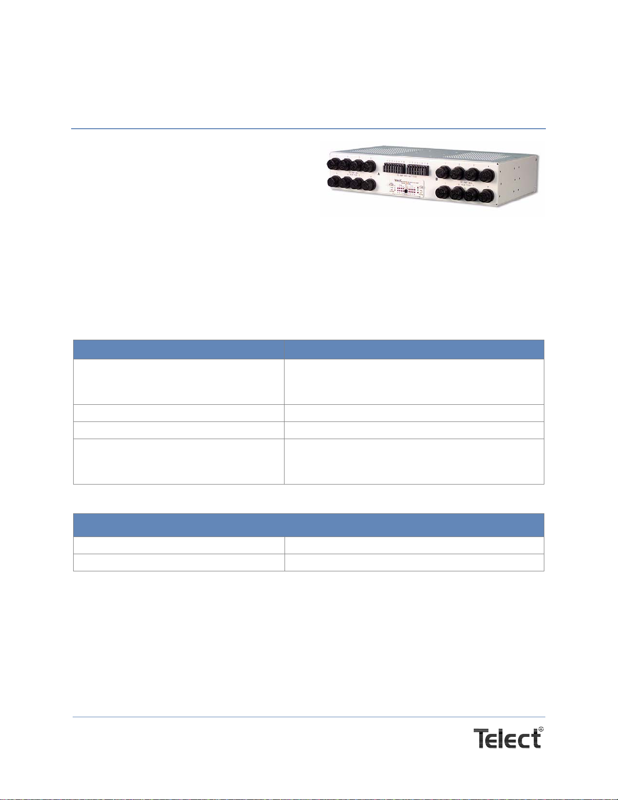
Figure 1 - Model 009-8004-0208 .................................................................................................1
Figure 2 - Grounding .................................................................................................................... 4
Figure 3 - Power connection ........................................................................................................ 5
Figure 4 - Test Guide.................................................................................................................... 6
Figure 5 - Connecting Output Cables .......................................................................................... 7
Figure 6 - Fuse Alarm Card ......................................................................................................... 9
Page 1
Telect, Inc. • USA +1.509.926.6000 • Mexico +52.33.3836.37.52
www.telect.com • © 2010 Telect, Inc., All Rights Reserved, 117200-4 A0
8x8 KLM / GMT Power Distribution Panel
Model 009-8004-0208 Installation Guide
1.1 Introduction
Please read these instructions carefully before
beginning installation. If you need assistance, call
Technical Support at 1-888-821-4856 (domestic
calls), or 509-921-6161 (Option 2), or email us at
Panel brackets provide either flush or extended
mounting in an EIA or WECO rack. The panel is configured at the factory for extended mounting
in a 19" rack. ETSI mounting kits are also available; contact Telect or your distributor.
Model 009-8004-0208 is UL Listed, File E139903, and NEBS Certified.
1.2 Specifications
Physical
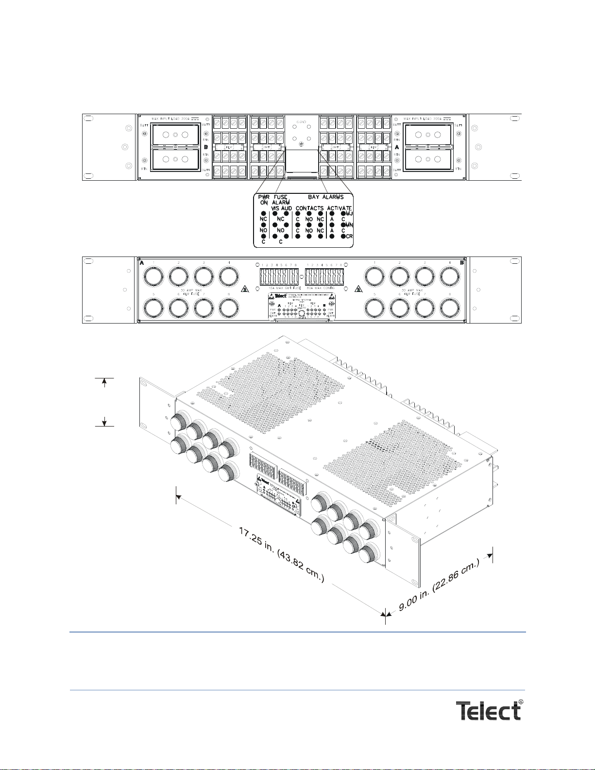
Dimensions, with brackets Width: 17.50 in. (44.45 cm)
Height: 3.47 in. (8.81 cm)
Depth: 9.00 in. (22.86 cm)
Weight, without fuses 13.5 lbs. (6.12 kg.)
Weight, shipping 15 lbs. (6.8 kg.)
Mounting capability:
(ETSI brackets sold separately) EIA: 19-inch (48.26 cm)
WECO: 23-inch (58.42 cm)
ETSI: Kits sold separately.
Environmental
Temperature range, ambient -17°C to 49°C (0°F to 120°F)
Humidity 0% to 90% and noncondensing
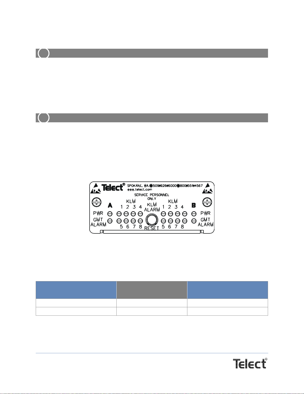
Figure 1 - Model 009-8004-0208

Page 2
Telect, Inc. • USA +1.509.926.6000 • Mexico +52.33.3836.37.52
www.telect.com • © 2010 Telect, Inc., All Rights Reserved, 117200-4 A0
Mechanical
Ground terminals Quantity: 2
Stud size: 10-24
Nut: 10-24 KEPS
Socket size: 3/8 inch (10 mm)
Cable: Min. #4 at 250A input rating
Lugs: 2-hole compression lug
Size: Same as input cable: #6 up to 2 AWG
Center to center: 5/8 inch (1.59 cm)
Maximum torque: 20 in-lb (2.26 N•m)
Input terminals Quantity: 4: 2 BATT, 2 RTN
Stud size: 5/16-18
Nut: 5/16-18 KEPS
Socket size: 1/2 inch (13 mm)
Cable: #8 AWG to 4/0 AWG
Lugs: 2-hole compression lug
Size: Same as cable up to 4/0 AWG -
rated to input fuse size
Center to center: 1 inch (2.54 cm)
Maximum torque: 60 in-lb. (6.78 N•m)
Alarm terminals: wire-wrap Quantity: 24
Cable: 22-26 AWG
Output terminals Quantity: 32: 16 BATT, 16 RTN
Screw size: #8-32 wire-clamping
Cable: #22 to #10 AWG - rated to output fuse size
Maximum torque: 9 in-lb (1.01 N•m)
Output Terminal maximum lug width: 5/16 in. (0.79 cm.)
GMT fuse Insertion/Withdrawal force Insertion: 7lbs. +/- 3.1lbs. (3.18 kg. +/- 1.41 kg.)
Withdrawal: 5.5 lbs. +/- 2.5 lbs. (2.49 kg. +/- 1.13 kg.)
KLM fuse Insertion/Withdrawal force Maximum Average force: 12 lbs
Electrical
Operating voltages -20 to -60 VDC, +20 to +30 VDC
Maximum input interruption device rating 250A per side
Maximum continuous input load rating @ 80%
input interruption device rating 250A interruption device for 200A per side or less with
80% rule
Maximum output interruption device rating 30A per KLM fuse, 15A per GMT fuse
Maximum continuous output load rating @ <
80% interruption device rating 25A max. continuous load per KLM position. 12A max.
continuous load per GMT fuse position.
Page 3
Telect, Inc. • USA +1.509.926.6000 • Mexico +52.33.3836.37.52
www.telect.com • © 2010 Telect, Inc., All Rights Reserved, 117200-4 A0
1.3 Inspection
Inspect equipment after unpacking and compare it to the packing list.
Immediately report any shipping damage, defects, or missing parts to Telect at 1-800-551-4567.
Keep all documentation that comes with your shipment.
Telect is not liable for shipping damage. If the product is damaged, notify the carrier and call
Telect’s Customer Service Department at 1-800-551-4567 (domestic only) or 1-509-926-6000 for
further recourse.
NOTE: For service or warranty information, please visit telect.com website, or email inquiries to
getinfo@Telect.com and click on the “Support” tab, or phone us at 800-551-4567 (domestic only)
or 509-926-6000.
Alarm contact ratings, continuous 2A at 30 VDC
0.6A at 60 VDC
1A at 120 VAC
Alarm board power ratings @20V: 100 mA (2 W)
@24V: 153 mA (3.672 W)
@27V: 166 mA (4.48 W)
@30V: 167 mA (5.01 W)
@42V: 173 mA (7.27 W)
@48V: 175 mA (8.4 W)
@56V: 179 mA (10.02W)
@60V: 181 mA (10.86 W)
Max. operating temperature at max.
load ratings 55°C (131°F)
Min. operating temperature at max. load ratings -10°C (14°F)
Ambient operating temp. at half-load 72°C (162°F)
Max. surface temperature of fuses at 26°C
(79°F) ambient Front face: 59°C (138°F)
Top/Bottom face: 91°C (196°F)
Max. panel heat dissipation @ full load 80W per side for 8, 20A KLM fuses
26W per side for 8, 12A GMT fuses
Panel heat dissipation @ typical load Less than 100W per side
Electrical
Page 4
Telect, Inc. • USA +1.509.926.6000 • Mexico +52.33.3836.37.52
www.telect.com • © 2010 Telect, Inc., All Rights Reserved, 117200-4 A0
1.4 Installation
ALERT
!
ALERT! Install this product within a restricted access location where access is through
the use of a tool, lock and key, or other means of security, and is controlled by the
authority responsible for the location. Only qualified technicians may install and maintain
this product.
Mount the panel to the upper-most rack position, if possible. Allow one rack unit of empty space
(1.75 inches or 4.45 cm) below the panel to provide adequate ventilation.
CAUTION
!
CAUTION! Failure to properly ground this equipment can create hazardous conditions to
installation personnel and to the equipment!
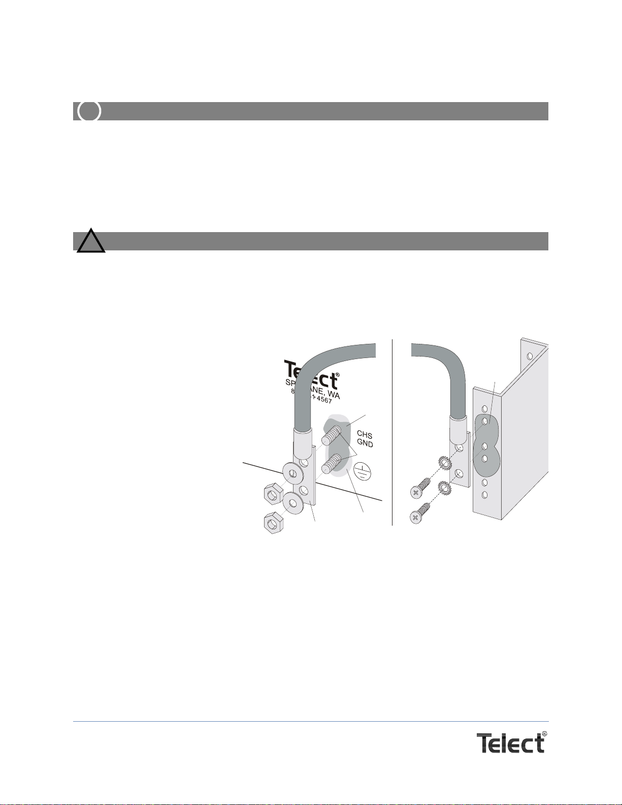
1.4.1 Installing and grounding the panel
1. Clean all contact surfaces.
2. Mount the panel using the
four screws and star wash-
ers provided.
3. Tighten the screws to 35 in-
lb (4.29 N•m).
4. Secure the compression lug
to the grounding studs with
the10-24hexnutsprovided.
5. Torque the nuts to 20 in-lb
(2.26 N•m) with a 3/8-inch
(10 mm) socket.
6. Attach the ground cable(s)
to the ground relay rack or
ground bus according to the
operating company’s instal-
lation procedures.
7. Label the front and the rear of the panel according to the labeling conventions specified in
Telect‘s Wire Sizing and Label Chart (117995).
GROUND TO CHASSIS
Earth-ground
studs
Compression
lug
Torque 1/4
nuts to 25 in-lb (2.84 N-m)
–20 HEX
GROUND TO RACK OR BUS
Anti-oxidant
compound
Remove paint
for surface area contact
and apply anti-oxidant
(recommended)
Torque screws and washers
to 25 in-lb (2.84 N-m)
Anti-oxidant
compound
Figure 2 - Grounding

Page 5
Telect, Inc. • USA +1.509.926.6000 • Mexico +52.33.3836.37.52
www.telect.com • © 2010 Telect, Inc., All Rights Reserved, 117200-4 A0
1.4.2 Connecting Input Power
DANGER
!
DANGER! Before connecting input power cables, SHUT DOWN PDF (Primary Distribution
Frame) POWER to the circuits feeding the KLM-PDP. Remove or lock out the PDF circuit
breakers, or verify that the PDF fuse positions are open. Failure to do so can result in haz-
ardous conditions!
NOTE: Input power cables connect the KLM-PDP to the PDF. The cables must support 125% of
the rated, continuous load current of the equipment powered by the KLM-PDP fuses. The
maximum continuous load is 200 amps per side. Keep plastic contact covers in place when
not changing leads.
1. Make sure the input power is OFF.
2. Construct BATT and RTN cables for both A and B input power circuits. Use properly rated ca-
bles and two-hole compression lugs. The cables may require 45° or 90° lugs.
3. Insulate the lug barrels with UL94V0-rated
heat shrink tubing, as shown. It may be
necessary to cover the lug inspection hole
with the tubing.
4. For assistance, refer to the operating com-
pany’s installation procedures.
5. Locate the two input power terminals (Input
A and Input B) on the KLM-PDP backplane.
6. Remove the black plastic terminal covers,
and remove the knockout if using 45°
or 90° lugs.
7. Remove any sharp edges.
8. Use a coarse, non-metallic cleaning pad to
clean the contact areas of the compression
lugs and the input power terminal.
9. If required by the operating company’s installation procedures, use anti-oxidant compound
between the cable compression lugs and the input BATT and RTN terminals. Secure the input
cables to the lugs.
10. Re-install the terminal block covers.
Compression
Lug
Input Power
Terminal Block
Figure 3 - Power connection

Page 6
Telect, Inc. • USA +1.509.926.6000 • Mexico +52.33.3836.37.52
www.telect.com • © 2010 Telect, Inc., All Rights Reserved, 117200-4 A0
1.4.3 Connecting to the Power Bays
DANGER
!
DANGER! Use extreme caution! The DC power circuits surrounding the cable termination
points are live! Accidental shorts can cause hazardous conditions, equipment damage, or
equipment service interruptions.
Refer to the operating company’s installation procedures for connections to power bays. You
may be required to have power personnel on site when making these connections. Connect
correct cables to the PDF BATT and RTN output terminals.
1.4.4 Supplying & Testing Input Power
DANGER
!
DANGER! DO NOT SUPPLY POWER to the KLM-PDP until it is securely mounted and
grounded! Before supplying input power, verify that the KLM-PDP has no fuses installed!
This measure prevents power from reaching any output path. Failure to do so could result
in hazardous conditions!
Terminate power cables from the PDF at the correct BATT and RTN input lugs on the KLM-PDP.
Test polarity at these input lugs using standard procedures.
1.4.5 Testing the Input Power Alarm Relays
Test the Power Alarm relay with an ohmmeter before
installing any more cabling. The alarm relays are located
on the KLM-PDP backplane. (They are indicated on the
designation card according to their unpowered state.) Test
the fuse alarm relays at this time. Use the tables below and
diagram on the right as a test guide.
When both A and B input power is ON...
Place the ohmmeter probes here: Ohmmeter reads:
Black probe: C
Red probe: NO ~ Ohms (open load)
Black probe: C
Red probe: NC 0 ohm
First test
Se c o n d te st
Red Probes
Bla c k Pro b e
Figure 4 - Test Guide

Page 7
Telect, Inc. • USA +1.509.926.6000 • Mexico +52.33.3836.37.52
www.telect.com • © 2010 Telect, Inc., All Rights Reserved, 117200-4 A0
1.4.6 Connecting Output Cables
Output cables connect the KLM-PDP to equipment that is to be powered. The load current rating
cannot exceed 80% of the conductor rating. For example, with a 30-amp maximum fuse rating,
use 10-AWG wire to support 25-amps continuous load.
DANGER
!
DANGER! The KLM-PDP may be powered during this procedure! Also verify that there
are no fuses present in the KLM-PDP for the output circuits being cabled. Failure to do so
can result in hazardous conditions!
Then connect and test each circuit, one at time, according to the following procedure.
1. Construct BATT and RTN cables for both A and B output power
circuits. Use properly rated cables and two-hole compression
lugs. If the lugs are not insulated, insulate the lug barrels with
UL94V0-rated heat shrink tubing.
For assistance, refer to the operating company’s
installation procedures.
2. Locate Side A output power terminals on the KLM-PDP back-
plane. Loosen and remove the plastic terminal covers.
3. Clean the contact areas of the compression lugs and the
BATT and RTN output terminals. Use a coarse, non-metallic
cleaning pad.
4. Remove all power cards and/or equipment fuses from equip-
ment to be connected to and powered by the KLM-PDP.
5. Install only one cable per termination point. Do not connect
more than one load (cable) to the same fuse (Output
terminal) position.
6. If required by the operating company’s installation procedures,
use anti-oxidant compound between the compression lugs and
the BATT and RTN terminals.
Table 1 - Alarm Card Display
Input power for... Relay contact
closure Visual indicator (Power LED) is...
Input A Input B Power A Power B
ON ON C-NC ON (GREEN) ON (GREEN)
ON OFF C-NO ON (GREEN) OFF
OFF ON C-NO OFF ON (GREEN)
OFF OFF C-NO OFF OFF
Torque screws to
9 in-lb. [1.01 N-m]
Compression lug
Shrink-wrap
tubing
Figure 5 - Connecting
Output Cables
Page 8
Telect, Inc. • USA +1.509.926.6000 • Mexico +52.33.3836.37.52
www.telect.com • © 2010 Telect, Inc., All Rights Reserved, 117200-4 A0
7. Secure a BATT/-48 cable to the output BATT/-48 terminal with the screws provided,
as shown.
8. Torque the screws to 9 in-lb (1.01 N•m) with a torque wrench fitted with a slothead blade.
To more easily cable this device, connect to the output BATT terminal before you connect to
the RTN terminal.
9. Secure a RTN cable to the output RTN terminal with the screws provided, as shown.
10. Torque the screws to 9 in-lb (1.01 N•m) with a torque wrench fitted with a slothead blade.
11. Attach the other ends of these cables to the corresponding BATT/-48 and RTN terminals of
the equipment to be powered by the KLM-PDP. Neatly secure the cables according to the
equipment manuals or to the operating company’s standard installation procedures. Test po-
larity at equipment end.
12. Repeat Steps 2 through 11 for Side B.
13. Re-install the plastic terminal block covers.
14. Use designation labels to record output equipment KLM connections A-1 through A-8 and B-
1 through B-8, and GMT connections according to the operating company’s standard installa-
tion procedures.
1.5 General Guidelines for Installing Fuses
DANGER
!
DANGER! The maximum-rated load current for each fuse position must not exceed 25
amps for KLM fuses, or 12.5 amps for GMT. The combined current for all output circuits
per side must not exceed 200 amps. Never install or remove fuses under load. Fuses are
not designed as disconnect devices! Damage can result to fuse holder and technician.
1.5.1 Installing KLM Fuses
ALERT
!
ALERT! Only install UL-listed or R/C Supplementary Protectors in the output fuse
holder positions.
CAUTION
!
CAUTION! Do not install or remove fuses under equipment load. Doing so may damage
fuses or fuse holders. Do not exceed a rating of 30 amps for any KLM load position. Use
ESD mitigation procedures when replacing fuses or alarm cards.
Install KLM fuses with a forward, clockwise-rotating motion. Insert “phoney” fuses in
unpowered circuits.
Page 9
Telect, Inc. • USA +1.509.926.6000 • Mexico +52.33.3836.37.52
www.telect.com • © 2010 Telect, Inc., All Rights Reserved, 117200-4 A0
1.5.2 Installing GMT Fuses
ALERT
!
ALERT! Only install UL-listed or R/C Supplementary Protectors in the output fuse
holder positions.
Install GMT fuses by pushing them into place. Insert “phoney” fuses in unpowered circuits. Verify
output circuit polarity at the equipment end, using standard techniques. Correct as needed.
1.5.3 Testing the Fuse Alarm Relays
ALERT
!
ALERT! Never use fault current to test fuses or the fuse alarm system! Doing so can
cause hazardous conditions, equipment damage, or equipment service interruptions.
Test fuse alarm relays using standard operating company procedures.
1.5.4 Fuse Alarm Visual Indicator Test
Observe the KLM-PDP’s alarm card while performing the following test for fuse alarm
visual indicators:
Figure 6 - Fuse Alarm Card
1. Install a known, good, correctly rated fuse in any KLM position. The alarm card’s Alarm LED
for that position is off (unlit).
2. Remove the fuse you just installed. The alarm card’s Alarm LED for that specific KLM will turn
on (RED). (GMT LED will remain off.)
If the red KLM Alarm LED does not illuminate,
a. Verify that the fuse is absent or a “phoney” fuse is present.
When the fuse is... Remote Alarm relay
closure status is... Visual indicator (KLM Alarm
LED) is...
Activated, Blown, or Absent C-NO ON (RED)
Present and good C-NC GREEN
Page 10
Telect, Inc. • USA +1.509.926.6000 • Mexico +52.33.3836.37.52
www.telect.com • © 2010 Telect, Inc., All Rights Reserved, 117200-4 A0
b. Replace the alarm card. (See additional alarm card functions below.)
1.6 Powering the Load Equipment
If you are required to test the functionality of the rack system, power up each circuit by installing
the correctly rated fuse and examining it for arcing, smoke, etc. Verify that power indicators are lit
on the alarm card and the powered equipment.
ALERT
!
ALERT! Do not use fuses as disconnect devices for powered equipment!
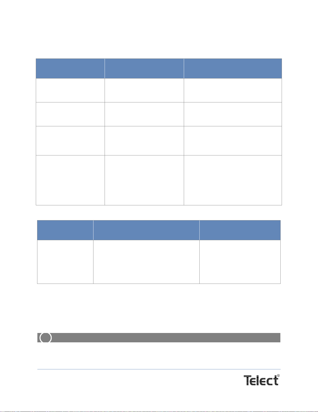
Table 2 - Fuse Alarm Reset Operation - Press button and release
Condition when
pressed Result of Press Meaning of result
Normal operating condition
No red LEDs, no remote
alarms activated
No change. No alarm conditions to reset.
GMT or KLM LED is red
(fuse alarm state) Fuse alarm LEDs turn OFF.
Alarm relays are cancelled,
return to normal state.
Fuse alarm LEDs change to reset mode
(OFF). Replacing fuse will turn LED
to GREEN.
Power A or Power B LED
is OFF. No change. Power alarm relay
is still on. Power A and Power B LEDs are turned
green (normal) only by restoring power.
Power alarm relays are only cleared by
restoring power.
Any condition All LEDs turn AMBER.
All remote alarm relays switch
toalarmcondition. (Notify alarm
center before test!)
This test condition clears whe
button is released - previous
status of all LEDs is restored.
This tests all LEDs and alarm relay cir-
cuits, including the Power A and Power
B LEDs and remote power alarm relays.
Release button to end test and restore
previous condition.
Table 3 - Test Alarm Card Function - Press button for five seconds and hold in
Condition when
pressed Result of Press Meaning of result
Any condition All LEDs turn AMBER.
All remote alarm relays switch to alarm con-
dition. (Notify alarm center before test!)
This test condition clears when button is
released - previous status of all LEDs is
restored.
This tests all LEDs and alarm
relay circuits, including the
Power A and Power B LEDs and
remote power alarm relays.
Release button to end test and
restore previous condition.
Page 11
Telect, Inc. • USA +1.509.926.6000 • Mexico +52.33.3836.37.52
www.telect.com • © 2010 Telect, Inc., All Rights Reserved, 117200-4 A0
1.7 Replacing the Alarm Card
ALERT
!
ALERT! The alarm card is sensitive to electrostatic discharge. Use standard ESD
mitigation procedures.
1. Use a No. 1 Phillips screwdriver to loosen the alarm card’s two captive screws.
2. Pull the alarm card straight out of the panel.
3. Align the replacement alarm card with the opening on the face of the panel.
4. Slide the alarm card straight into the opening, so that the card’s edges are positioned in the
PCB guides.
5. Push until the card’s connector is firmly seated. The alarm card’s front panel should sit
against the face of the distribution panel.
6. Use a No. 1 Phillips screwdriver to secure the card’s captive screws just beyond
finger-tightness.
7. If desired, test the alarm card according to the alarm testing procedures above. Telect alarm
cards are factory-tested. Replacement testing may not be advisable if it affects office
system service.
1.8 Replacing Fuses
WARNING
!
WARNING! Only install UL-listed or R/C Supplementary Protectors in the output fuse
holder positions.
CAUTION
!
CAUTION! Exercise standard ESD mitigation procedures when installing fuses.
Review the following points before installing or replacing fuses in the KLM-PDP:
• The panel’s input current is limited to 200 amps per side (Input A and Input B) or 400
Amps total.
• The panel’s total output current is 200 amps per side.
• KLM fuses are limited to 30-amps rating, 25-amps load; GMT fuses are limited to 15-amps
rating, 12.5-amps load.
• Identify the reason for the fuse opening and correct the problem before replacing the fuse.

Page 12
Telect, Inc. • USA +1.509.926.6000 • Mexico +52.33.3836.37.52
www.telect.com • © 2010 Telect, Inc., All Rights Reserved, 117200-4 A0
CAUTION
!
CAUTION! Perform this procedure when this equipment is powered! Failure to follow this
procedure may damage equipment or cause equipment service interruptions.
1. Notify the alarm center that you are replacing a fuse.
2. Press the KLM ALARM RESET button.
3. Remove and replace the fuses.
4. Re-install load to equipment.
5. Make sure that the fuses remain closed.
6. Record your activity in the equipment log.
1.9 Service
1.9.1 In-Warranty Service
For assistance with installation, component identification, or missing parts, call Telect: 1-800-
551-4567 or 1-509-926-6000. An application engineer will help you. Telect will repair or replace
defective products.
NOTE: Call a Customer Service Representative for a Return Material Authorization (RMA) before
returning any equipment.
1.9.2 Out-Of-Warranty Service
The procedure for out-of-warranty service is the same as for in-warranty service, except that
Telect charges a processing fee, and you must submit a purchase order along with a Return
Material Authorization (RMA) before returning equipment. Call a Telect customer service
representative at 1-800-551-4567 for help getting these forms.
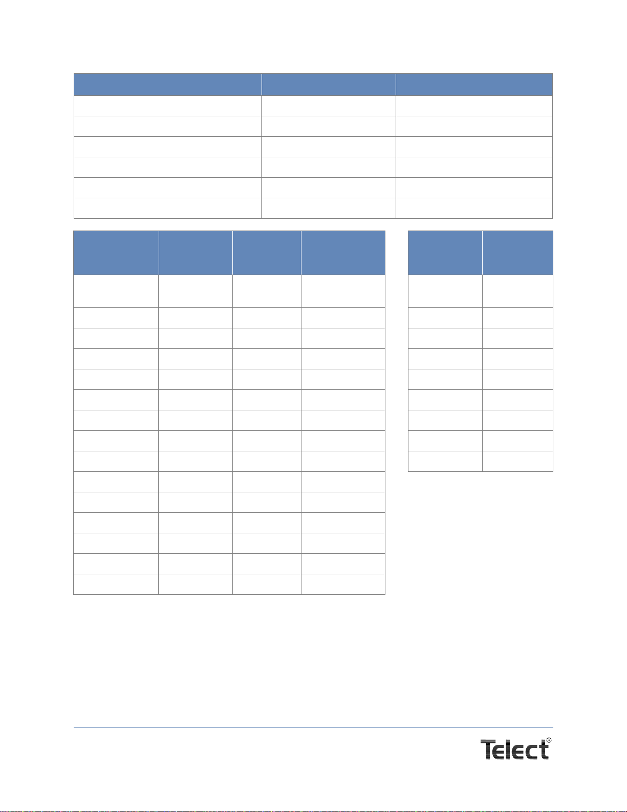
1.10 Accessories and Kits
Order on-line at telect.com, or contact your Telect customer service representative at 1-800-551-
4567 to order any of the accessories listed below.
Item Description Part Number
Replacement Alarm card Standard Telect 400315
Input terminal compression lugs for #2 AWG wire
for #4 AWG wire
for #6 AWG wire
T & B 256-30695-257
T & B 256-30695-1184
T & B 256-30695-253
Ground terminal compression lugs for #2 AWG wire
for #4 AWG wire
for #6 AWG wire
Telect 114552
Telect 110516
Telect 101686
Page 13
Telect, Inc. • USA +1.509.926.6000 • Mexico +52.33.3836.37.52
www.telect.com • © 2010 Telect, Inc., All Rights Reserved, 117200-4 A0
Output ring terminals single-hole Telect 104987
ETSI Mounting bracket black Telect 090-0041-0230
ETSI Mounting bracket white Telect 090-0041-0231
Phoney fuses - KLM Non-functional fuses Telect 110852
Phoney fuses - GMT Non-functional fuses Telect 132748
KLM/GMT Designation Label Removable Telect 117750-1
GMT Fuses Color Telect
Part
Number
Colored
Designation
Rivet
KLM
FUSE
AMPERA
Telect
Part
Number
Dummy fuse
(GMT) N/A 132748 N/A Dummy Fuse 110852
1/4A Violet 100151 102435-2 1 A 118675
1/2A Red 004001 102435-5 2 A 118676
3/4A Brown 004008 102435-7 5 A 118673
1A Gray 100991 102435-8 10A 118438
1 1/3A White 004006 102435-9 15 A 118439
1 1/2A White/yellow 004011 102435-10 20A 118440
2A Orange 004002 102435-11 25A 118441
3A Blue 004012 102435-13 30A 118442
4A White/brown 004013 102435-15
5A Green 004014 102435-16
7 1/2A Black/white 004010 102435-17
10A Red/white 004015 102435-18
12A Yellow/green 102287 102435-19
15A Red/blue 102288 102435-20
Item Description Part Number

Page 14
Telect, Inc. • USA +1.509.926.6000 • Mexico +52.33.3836.37.52
www.telect.com • © 2010 Telect, Inc., All Rights Reserved, 117200-4 A0
1.11 Reference Schematic
GMT
GMT
KLM 5
KLM 5
KLM 1
KLM 1
KLM 6
KLM 6
KLM 2
KLM 2
KLM 7
KLM 7
KLM 3
KLM 3
KLM 8
KLM 8
KLM 4
KLM 4
GMT
GMT
KLM ALARM 4
KLM ALARM 8
KLM ALARM 1
KLM ALARM 5
KLM ALARM 3
KLM ALARM 7
KLM ALARM 2
KLM ALARM 6
KLM ALARM 2
KLM ALARM 6
KLM ALARM 3
KLM ALARM 7
KLM ALARM 1
KLM ALARM 5
KLM ALARM 4
KLM ALARM 8
NO
NO
NC
NC
C
C
Note
Relays shown
in alarm state
/ -48V
/ -48V
5
6
7
8
5
6
7
8
5
6
7
8
5
6
7
8
Page 15
Telect, Inc. • USA +1.509.926.6000 • Mexico +52.33.3836.37.52
www.telect.com • © 2010 Telect, Inc., All Rights Reserved, 117200-4 A0
1.12 Physical Attributes
Telect assumes no liability from the application or use of these products. Neither does Telect
convey any license under its patent rights or the patent rights of others. This document and the
products described herein are subject to change without notice.
Rear View
Front View
8x8 KLM Power Distribution Panel - PN 009-8004-0208
3.47 in. (8.81 cm.)

Page 16
Telect, Inc. • USA +1.509.926.6000 • Mexico +52.33.3836.37.52
www.telect.com • © 2010 Telect, Inc., All Rights Reserved, 117200-4 A0
This page intentionally left blank.
Table of contents
Other Telect Control Panel manuals


Popular Control Panel manuals by other brands

Fike
Fike FIK-5496 Installation & operation manual

Vision
Vision OPLC V130-33-TA24 installation guide

Bosch
Bosch FPA-5000 Wiring guide

STG-BEIKIRCH
STG-BEIKIRCH TRZ Basic 4A Technical information and operating instruction

Intermatic
Intermatic PE45300 Installation, operation & service manual

Electronics Line
Electronics Line infiniti user manual


