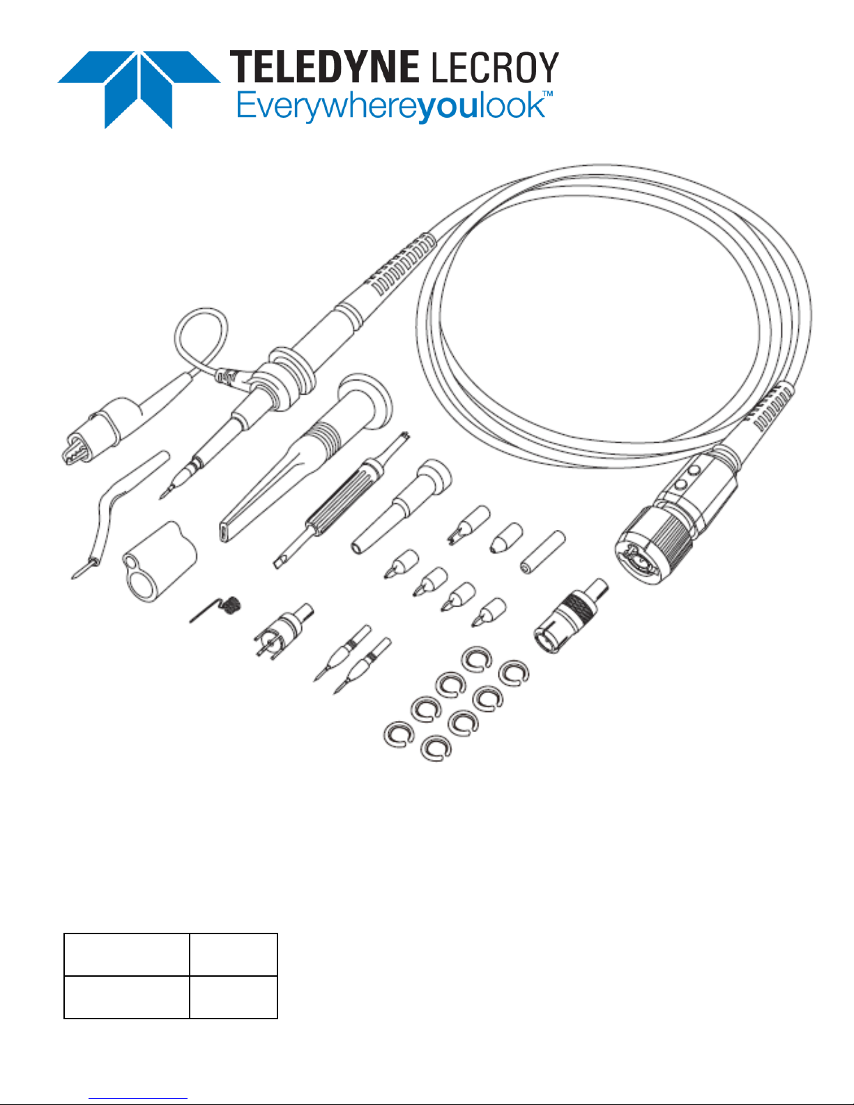
Teledyne Lecroy PP023 User manual

PP023-1
PP023-2
Operator’s Manual
PP02
3
Passive Probe

700 Chestnut Ridge Road
Chestnut Ridge, NY, 10977-6499
Tel: (845) 425-2000, Fax: (845) 578 5985
teledynelecroy.com
PP023 Passive Probe Instruction Manual
© 2015 Teledyne LeCroy, Inc. All rights reserved.
Unauthorized duplication of Teledyne LeCroy documentation materials other than for internal
sales and distribution purposes is strictly prohibited. However, clients are encouraged to
duplicate and distribute Teledyne LeCroy documentation for internal educational purposes.
Teledyne LeCroy is a registered trademark of Teledyne LeCroy, Inc. Other product or brand
names are trademarks or requested trademarks of their respective holders. Information in this
publication supersedes all earlier versions. Specifications subject to change without notice.
This electronic product is subject to disposal and recycling regulations
that vary by country and region. Many countries prohibit the disposal of
waste electronic equipment in standard waste receptacles. For more
information about proper disposal and recycling of your Teledyne LeCroy
product, visit teledynelecroy.com/recycle.
925646-00
May, 2015

Operator’s Manual
1
Terms and Symbols
The following symbols appear on the product or in its documentation:
DANGER
High Voltage
WARNING
Refer to Manual. Condition or practice
could result in injury or loss of life.
DOUBLE INSULATION
PROTECTIVE (EARTH) TERMINAL
Introduction
The Teledyne LeCroy PP023 is a passive high impedance voltage
oscilloscope probe designed and calibrated for use with general purpose
oscilloscopes having an input impedance of 1 MΩ and can be compensated
for use with instruments having an input capacitance between 10 to 20 pF.
It is compatible with oscilloscopes that automatically detect probe
attenuation and adjust their readout accordingly.

PP023 Passive Probe
2
Specifications
Model Attn.
Input
Imped.
B/W
Rise
Time
Length
Compensation
Range
R (MΩ) C (pF) (MHz) (ps) (m) (pF)
PP023
10x
10
10
500
700
1.3
10 - 20
Attenuation Ratio.....................10:1 ± 1%
Max. Input Voltage...................Measurement Category I 1: 500 Vrms
1500 V transient overvoltage
(see voltage derating curve on p. 3)
Measurement Category II 2: 400 Vrms
Pollution Degree ......................Pollution Degree 2 3
Operating Temperature ..........0° C to +50° C
Humidity ....................................5% to 95% RH (10° C to 30° C)
5% to 75% RH (30° C to 40° C)
5% to 50% RH (above 40° C)
RH not controlled below 10° C
Operating Altitude....................3000 meters maximum
To reduce risk of fire or electric shock, do not exceed the
voltage or category ratings of the probe.
Definitions (per EN 61010-031)
1) Measurement Category I (CAT I)refers to measurements performed on circuits not directly
connected to mains.
2) Measurement Category II (CAT II) refers to measurements performed on circuits directly
connected to the low-voltage installation.
3) Pollution Degree 2 refers to an operating environment where normally only dry, non-conductive
pollution occurs. Temporary conductivity caused by condensation must be expected.

Operator’s Manual
3
PP023 Input Impedance Profile
Voltage vs. Frequency Derating Curve

PP023 Passive Probe
4
EC Declaration of Conformity
The probe is marked with this symbol to show compliance was
demonstrated to the specifications listed in the Official Journal of
the European Communities: Low Voltage Directive 2006/95/EC:
EN 61010-031/A1:2008 Safety requirements for electrical equipment for
measurement, control and laboratory use – Part 031: Safety requirements
for handheld probe assemblies for electrical measurement and test.
EU RoHS Compliance
The probe and its accessories conform to the 2011/65/EU RoHS2 Directive,
as they have been classified as Industrial Monitoring and Control
Equipment (per Article 3, Paragraph 24) and are exempt from RoHS
compliance until 22 July 2017 (per Article 4, Paragraph 3).
General Safety Information
Observe generally accepted safety procedures in addition to those
listed here to avoid personal injury or damage to equipment. The
overall safety of any system incorporating this accessory is the
responsibility of the assembler of the system.
Connect only to grounded instruments. Use only with compatible Teledyne
LeCroy oscilloscopes that have their BNC input connected to an earth
ground. Do not connect the probe reference lead to any point which is at a
potential other than earth ground.
Connect and disconnect properly. Connect probe to the oscilloscope before
connecting it to the test circuit. Disconnect the probe input and reference
lead from the test circuit before disconnecting from the oscilloscope. Do
not connect or disconnect probes while they are connected to a voltage
source.

Operator’s Manual
5
Do not overload. Do not apply any potential to the probe leads that exceeds
the maximum rating of the probe. Always comply with the Voltage vs.
Frequency Derating Curve.
Observe all terminal ratings. Observe all markings on the oscilloscope
before connecting. Consult the oscilloscope product manual for further
ratings information.
Do not remove probe casing. Touching exposed connections may result in
electric shock.
Use indoors only within operational environment listed. Do not use in wet or
explosive atmospheres. Keep product surfaces clean and dry.
Handle with care. Probe tips are extremely sharp and may puncture skin or
cause other bodily injury if not handled properly.
Keep fingers behind the finger guard of probe body and accessories.
Do not operate with suspected failures. Before each use, inspect the probe
and accessories for any potential damage such as tears or other defects in
the probe body, cable jacket, accessories, etc. If any part is damaged, cease
operation immediately and sequester the probe from inadvertent use.
Cleaning
•Clean only the exterior of the probe, cables, and accessories. Use a
soft cotton cloth moistened with a mild detergent and water solution.
Do not allow any portion of the probe to be submerged at any time.
•Dry the probe and accessory thoroughly before attempting to make
any voltage measurement.
•Do not subject the probe to solvents or solvent fumes as these can
cause deterioration of the probe body, cables, and accessories.

PP023 Passive Probe
6
Probe Compensation
Proper compensation of the probe is required to assure amplitude accuracy
of the waveform being measured by matching the probe to the
oscilloscope’s input capacitance. Compensation should be adjusted
whenever the probe is connected to or transferred between oscilloscopes.
Low Frequency
1. Apply a 1 kHz square wave to the probe or connect to the
oscilloscope’s calibrator output.
2. Adjust the single LF trimmer located on the PP023 BNC Box until you
achieve a flat-topped square wave (see figure below):
High Frequency
1. Apply a 1 MHz square wave to the probe (< 0.7 ns rise-time).
2. Remove the plastic caps from the two, high-frequency trimmers on
the PP023 BNC Compensation Box.
3. Adjust HF2 then HF1 until you achieve a flat-topped square wave (see
figure below).

Operator’s Manual
7
Over-compensated, correct, and under-compensated waveforms
Probe Accessories
Probe Tips
Both the rigid probe tip and the spring tip can be screwed on to the probe
body by hand.
Be sure not to overtighten the tips to avoid damaging
the threads.
Ground Accessories
The ground lead and the short collar are attached to the probe at the time
of shipping. To replace the ground lead with the swivel lead adapter,
unscrew the short collar from the probe and remove the ground lead.
Replace the short collar to hold the swivel lead adapter in place.
Alternatively, the long collar can be pushed onto the probe body and used in
conjunction with the ground spring, BNC adapter or PCB adapter.
Service
Refer all service to qualified personnel.
For the most complete and up-to-date list of sales and service centers by
country, visit teledynelecroy.com/support/contact.

PP023 Passive Probe
8
Replaceable Parts
Item
Part Number
Description
QTY
1
PK5-2.5MM-101
Ground Lead with Alligator Clip
1
2
PK5-2.5MM-102
Rigid Probe Tip (1 installed standard)
2
3
PK5-2.5MM-103
Short Collar (installed standard)
1
4
PK5-2.5MM-104
Sprung Hook
1
5
PK5-PK6-001
Trimmer Tool
1
6
PK5-2.5MM-105
Long Collar
1
7
PK5-2.5MM-106
IC Tip Insulators (Black, Brown, Blue, Green, Gray)
5
8
PK5-2.5MM-107
Tip Insulator 2.5mm
1
9
PK5-2.5MM-108
Probe Tip Cover
1
10
PK5-2.5MM-109
BNC Adapter 2.5mm
1
11
PK5-2.5MM-110
Swivel Ground Lead
1
12
PK5-2.5MM-111
Swivel Ground Lead Adapter
1
13
PK5-2.5MM-112
Ground Spring
1
14
PK5-2.5MM-113
PCB Adapter
1
15
PK5-2.5MM-114
Spring Tip
1
16
PK5-PK6-002
Color Coding Rings (2 ea. yellow, red, green, blue)
8
Standard Accessory Replacement Kit part number is PKIT5-2.5MM-101.

Operator’s Manual
9
Warranty
NOTE: THE WARRANTY BELOW REPLACES ALL OTHER WARRANTIES,
EXPRESSED OR IMPLIED, INCLUDING BUT NOT LIMITED TO ANY IMPLIED
WARRANTY OF MERCHANTABILITY, FITNESS, OR ADEQUACY FOR ANY
PARTICULAR PURPOSE OR USE. TELEDYNE LECROY SHALL NOT BE LIABLE FOR
ANY SPECIAL, INCIDENTAL, OR CONSEQUENTIAL DAMAGES, WHETHER IN
CONTRACT OR OTHERWISE. THE CUSTOMER IS RESPONSIBLE FOR THE
TRANSPORTATION AND INSURANCE CHARGES FOR THE RETURN OF PRODUCTS
TO THE SERVICE FACILITY. TELEDYNE LECROY WILL RETURN ALL PRODUCTS
UNDER WARRANTY WITH TRANSPORT PREPAID.
Teledyne LeCroy warrants this oscilloscope accessory for normal use and
operation within specification for a period of one year from the date of shipment.
Spare parts, replacement parts and repairs are warranted for 90 days.
In exercising its warranty, Teledyne LeCroy, at its option, will either repair or replace
any assembly returned within the warranty period to the Customer Service
Department of an authorized service center. However, this will be done only if the
product is determined by Teledyne LeCroy’s examination to be defective because of
workmanship or materials, and the defect is not caused by misuse, neglect,
accident, abnormal conditions of operation; or, damaged by attempted repair or
modifications by a non-authorized service facility.
The customer will be responsible for the transportation and insurance charges for
the return of products to the service facility. Teledyne LeCroy will return all products
under warranty with transportation charges prepaid.
This warranty replaces all other warranties, expressed or implied, including, but not
limited to, any implied warranty of merchantability, fitness, or adequacy for any
particular purposes or use. Teledyne LeCroy shall not be liable for any special,
incidental, or consequential damages, whether in contract or otherwise.

925646-00
May, 2015
Other manuals for PP023
1
This manual suits for next models
2
Table of contents
Other Teledyne Lecroy Accessories manuals