Teledyne Lecroy CA10 User manual

Operator's
Manual
CA10
ProBus Current Adapter


CA10
ProBus Current Adapter
Operator's Manual
November, 2018

CA10 ProBus Current Adapter Operator's Manual
© 2018 Teledyne LeCroy, Inc. All rights reserved.
Unauthorized duplication of Teledyne LeCroy documentation materials other than for
internal sales and distribution purposes is strictly prohibited. However, clients are
encouraged to duplicate and distribute Teledyne LeCroy documentation for their own
internal educational purposes.
Teledyne LeCroy is a trademark of Teledyne LeCroy, Inc. Other product or brand
names are trademarks or requested trademarks of their respective holders.
Information in this publication supersedes all earlier versions. Specifications are
subject to change without notice.
925095 Rev B
November, 2018

Operator's Manual
Contents
Safety ii
Introduction 1
Standard Parts 1
Compatibility 1
Connecting the CA10 2
Using the Heat-Shrink Tubing 2
Connecting the CA10 to the Transducer/Transformer 2
Programming the CA10 4
Customizing the CA10 5
Resistive Termination 5
Filter Components 6
Opening the CA10 Case 8
Cleaning 8
Returning a Product for Service 9
Contact Teledyne LeCroy 9
Certifications 10
EMC Compliance 10
Safety Compliance 11
Environmental Compliance 11
i

CA10 ProBus Current Adapter
Safety
Observe these instructions to keep the product operating in a correct and safe
condition. Follow generally accepted safety procedures in addition to the precautions
specified in this section. The overall safety of any system incorporating this product
is the responsibility of the assembler of the system.
Symbols
These symbols appear on the product or in its documentation to alert you to
important safety considerations.
CAUTION of potential damage to product, or WARNING of potential bodily
injury. Refer to the manual to protect against injury or damage. Do not
proceed until conditions are fully understood and met.
Precautions
Use only as intended. The product is intended to be used only with the compatible
Teledyne LeCroy instruments. Using the product and/or the equipment it is connected
to in a manner other than specified may impair the protection mechanisms.
Do not apply a voltage to any input that exceeds the maximum rating of that input.
Refer to the body of the oscilloscope and the product page at teledynelecroy.com for
detailed information.
Use indoors only. The accessory is intended for indoor use and should be operated in
a clean, dry, environment. Do not use in wet/damp or explosive atmospheres.
Keep product surfaces clean and dry. See "Cleaning" for instructions.
Do not operate with suspected failures. Do not use the product if any part is damaged.
Refer all maintenance to qualified service personnel.
ii

Operator's Manual
Introduction
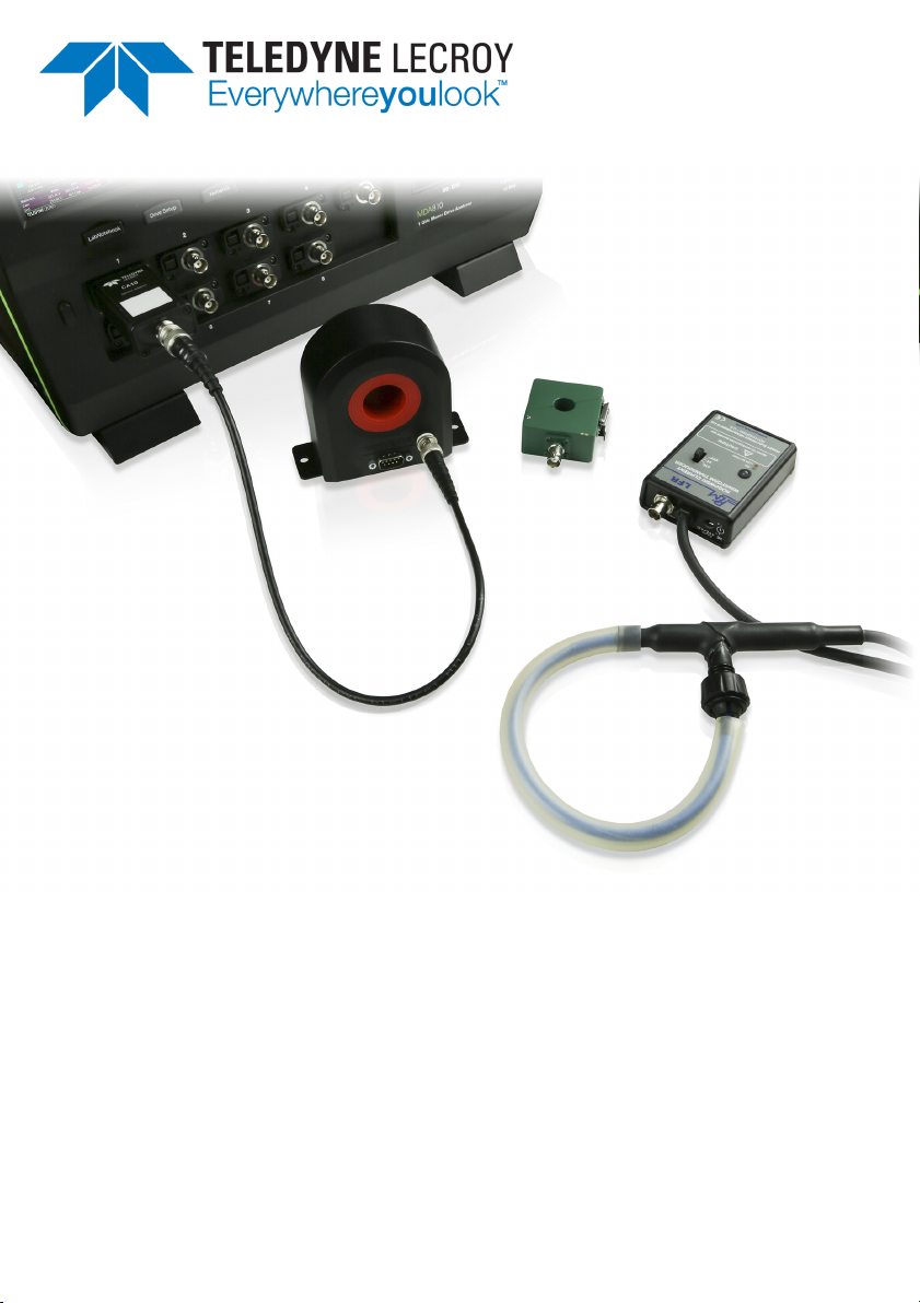
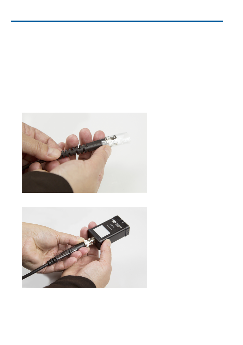
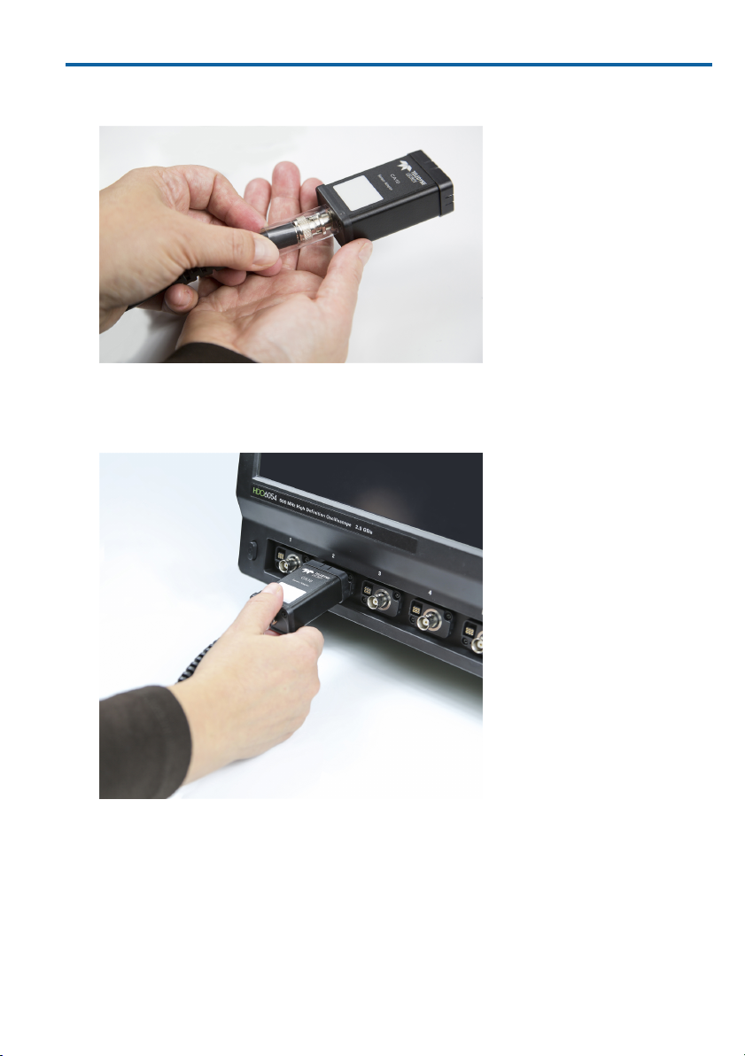
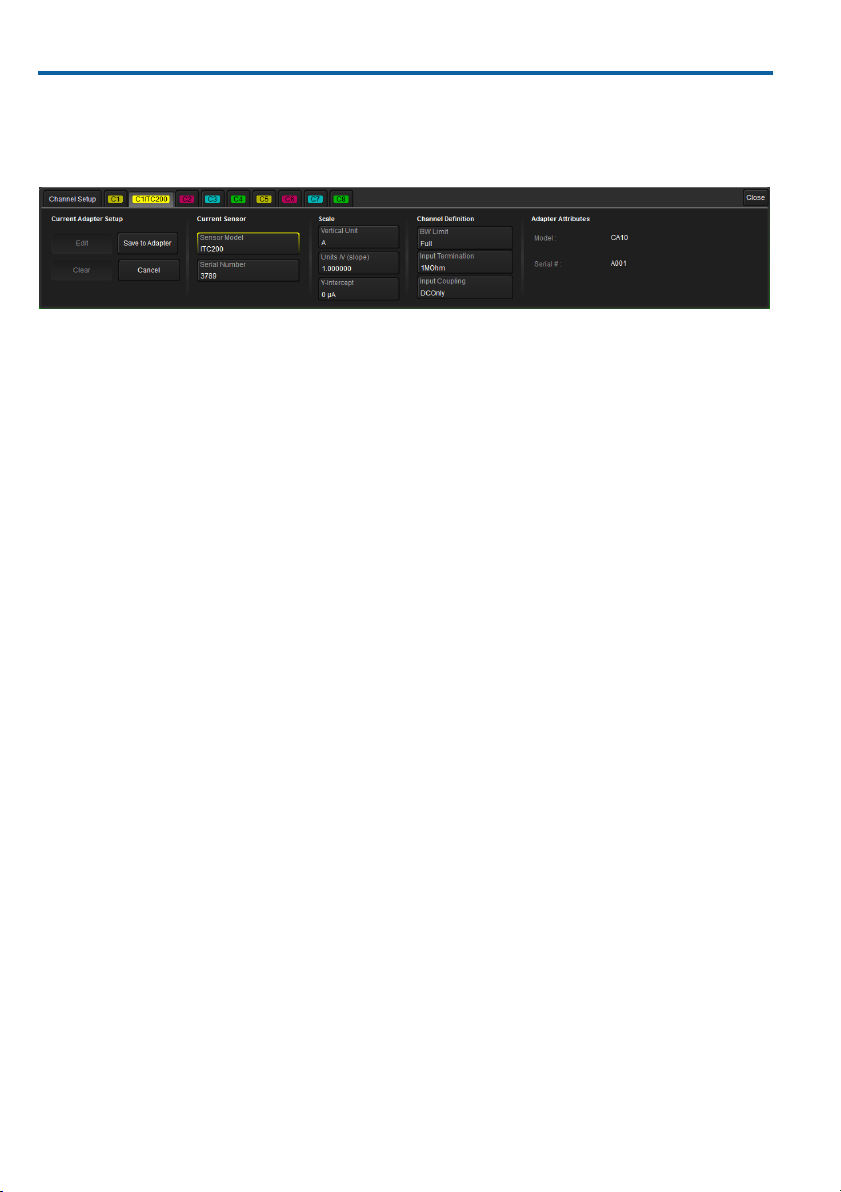
The CA10 ProBus Current Adapter allows current transducers and transformers that
output a voltage or current signal proportional to a measured current to be easily
connected to an oscilloscope or motor drive analyzer. Specific information about the
input device is programmed into the CA10 so that when the device is connected to
the instrument it will correct for the transducer/transformer gain or attenuation and
display the result in Ampere units.
Using the CA10 with transducers/transformers saves the time (and errors) involved
in manually entering scaling factors and units each time the device is connected to
the instrument.
CAUTION. The secondary of a current transformer (CT), when unterminated,
can generate hazardous open-circuit voltages when energized. These
voltages could be dangerous to personnel and damage the oscilloscope. If the
CA10 is used with an unterminated current transformer, you must install a
suitably rated terminating resistor in the CA10 before energizing the CT. See
Customizing the CA10 for details.
Standard Parts
These parts are delivered with the CA10. Contact us immediately if parts are
missing.
Part P/N Delivered QTY
CA10 924491-00 1
Heat-shrink tubing (6" length) 42A0000006098 1
Removable labels (sheet of 20) 42A0000006132 1
Quick Start Guide 925590-00 1
Compatibility
The CA10 current adapter is compatible with any Teledyne LeCroy HDO, MDA,
WaveRunner, WavePro or WaveMaster Series oscilloscope that is equipped with the
ProBus or ProBus2 interface and 64-bit XStreamDSO software version 7.8.x.x or
greater.
1

CA10 ProBus Current Adapter
Connecting the CA10
Using the Heat-Shrink Tubing
We highly recommend using the included heat-shrink tubing to semi-permanently
attach the CA10 to the transducer/transformer for which it has been programmed.
However, the heat-shrink tubing is not required, and the CA10 will function perfectly
without it.
Cut the tubing into 1.5" length sleeves before using.
Connecting the CA10 to the Transducer/Transformer
1. Slip one of the sleeves over the transducer/transformer's BNC output connector.
2. Connect the device to the CA10 BNC input connector.
2

Operator's Manual
3. Slide up the sleeve so that it is flush to the body of the CA10 and completely
covers the connector. Apply heat until the wrap snugly encases the connection.
4. If desired, attach a removable label the front of the CA10 case and write the
name and/or setup of the attached device.
5. Connect the CA10 to a ProBus input on the instrument.
3

CA10 ProBus Current Adapter
Programming the CA10
When the CA10 is first connected to the instrument, you will be asked if you want to
program it. Select Yes to display the CA10 dialog:
Enter all the device settings on the dialog, then select Save to Adapter.
In the future, the CA10 will update channel settings automatically as long as there is a
program saved on it. The CA10 dialog will appear behind the input channel dialog
whenever it is connected to the instrument, with the sensor name appearing next to
the channel number on the tab.
To change the programming, open the CA10 dialog, then select Edit before modifying
the settings. Use Clear to quickly clear the previous settings. These buttons are only
active after a program has been saved.
Remember to Save to Adapter after reprogramming.
4

Operator's Manual
Customizing the CA10
Current transducers with a voltage output proportional to a current input can directly
drive the input impedance of the instrument: DC1MΩ, AC1MΩ or 50Ω.
Bandwidth filters can be applied to the input chanels via the CA10 programming
interface: Full BW, 200MHz or 20MHz.
It is also possible to customize the CA10 through addition of shunt resistors and
other bandwidth filtering components. Current transformers (CTs) output a current
signal proportional to the turns ratio and require that a suitably rated R4, R13 and/or
R14 terminating resistor be installed in the CA10 to provide a voltage output to the
oscilloscope. It is the operator's responsibility to ensure that these resistors are
suitably rated for the input current at J3 in the schematic below.
A schematic of the user-installable components is shown below. The CA10 comes
from the factory with a 0Ω (short) installed in the L1 location, and no components in
the other locations shown.
Resistive Termination
The locations R13 and R14 can be used to install a specific value of termination
resistance. These two locations will allow 1206 sized surface mount resistors to be
installed. The location R4 is intended for a precision axial resistor and is particularly
suited to small value precision resistors that might be required.
5

CA10 ProBus Current Adapter
Filter Components
The locations C7, C8 and L1 can be used to create a filter to remove higher frequency
noise that might be present at a current transducer or transformer output. The
specific components that might be installed depends on the desired frequency
response as well as the instrument and transducer impedance. Some possible
combinations are shown below:
Scope termination 1MΩ
Source termination 50Ω
-3dB FREQUENCY 1 MHz
L1 50Ω
C7 3nF
Scope termination 1MΩ
Source termination 50Ω
-3dB FREQUENCY 10MHz
L1 50Ω
C7 300pF
Scope termination 50Ω
Source termination 50Ω
-3dB FREQUENCY 1MHz
C7 3300pF
L1 15uH
C8 3300pF
Scope termination 50Ω
Source termination 50Ω
-3dB FREQUENCY 10MHz
C7 330pF
L1 1.5uH
C8 330pF
6

Operator's Manual
7

CA10 ProBus Current Adapter
Opening the CA10 Case
To open the CA10 case:
1. Remove the two screws on the connector end of the adapter (shown at bottom of
the image below).
2. Remove the front face and pull out the PCA board.
3. After modifying the signal path components, replace all parts in the order shown.
NOTE: The screws on the front case are installed with 2 in-lbs. torque.
Cleaning
Clean only the exterior of the product using a soft cloth moistened with water or an
alcohol solution. Do not use harsh chemicals or abrasive elements. Under no
circumstances submerge the device or allow moisture to penetrate it.
8

Operator's Manual
Returning a Product for Service
Contact your regional Teledyne LeCroy service center for calibration or other
service. If the product cannot be serviced on location, the service center will give you
aReturn Material Authorization (RMA) code and instruct you where to ship the
product. All products returned to the factory must have an RMA.
Return shipments must be prepaid. Teledyne LeCroy cannot accept COD or Collect
shipments. We recommend air-freighting. Insure the item you’re returning for at
least the replacement cost.
1. Remove all accessories from the device.
2. Pack the product in its case, surrounded by the original packing material (or
equivalent). Do not include the manual.
3. Label the case with a tag containing:
lThe RMA
lName and address of the owner
lProduct model and serial number
lDescription of failure or requisite service
4. Pack the product case in a cardboard shipping box with adequate padding to
avoid damage in transit.
5. Mark the outside of the box with the shipping address given to you by Teledyne
LeCroy; be sure to add the following:
lATTN: <RMA code assigned by Teledyne LeCroy>
lFRAGILE
6. If returning a product to a different country:
lMark the shipment as a "Return of US manufactured goods for warranty
repair/recalibration."
lIf there is a cost for the service, list the cost in the Value column and the
original purchase price "For insurance purposes only."
lBe very specific about the reason for shipment. Duties may have to be paid
on the value of the service.
Extended warranty, calibration, and upgrade plans are available for purchase.
Contact your Teledyne LeCroy sales representative.
Contact Teledyne LeCroy
For the most complete and up-to-date list of sales and customer care centers by
country, visit: teledynelecroy.com/support/contact
9

CA10 ProBus Current Adapter
Certifications
EMC Compliance
EC Declaration of Conformity - EMC
The product meets the intent of EC Directive 2004/108/EC for Electromagnetic
Compatibility. Compliance was demonstrated to the following specifications as listed
in the Official Journal of the European Communities:
EN 61326-1:2013, EMC requirements for electrical equipment for measurement,
control, and laboratory use.1, 2, 3
1 This product is intended for use in nonresidential areas only. Use in residential areas may cause
electromagnetic interference.
2 Emissions exceeding the levels required by this standard may occur when product is connected to a test
object.
3 To ensure compliance with the applicable EMC standards, use high quality shielded interface cables.
European Contact:*
Teledyne LeCroy Europe GmbH
Im Breitspiel 11c
D-69126 Heidelberg
Germany
Tel: + 49 6221 82700
Australia & New Zealand Declaration of Conformity - EMC
The product complies with the EMC provision of the Radio Communications Act per
the following standards, in accordance with requirements imposed by Australian
Communication and Media Authority (ACMA):
AS/NZS CISPR 11:2011 Radiated and Conducted Emissions, Group 1,
Class A.
Australia / New Zealand Contacts:*
RS Components Pty Ltd.
Suite 326 The Parade West
Kent Town, South Australia 5067
RS Components Ltd.
Unit 30 & 31 Warehouse World
761 Great South Road
Penrose, Auckland, New Zealand
* Visit teledynelecroy.com/support/contact for the latest contact information.
10

Operator's Manual
Safety Compliance
EC Declaration of Conformity - Low Voltage
The product meets the intent of EC Directive 2006/95/EC for Product Safety.
Compliance was demonstrated to the following specifications as listed in the Official
Journal of the European Communities:
IEC/EN 61010-031:2015 Safety requirements for electrical equipment for
measurement, control, and laboratory use – Part 031: Safety requirements for hand-
held probe assemblies for electrical measurement and test.
Environmental Compliance
End-of-Life Handling
The product is marked with this symbol to indicate that it complies with
the applicable European Union requirements to Directives 2002/96/EC
and 2006/66/EC on Waste Electrical and Electronic Equipment (WEEE)
and Batteries.
The product is subject to disposal and recycling regulations that vary by
country and region. Many countries prohibit the disposal of waste electronic
equipment in standard waste receptacles. For more information about proper
disposal and recycling of your Teledyne LeCroy product, please visit
teledynelecroy.com/recycle.
Restriction of Hazardous Substances (RoHS)
The product and its accessories conform to the 2011/65/EU RoHS2 Directive, as
they have been classified as Industrial Monitoring and Control Equipment (per Article
3, Paragraph 24) and are exempt from RoHS compliance until 22 July 2017 (per
Article 4, Paragraph 3).
11

CA10 ProBus Current Adapter
Warranty
THE WARRANTY BELOW REPLACES ALL OTHER WARRANTIES, EXPRESSED OR IMPLIED,
INCLUDING BUT NOT LIMITED TO ANY IMPLIED WARRANTY OF MERCHANTABILITY,
FITNESS, OR ADEQUACY FOR ANY PARTICULAR PURPOSE OR USE. TELEDYNE LECROY
SHALL NOT BE LIABLE FOR ANY SPECIAL, INCIDENTAL, OR CONSEQUENTIAL DAMAGES,
WHETHER IN CONTRACT OR OTHERWISE. THE CUSTOMER IS RESPONSIBLE FOR THE
TRANSPORTATION AND INSURANCE CHARGES FOR THE RETURN OF PRODUCTS TO THE
SERVICE FACILITY. TELEDYNE LECROY WILL RETURN ALL PRODUCTS UNDER WARRANTY
WITH TRANSPORT PREPAID.
The product is warranted for normal use and operation, within specifications, for a
period of one year from shipment. Teledyne LeCroy will either repair or, at our option,
replace any product returned to one of our authorized service centers within this
period. However, in order to do this we must first examine the product and find that it
is defective due to workmanship or materials and not due to misuse, neglect,
accident, or abnormal conditions or operation.
Teledyne LeCroy shall not be responsible for any defect, damage, or failure caused by
any of the following: a) attempted repairs or installations by personnel other than
Teledyne LeCroy representatives, b) improper connection to incompatible equipment,
or c) use of non-Teledyne LeCroy supplies. Furthermore, Teledyne LeCroy shall not
be obligated to service a product that has been modified or integrated where the
modification or integration increases the task duration or difficulty of servicing the
product. Spare and replacement parts and repairs all have a 90-day warranty.
Products not made by Teledyne LeCroy are covered solely by the warranty of the
original equipment manufacturer.
12


925095 Rev B
November, 2018
Table of contents
Other Teledyne Lecroy Adapter manuals