Teledyne RD Instruments SENTINEL V SELF-CONTAINED User manual

Information included herein is controlled by the Export Administration Regulations (EAR) and may
require an export license, license exception or other approval from the appropriate U.S. Government
agency before being exported from the United States or provided to any foreign person. Diversion
contrary to U.S. law is prohibited.
SENTINEL VSELF-CONTAINED
SENTINEL VREAL-TIME
OPERATION MANUAL
P/N 95D-6002-00 (September 2017)
© 2017 Teledyne RD Instruments, Inc. All rights reserved.

Page ii
EAR-Controlled Technology Subject to Restrictions Contained on the Cover Page.

Page iii
EAR-Controlled Technology Subject to Restrictions Contained on the Cover Page.
TABLE OF CONTENTS
CHAPTER 1–SELF-CONTAINED SENTINEL VOVERVIEW ...............................................................................................1
Sentinel V Features ......................................................................................................................................2
Available Options .........................................................................................................................................5
System Inventory .........................................................................................................................................6
Software Overview.......................................................................................................................................6
Computer Considerations ............................................................................................................................7
Power Considerations ..................................................................................................................................8
Touch Sensor Response / System Beeps ......................................................................................................9
Connecting to the Sentinel V ADCP..............................................................................................................9
Using the Wireless Connection ............................................................................................................10
Touch Sensor .................................................................................................................................11
Connect..........................................................................................................................................11
Start ReadyV ..................................................................................................................................12
Connecting to another ADCP................................................................................................................14
Restoring a ReadyV Lost Connection....................................................................................................15
Wireless Connection Common Issues ..................................................................................................16
CHAPTER 1A –REAL-TIME SENTINEL VOVERVIEW .....................................................................................................21
Sentinel V Real-Time Features .....................................................................................................................22
Available Real-Time Options ................................................................................................................23
Health & Environment Monitoring Sensors .........................................................................................24
Comparing Self-Contained & Real-Time...............................................................................................25
Real-Time System Inventory ........................................................................................................................26
Real-Time Software Overview......................................................................................................................27
Real-Time Computer Considerations ...........................................................................................................28
Real-Time Power Considerations .................................................................................................................29
Real-Time Touch Sensor Response / System Beeps .....................................................................................30
Real-Time ADCP Commands ........................................................................................................................30
Connecting to the Sentinel V Real-Time.......................................................................................................31
Using Sentinel V RT Utilities .................................................................................................................32
Using Ethernet Communications..........................................................................................................33
Using Directed UDP Output ...........................................................................................................33
Using UDP broadcast Output .........................................................................................................34
Using the Sentinel-V Real-Time Utilities Page ......................................................................................34
Installing Sentinel-V Real-Time Firmware Upgrades......................................................................34
Downloading Sentinel V Real-Time Log Files .................................................................................36
Installing Feature Upgrades .........................................................................................................................37
Using the Trigger ..........................................................................................................................................38
CHAPTER 1C –SWITCHING RT AND SC MODES .........................................................................................................39
Switching RT and SC Modes .........................................................................................................................39
Switching to the Sentinel V Real-Time Mode.......................................................................................40
Switching to the Sentinel V Self-Contained Mode ...............................................................................41
CHAPTER 2–USING READYV ...............................................................................................................................43
ReadyV Interface Features ...........................................................................................................................44
Using the Home Panel..................................................................................................................................46
Using the ReadyV Panels ......................................................................................................................47
Creating and Saving Scenarios..............................................................................................................48
Collecting Waves Data..........................................................................................................................50
Example Waves Setups ..................................................................................................................51
Opening a Saved Scenario ....................................................................................................................51
Deleting a Saved Scenario ....................................................................................................................52
Using the Set Sampling Strategy Panels .......................................................................................................53

Page iv
EAR-Controlled Technology Subject to Restrictions Contained on the Cover Page.
Error Messages.....................................................................................................................................54
Step 1: Scenario....................................................................................................................................54
Step 2: Settings.....................................................................................................................................55
Using Real-Time Serial Data Output.............................................................................................................55
Serial Port Application Notes ...............................................................................................................57
Step 3: Profiling ....................................................................................................................................59
Using the Review System Panel ...................................................................................................................61
Sensor Data ..........................................................................................................................................62
Activating and Deactivating Features...................................................................................................64
Using the Download Data Panel...................................................................................................................65
Using Download Managers ..................................................................................................................67
Using the System Check Panel .....................................................................................................................68
Installing Firmware Upgrades ..............................................................................................................69
ReadyV Log Files...................................................................................................................................70
Using the Review Resources Panel...............................................................................................................70
Using the Deployment Checklist Panel ........................................................................................................72
Starting or Stopping Deployments .......................................................................................................73
Running ReadyV Offline ...............................................................................................................................74
CHAPTER 3-INSTALLATION ..................................................................................................................................75
Attaching the Handle ...................................................................................................................................76
Transducer Cover .........................................................................................................................................76
Mounting the Instrument ............................................................................................................................77
WorkHorse to Sentinel V Mount Adapter ....................................................................................................79
Connecting Cables and Dummy Plugs ..........................................................................................................80
Using the AC Power Adapter........................................................................................................................81
Cable Wiring Diagrams.................................................................................................................................82
Connecting the External Battery Case..........................................................................................................83
Using Bottom Mounts ..................................................................................................................................84
Using Buoy Mounts and Load Cages ............................................................................................................86
Using an Over-the-Side Mount.....................................................................................................................87
Over-the-Side Mounting Special Considerations .................................................................................87
Routing Cables .............................................................................................................................................88
Using a Sea Chest .........................................................................................................................................90
CHAPTER 4-MAINTENANCE.................................................................................................................................93
Maintenance Schedule.................................................................................................................................94
Calibration Items ..................................................................................................................................94
Maintenance Items and Inspection......................................................................................................95
Parts Location Drawings...............................................................................................................................96
Tools and Spares Parts .................................................................................................................................97
Disassembly and Assembly Procedures .......................................................................................................102
Disassembling the Sentinel V ...............................................................................................................102
Removing the End-Cap...................................................................................................................102
Removing the Transducer Head Assembly.....................................................................................103
Reassembling the Sentinel V ................................................................................................................104
Replacing the End-Cap ...................................................................................................................104
Replacing the Transducer Head Assembly .....................................................................................106
Replacing the Sentinel V Battery..................................................................................................................107
Testing the Lithium Battery Pack..........................................................................................................107
Replacing the Battery Pack...................................................................................................................108
Replacing Individual D Cell Batteries....................................................................................................109
Replacing the External Battery Case Packs...........................................................................................111
Calibrating the Compass ..............................................................................................................................112
Compass Calibration.............................................................................................................................114
Using the Compass Calibration Stand ..................................................................................................116
Calibration Score ..................................................................................................................................118
Troubleshooting a Low Calibration Score.............................................................................................119

Page v
EAR-Controlled Technology Subject to Restrictions Contained on the Cover Page.
Restore to Factory Defaults..................................................................................................................119
Periodic Maintenance ..................................................................................................................................120
Running the Built-in Tests ....................................................................................................................121
Testing the Sentinel V Self-Contained............................................................................................121
Testing the Sentinel V Real-Time ...................................................................................................121
Setting the Date and Time....................................................................................................................122
Setting the Date and Time on Self-Contained Systems..................................................................122
Setting the Date and Time on Real-Time Systems .........................................................................123
Replacing the O-Ring ............................................................................................................................124
Filling the Pressure Sensor Cavity with Oil ...........................................................................................125
Zero the Pressure Sensor .....................................................................................................................127
Cleaning the Thermistor Cover.............................................................................................................127
Replacing the Desiccant .......................................................................................................................128
Replacing the Captive Nuts ..................................................................................................................129
Replacing the Battery Springs ..............................................................................................................130
Replacing the Battery Separators.........................................................................................................130
Preventing Biofouling ...........................................................................................................................131
Removing Biofouling ............................................................................................................................132
CHAPTER 5-TROUBLESHOOTING ...........................................................................................................................133
Troubleshooting Steps .................................................................................................................................134
Troubleshooting Communication Issues ......................................................................................................134
Determining if the System is RT or SC ..........................................................................................................135
Troubleshooting Wireless Issues..................................................................................................................135
Troubleshooting Serial Issues.......................................................................................................................136
Troubleshooting Ethernet Issues .................................................................................................................137
Troubleshooting UDP Issues.................................................................................................................137
Troubleshooting ReadyV Issues ...................................................................................................................138
ReadyV Does Not Start .........................................................................................................................138
Solving Partially Cut Off Screen Issues .................................................................................................138
Solving Download Data Issues..............................................................................................................138
Troubleshooting a Built-In Test Failure ........................................................................................................140
Troubleshooting Data Problems ..................................................................................................................140
Using Board-Level Ethernet Connection ......................................................................................................141
Open the Transducer............................................................................................................................141
Connecting to the ADCP via Ethernet...................................................................................................141
Replacing the Transducer Head Assembly ...........................................................................................143
Troubleshooting a System Reset Issue.........................................................................................................143
CHAPTER 6-RETURNING SYSTEMS TO TRDI FOR SERVICE ............................................................................................145
Shipping the ADCP .......................................................................................................................................146
Returning Systems to the TRDI.....................................................................................................................147
Returning Systems to TRDI Europe ..............................................................................................................148
CHAPTER 7-SPECIFICATIONS ................................................................................................................................151
Outline Installation Drawings.......................................................................................................................157
CHAPTER 8–REAL-TIME COMMANDS ....................................................................................................................183
Data Communication and Command Format ..............................................................................................184
Command Input Processing .................................................................................................................184
Data Output Processing........................................................................................................................185
Command Summary.....................................................................................................................................186
Command Descriptions ................................................................................................................................189
? – Help Menus ..............................................................................................................................189
Break..............................................................................................................................................190
OL – Display Feature List ................................................................................................................190
Y – Display Banner .........................................................................................................................191
Sensor Commands .......................................................................................................................................192
Available Sensor Commands ................................................................................................................192

Page vi
EAR-Controlled Technology Subject to Restrictions Contained on the Cover Page.
Standard Sensor Commands ................................................................................................................192
AZ – Zero Pressure Sensor .............................................................................................................192
Bottom Track Commands.............................................................................................................................193
Available Bottom Track Commands .....................................................................................................193
BA - Evaluation Amplitude Minimum.............................................................................................194
BC - Correlation Magnitude Minimum...........................................................................................194
BE - Error Velocity Maximum .........................................................................................................194
BF - Manual Fixed Altitude.............................................................................................................195
BP – Bottom-Track Pings per Ensemble .........................................................................................195
BX – Maximum Search Altitude .....................................................................................................196
Expert Bottom Track Commands .........................................................................................................197
#BB – Bottom Blank .......................................................................................................................197
#BH – Gain Switch Threshold .........................................................................................................197
#BI – Gain Switch Altitude..............................................................................................................197
#BY – Transmit Length ...................................................................................................................198
Control System Commands..........................................................................................................................199
Available Control System Commands ..................................................................................................199
Control System Command Descriptions...............................................................................................199
CB – Serial Port Control..................................................................................................................199
CF – Set Control Flags.....................................................................................................................200
CK – Save Command Parameters to Flash .....................................................................................201
CN - Network Configuration Menu ................................................................................................201
CR – Restore Command Defaults ...................................................................................................203
CS – Start Pinging (Go) ...................................................................................................................204
CState – Pinging State Query .........................................................................................................204
CStop – Stop Pinging ......................................................................................................................204
CT – Turnkey Mode ........................................................................................................................205
CU - Set Update Mode ...................................................................................................................206
CW – Output the Last Stored Ensemble.........................................................................................207
Expert Control System Commands.......................................................................................................208
#CC – Update Global Variables ......................................................................................................208
#CG – Set Beam Matrix Output Frequency ....................................................................................208
#CR – Reboot System .....................................................................................................................208
#CM – Set System Communication Mode .....................................................................................209
Environmental Commands...........................................................................................................................210
Available Environmental Commands ...................................................................................................210
Environmental Command Descriptions................................................................................................210
EA – Heading Alignment ................................................................................................................210
EB – Heading Bias...........................................................................................................................211
EC – Speed of Sound ......................................................................................................................211
ED – Depth of Transducer ..............................................................................................................212
EH – Heading..................................................................................................................................212
EM – Disable Beam ........................................................................................................................213
EP – Pitch (Tilt 1) ............................................................................................................................213
ER – Roll (Tilt 2) ..............................................................................................................................213
ES – Salinity ....................................................................................................................................214
ET – Temperature ..........................................................................................................................214
EU – System Orientation ................................................................................................................214
EX – Coordinate Transformation....................................................................................................215
EZ – Sensor Source.........................................................................................................................218
Expert Environmental Command Descriptions ....................................................................................219
#EI - Roll Misalignment Angle ........................................................................................................219
#EJ - Pitch Misalignment Angle ......................................................................................................220
Fault Log Commands....................................................................................................................................221
Available Fault Log Commands ............................................................................................................221
Fault Log Command Descriptions.........................................................................................................221
FC – Clear Fault Log........................................................................................................................221

Page vii
EAR-Controlled Technology Subject to Restrictions Contained on the Cover Page.
FD – Display Fault Log ....................................................................................................................221
Performance and Testing Commands ..........................................................................................................222
Available Performance and Testing Commands...................................................................................222
Performance and Testing Command Descriptions ...............................................................................222
PA – Run Go/No-Go Tests ..............................................................................................................222
PC – User Interactive Built-In Tests ................................................................................................223
PD – Set Output Format.................................................................................................................225
PF – Results from most recent PA tests .........................................................................................225
PS – Display System Parameters ....................................................................................................225
PT – Built-In Tests...........................................................................................................................227
Sync/Trigger Commands ..............................................................................................................................228
Available Sync/Trigger Commands.......................................................................................................228
SA – Trigger Events ........................................................................................................................228
SM – Trigger Mode ........................................................................................................................228
ST – Trigger Timeout ......................................................................................................................229
Timing Commands .......................................................................................................................................230
Available Timing Commands ................................................................................................................230
Standard Timing Commands ................................................................................................................230
TE – Time Per Ensemble.................................................................................................................230
TP – Time Between Pings ...............................................................................................................231
TS – Set Real-Time Clock ................................................................................................................231
Expert Timing Commands ....................................................................................................................232
#TM – Set Minimum Time Between Pings .....................................................................................232
Water Profiling Commands ..........................................................................................................................233
Available Water Profiling Commands...................................................................................................233
Standard Water Profiling Commands...................................................................................................234
WB – Bandwidth ............................................................................................................................234
WC – Correlation Threshold...........................................................................................................234
WD – Data Out ...............................................................................................................................235
WF – Blank after Transmit .............................................................................................................235
WM – Water Profiling Mode..........................................................................................................236
WN – Number of Bins ....................................................................................................................236
WP – Number of Pings ...................................................................................................................236
WS – Bin Size..................................................................................................................................237
WV – Ambiguity Velocity ...............................................................................................................237
Expert Water Profiling Commands.......................................................................................................238
#WA – False Target Threshold .......................................................................................................238
#WE - Error Velocity Threshold......................................................................................................238
#WJ – BroadBand Receiver Gain ....................................................................................................239
#WT – Transmit Length ..................................................................................................................239
Vertical Beam Profile Commands.................................................................................................................240
Available Vertical Beam Profile Commands .........................................................................................240
Standard Vertical Beam Profile Commands .........................................................................................240
ZP – Vertical Beam Number of Pings..............................................................................................240
Expert Vertical Beam Profile Commands .............................................................................................241
#ZB – Vertical Beam Bandwidth.....................................................................................................241
#ZC – Vertical Beam Correlation Threshold ...................................................................................241
#ZD – Vertical Beam Data Out .......................................................................................................241
#ZF – Vertical Beam Blanking Distance ..........................................................................................242
#ZJ – Vertical Beam Gain................................................................................................................242
#ZM – Vertical Beam Profile Mode ................................................................................................243
#ZN – Vertical Beam Number of Bins.............................................................................................243
#ZS – Vertical Beam Bin Size ..........................................................................................................244
#ZV – Vertical Beam Ambiguity Velocity........................................................................................244
CHAPTER 9–OUTPUT DATA FORMAT.....................................................................................................................245
Comparing Sentinel V PD0 to WorkHorse PD0.............................................................................................246
PD0 Output Data Format .............................................................................................................................248

Page viii
EAR-Controlled Technology Subject to Restrictions Contained on the Cover Page.
Header Data Format.............................................................................................................................249
Fixed Leader Data Format ....................................................................................................................251
Variable Leader Data Format ...............................................................................................................256
Velocity Data Format............................................................................................................................261
Correlation Magnitude, Echo Intensity, and Percent-Good Data Format ............................................263
Transformation Matrix Format ............................................................................................................266
Sentinel V Specific Structures...............................................................................................................268
Sentinel V System Configuration....................................................................................................268
Sentinel V Ping Setup .....................................................................................................................270
Sentinel V ADC Data.......................................................................................................................272
Sentinel V Features Data................................................................................................................273
Vertical Beam Data...............................................................................................................................276
Vertical Beam Leader .....................................................................................................................276
Vertical Beam Velocity Data Format ..............................................................................................278
Vertical Beam Correlation Magnitude, Percent Good Data Format, and Amplitude.....................279
Bottom-Track Data Format ..................................................................................................................281
Reserved BIT Data Format....................................................................................................................285
Checksum Data Format ........................................................................................................................285
Diagnostic Structures ...........................................................................................................................286
Sentinel V Event Log ......................................................................................................................286
Wave Parameter Structures .................................................................................................................287
Wave Parameters ..........................................................................................................................287
Wave Parameters2 – Sea and Swell...............................................................................................289
APPENDIX A-COASTAL SURVEY WITH SV RT AND WINRIVER II ....................................................................................291
APPENDIX B-NOTICE OF COMPLIANCE ...................................................................................................................293
Date of Manufacture....................................................................................................................................294
Environmental Friendly Use Period (EFUP) ..................................................................................................294
WEEE............................................................................................................................................................294
CE .................................................................................................................................................................295
Material Disclosure Table.............................................................................................................................296
APPENDIX C-GPL COMPLIANCE NOTICE.................................................................................................................297
GPL Compliance ...........................................................................................................................................298
GNU General Public License .................................................................................................................298
GNU Lesser General Public License ......................................................................................................303
APPENDIX D–END USER LICENSE AGREEMENT .........................................................................................................311
APPENDIX E–QUICK START CARDS........................................................................................................................315
LIST OF FIGURES
Figure 1. Sentinel V100 5 Beam Overview with Battery Pack and Optional End-Cap Connector..............2
Figure 2. Sentinel V20 with D Cell Batteries and Optional End-Cap call out beam numbers ....................3
Figure 3. External Battery Case Overview .................................................................................................4
Figure 4. Using the ReadyV Wireless Connection ...................................................................................13
Figure 5. Real-Time (RT) Housing Overview ............................................................................................22
Figure 6. Sentinel V Real-Time Serial Connection ...................................................................................31
Figure 7. Sentinel V Real-Time Ethernet Connection ..............................................................................31
Figure 8. Sentinel V RT Utilities Page.......................................................................................................36
Figure 9. Home Panel ..............................................................................................................................46
Figure 10. Creating a Scenario Flow Chart ................................................................................................47
Figure 11. Set Sampling Strategy Panels ...................................................................................................53
Figure 12. Recommended Computer Power Options Setting for Real-Time Serial Data Output ..............58
Figure 13. Review System Panel................................................................................................................61

Page ix
EAR-Controlled Technology Subject to Restrictions Contained on the Cover Page.
Figure 14. Pitch, Roll and Heading ............................................................................................................62
Figure 15. Raw Pitch..................................................................................................................................63
Figure 16. Raw Roll....................................................................................................................................63
Figure 17. Activating and Deactivating Features.......................................................................................64
Figure 18. Download Data Panel...............................................................................................................65
Figure 19. System Check Panel..................................................................................................................68
Figure 20. Updating the Firmware ............................................................................................................69
Figure 21. Review Resources Panel...........................................................................................................70
Figure 22. Deployment Panel ....................................................................................................................72
Figure 23. Handle ......................................................................................................................................76
Figure 24. Transducer Cover .....................................................................................................................76
Figure 25. Mounting the Instrument.........................................................................................................77
Figure 26. Example Sentinel V End-Cap Mount.........................................................................................77
Figure 27. Gimbal Bottom Mount .............................................................................................................78
Figure 28. 81D-5000 Mounting Clamp Adapter Kit ...................................................................................79
Figure 29. 81D-5001 End-Cap Mounting Plate Adapter Kit .......................................................................79
Figure 30. Removing the End-Cap Connector 8-Pin Dummy Plug .............................................................80
Figure 31. Using the Real-Time Serial Output and AC Power Adapter ......................................................81
Figure 32. 73D-3112 – Underwater Y-Mold Cable Serial Cable with 8-pin Connector ..............................82
Figure 33. 73D-3113 – Underwater Y-Mold Cable Ethernet Cable............................................................82
Figure 34. 73D-3101 – External Battery Case Cable with 8-pin Connector ...............................................82
Figure 35. Connecting the External Battery Case......................................................................................83
Figure 36. Example of a Teledyne RD Instruments PVC Bottom Mount ...................................................84
Figure 37. Example of a Bottom Mounted ADCP ......................................................................................84
Figure 38. Trawl Resistant Bottom Mount ................................................................................................85
Figure 39. Deep-Water Mount ..................................................................................................................86
Figure 40. Buoy Mount with External Battery..........................................................................................86
Figure 41. Subsurface Buoy .......................................................................................................................86
Figure 42. Buoy Mount..............................................................................................................................86
Figure 43. Load Cage .................................................................................................................................87
Figure 44. Do not use Zip-Ties Directly on Cables .....................................................................................88
Figure 45. Cables Protected with Abrasion Resistant Sleeving .................................................................89
Figure 46. Transducer View.......................................................................................................................95
Figure 47. End-Cap View ...........................................................................................................................95
Figure 48. Sentinel V Assembly Overview .................................................................................................96
Figure 49. Sentinel V Exploded View (Battery Pack) .................................................................................98
Figure 50. Sentinel V Exploded View (Individual D cell) ............................................................................99
Figure 51. Sentinel V Exploded View (RT Housing)..................................................................................100
Figure 52. Sentinel V External Battery Case Exploded View....................................................................101
Figure 53. Replacing the End-Cap ...........................................................................................................104
Figure 54. End-Cap Mounting Hardware.................................................................................................105
Figure 55. Battery Pack ...........................................................................................................................108
Figure 56. D cell Battery Replacement ....................................................................................................110
Figure 57. External Battery Case Internal Cable Connections .................................................................111
Figure 58. Calibrating the Compass.........................................................................................................112
Figure 59. Upward or Downward Facing Deployment Hand-Held Compass Calibration ........................115
Figure 60. Compass Calibration Stand.....................................................................................................117
Figure 61. Set the Date and Time............................................................................................................122
Figure 62. Using the O-Ring Removal Tool..............................................................................................124
Figure 63. Filling the Pressure Sensor Cavity with Oil .............................................................................125
Figure 64. Pressure Sensor Cavity with Sand ..........................................................................................126
Figure 65. Zero the Pressure Sensor .......................................................................................................127
Figure 66. Thermistor and Pressure Sensor ............................................................................................128
Figure 67. Replacing the Captive Nuts ....................................................................................................129
Figure 68. Individual D cell Battery Compartment ..................................................................................130
Figure 69. Biofouling on a Sentinel V ADCP.............................................................................................132
Figure 70. Ethernet Connection ..............................................................................................................141

Page x
EAR-Controlled Technology Subject to Restrictions Contained on the Cover Page.
Figure 71. Power I/O Cable Connection ..................................................................................................141
Figure 72. 96D-6000 Sheet 1...................................................................................................................158
Figure 73. 96D-6000 Sheet 2...................................................................................................................159
Figure 74. 96D-6000 Sheet 3...................................................................................................................160
Figure 75. 96D-6000 Sheet 4...................................................................................................................161
Figure 76. 96D-6000 Sheet 5 ...................................................................................................................162
Figure 77. 96D-6001 Sheet 1...................................................................................................................163
Figure 78. 96D-6001 Sheet 2 ...................................................................................................................164
Figure 79. 96D-6001 Sheet 3...................................................................................................................165
Figure 80. 96D-6001 Sheet 4...................................................................................................................166
Figure 81. 96D-6001 Sheet 5...................................................................................................................167
Figure 82. 96D-6002 Sheet 1...................................................................................................................168
Figure 83. 96D-6002 Sheet 2...................................................................................................................169
Figure 84. 96D-6002 Sheet 3...................................................................................................................170
Figure 85. 96D-6002 Sheet 4...................................................................................................................171
Figure 86. 96D-6003 Sheet 1...................................................................................................................172
Figure 87. 96D-6003 Sheet 2...................................................................................................................173
Figure 88. 96D-6003 Sheet 3...................................................................................................................174
Figure 89. 96D-6003 Sheet 4...................................................................................................................175
Figure 90. 96D-6003 Sheet 5...................................................................................................................176
Figure 91. 96D-6004 Sheet 1...................................................................................................................177
Figure 92. 96D-6004 Sheet 2...................................................................................................................178
Figure 93. 96D-6004 Sheet 3...................................................................................................................179
Figure 94. 96D-6004 Sheet 4...................................................................................................................180
Figure 95. 96D-6005 Sheet 1...................................................................................................................181
Figure 96. Sentinel-V Utilities Page .........................................................................................................206
Figure 97. X, Y, and Z Velocities...............................................................................................................216
Figure 98. Sentinel V Real-Time Coordinate Transformation..................................................................217
Figure 99. Sentinel V Real-Time Pitch and Roll........................................................................................217
Figure 100. WorkHorse ADCP PD0 Standard Output Data Buffer Format.................................................246
Figure 101. Sentinel V Real-Time ADCP PD0 Output Data Buffer Format .................................................247
Figure 102. Header Data Format...............................................................................................................249
Figure 103. Fixed Leader Data Format ......................................................................................................252
Figure 104. Variable Leader Data Format .................................................................................................258
Figure 105. Velocity Data Format..............................................................................................................261
Figure 106. Correlation Magnitude, Echo Intensity, and Percent-Good Data Format ..............................263
Figure 107. Transformation Matrix Format...............................................................................................267
Figure 108. Sentinel V System Configuration ............................................................................................268
Figure 109. Sentinel V Ping Setup .............................................................................................................271
Figure 110. Sentinel V ADC Data ...............................................................................................................273
Figure 111. Sentinel V Features Data Configuration .................................................................................274
Figure 112. Vertical Beam Leader .............................................................................................................277
Figure 113. Vertical Beam Velocity Data Format ......................................................................................278
Figure 114. Vertical Beam Correlation Magnitude, Amplitude, Percent-Good.........................................279
Figure 115. Bottom-Track Data Format.....................................................................................................282
Figure 116. Reserved BIT Data Format......................................................................................................285
Figure 117. Checksum Data Format ..........................................................................................................285
Figure 118. Sentinel V Event Log Configuration ........................................................................................286
Figure 119. Wave Parameters...................................................................................................................287
Figure 120. Wave Parameters2 – Sea and Swell .......................................................................................289
LIST OF TABLES
Table 1. Supported Operating Systems and Browsers .............................................................................7
Table 2. Supported Operating Systems and Browsers for Sentinel V Real-Time Utilities Page..............28

Page xi
EAR-Controlled Technology Subject to Restrictions Contained on the Cover Page.
Table 3. Blank Distance, Range, and Cell Size ........................................................................................60
Table 4. Underneath Vessel Mounting of a Sentinel V20/V50 ADCP .....................................................90
Table 5. Underneath Vessel Mounting of a Sentinel V100 ADCP...........................................................91
Table 6. Tools and Spares Parts .............................................................................................................97
Table 7. Compass Calibration Score.....................................................................................................118
Table 8: Sentinel V ADCP Spare Parts ..................................................................................................120
Table 9: Sentinel V ADCP Repair Kits...................................................................................................120
Table 10: High Bandwidth Water Profiling.............................................................................................152
Table 11: Low Bandwidth Water Profiling .............................................................................................152
Table 12. Bottom Track Range and Accuracy.........................................................................................153
Table 13: Profile Parameters..................................................................................................................153
Table 14: Echo Intensity Profile .............................................................................................................153
Table 15. Real-Time Trigger ...................................................................................................................153
Table 16: Transducer and Hardware......................................................................................................154
Table 17: Standard Sensors....................................................................................................................155
Table 18: Sentinel V Battery Power Specifications ................................................................................156
Table 19: Environmental Specifications .................................................................................................156
Table 20: Outline Installation Drawings .................................................................................................157
Table 21: Sentinel V Real-Time Input Command Summary ...................................................................186
Table 22. Maximum Fixed Altitude ........................................................................................................195
Table 23. Maximum Search Altitude......................................................................................................196
Table 24: Serial Port Control ..................................................................................................................200
Table 25: Set Control Flags.....................................................................................................................200
Table 26: Restore Command Defaults ...................................................................................................204
Table 27. Turnkey Mode Actions ...........................................................................................................205
Table 28: Coordinate Transformation Processing Flags .........................................................................215
Table 29: Sensor Source Switch Settings................................................................................................218
Table 30: Synchronization Parameters ..................................................................................................228
Table 31: Bandwidth Control .................................................................................................................234
Table 32. Blank Distance ........................................................................................................................236
Table 33. Cell Size ..................................................................................................................................237
Table 34. Vertical Beam Blank Distance.................................................................................................242
Table 35. Vertical Beam Cell Size ...........................................................................................................244
Table 36: Header Data Format...............................................................................................................250
Table 37: Fixed Leader Data Format ......................................................................................................253
Table 38: Variable Leader Data Format .................................................................................................258
Table 39: Velocity Data Format..............................................................................................................262
Table 40: Correlation Magnitude Data Format ......................................................................................263
Table 41: Echo Intensity Data Format....................................................................................................264
Table 42: Percent-Good Data Format ....................................................................................................265
Table 43. Transformation Matrix Format...............................................................................................267
Table 44. Sentinel V System Configuration ............................................................................................269
Table 45. Sentinel V Ping Setup .............................................................................................................271
Table 46. Sentinel V ADC Data ...............................................................................................................273
Table 47. Sentinel V Features Data ........................................................................................................275
Table 48. Vertical Beam Leader .............................................................................................................277
Table 49: Vertical Beam Correlation Magnitude Data Format...............................................................279
Table 50: Vertical Beam Amplitude Data Format...................................................................................280
Table 51: Vertical Beam Percent-Good Data Format.............................................................................280
Table 52: Bottom-Track Data Format.....................................................................................................283
Table 53: Reserved for TRDI Format ......................................................................................................285
Table 54: Checksum Data Format ..........................................................................................................285
Table 55. Sentinel V Event Log Format ..................................................................................................286
Table 56. Wave Parameters...................................................................................................................288
Table 57. Wave Parameters2 – Sea and Swell .......................................................................................289
Table 58. Toxic or Hazardous Substances and Elements Contained in Product.....................................296

Page xii
EAR-Controlled Technology Subject to Restrictions Contained on the Cover Page.
MANUAL REVISION HISTORY
September 2017
•Added Using Sentinel V RT Utilities software
•Added Ethernet communications
•Added using *.feature files for upgrades
•Added Using the Trigger
•Added troubleshooting Ethernet communications
•Updated specifications
•Added Sea Chest to Installation chapter
•Combined Commands and Output Data Format guide into the Sentinel V Operation Manual.
•Updated BF, BX, and #CM commands.
•Added appendix on using Sentinel V Real-Time system with WinRiver II software.
February 2017
•Updated the inventory list.
•Added RS-422 to RS-232 information to RT system.
•Updated troubleshooting section with troubleshooting serial issues.
January 2017
•Added the Sentinel V Real-Time system.
•Added a Maintenance Schedule, Calibration Items, and Maintenance Items and Inspection ta-
bles to the beginning of Chapter 4, Maintenance
•Updated the pressure sensor oil fill procedure.
•Updated the outline installation drawings.
•Updated the Troubleshooting section.
•Updated the specifications.
September 2015
•Added changing the format type to Page Source to save and import files correctly in Safari.
•Updated Figure 49, page 98 and Figure 52, page 101 with battery spacer note.
•Added removing the battery spacer to the battery replacement section when using lithium bat-
tery packs.
•Added End User License Agreement (EULA).
May 2015
•Updated System Inventory.
•Added an external battery pack overview drawing.
•Added the lithium battery option and how to use the lithium battery.

Page xiii
EAR-Controlled Technology Subject to Restrictions Contained on the Cover Page.
•Updated Supported Operating Systems and Browsers.
•Updated Chapter 2 to show new ReadyV screens.
•Removed ReadyVLite chapter.
•Updated compass calibration procedures to show new ReadyV screens.
•Updated the specifications.
March 2015
•Added note to not have 50 or more data files on the recorder when deploying.
•Added caution about firmware version 47.16.xx.xx is not backward compatible.
•Added information about using a Gimbal Bottom Mount.
January 2015
•Updated Available Options.
•Updated Supported Operating Systems and Browsers Table 1, page 7 for Internet Explorer 11.
•Added Collecting Waves Data to Chapter 2, Using ReadyV.
•Added real-time serial data output setup to Chapter 4, Installation.
•Added adjusting the screen and font size to the Using the Home Panel section.
•Updated the standard compass calibration procedure in Chapter 5. Added the High-Dip compass
calibration procedure and Using the Compass Stand section.
•Updated ReadyV screen captures to 47.14 version firmware.
•Added warning that external battery case batteries are shipped inside the case but not connected.
•Added training video links.
April 2014
•Updated overview graphics Figure 1 and 2 to show pressure sensor oil fill caution.
•Updated Supported Operating Systems and Browsers Table 1, page 7.
•Updated system inventory to show kit part numbers.
•Corrected IP address when connecting via Ethernet port in Chapter 6 (ICN 156).
November 2013
•Updated the System panel to show feature activation in chapter 2.
•Updated the Timing Panel to show Vertical Beam enable in chapter 2.
•Added using the AC Adapter information to chapter 4.
•Updated the compass calibration procedure in chapter 5.
•Updated specifications – V100 maximum cell size changed from 8m to 6m.
August 2013
•Added a flow chart on creating scenarios to Using ReadyV chapter 2.
•Updated Deleting a Scenario section in chapter 2.
•Updated the oil fill procedure in chapter 5.

Page xiv
EAR-Controlled Technology Subject to Restrictions Contained on the Cover Page.
•Updated the compass calibration procedure in chapter 5.
July 2013
•Added a Compass Calibration Guide and updated the compass calibration procedure.
•Changed input power from +9 to 24VDC to +12 to 20VDC.
•Updated graphics to show longer housing.
•Added table showing supported operating systems and browsers.
•Added IP address 192.168.0.2 to Wireless Connection section.
•Corrected sign convention for the Pitch and Roll table on page 29.
•Updated ReadyV screen captures for data recorder and built-in tests.
•Updated the ReadyVLite chapter.
•Updated specifications and outline installation drawings.
•Updated Troubleshooting section.
December 2012
•Changed time the network is available after power up from three minutes to two.
•Updated ReadyV system panel screen capture.
•Added ReadyVLite chapter.
•Added battery Velcro®strap and updated exploded system views.
•Added creating, opening, and deleting scenario files.
•Added Sentinel V Bandwidth specification.
•Updated description for range.
•Updated applying antifouling paint section.
•Added minimum screen resolution to Computer Considerations section.
March 2012
•Updated Maintenance panel screen capture and log file descriptions.
•Added Recommended Minimum Blank Distance table.
February 2012
•Updated Wireless Connection Common Issues section.
•Updated compass calibration procedure.
•Updated Starting and Stopping Deployments section.
•Updated figure 10 raw roll signs/headings.
•Updated System Setup panel (Orientation removed).
•Changed name of VWeb to ReadyV.
•Added Appendix B - GPL Compliance Notice.
December 2011
•Initial release of the manual.
Page xv
EAR-Controlled Technology Subject to Restrictions Contained on the Cover Page.
EXCLUSIONS AND OMISSIONS
•ReadyV does not have any native support for Windows 8® Internet Explorer 10 Metro Browser.
Any ReadyV requests made through the Metro browser is forwarded to the Windows 8 Internet
Explorer 10 Desktop browser.
•Users may need to turn off their browser pop-up blockers (either built-in or third party) in order
to access ReadyV.
•When using Firefox, a javascript: void(0) message or “Javascript:...” string shows up in the left
lower corner in when you mouse over some buttons. These messages can be ignored.
FIRMWARE HISTORY
•See the README.TXT file on the V Series Documentation CD.
CONVENTIONS USED IN THIS MANUAL
Conventions used in the Sentinel V Series Acoustic Doppler Current Profiler (ADCP) Operation Manual
have been established to help learn how to use the system quickly and easily.
Menu items are printed in bold: click Collect Data. Items that need to be typed by the user or keys to
press will be shown as <F1>. If a key combination were joined with a plus sign (<ALT+F>), press and
hold the first key while pressing the second key. Words printed in italics include program names (Veloc-
ity) and file names (default.txt).
Code or sample files are printed using a fixed font. Here is an example:
Maintenance Log:
Compass calibrated: - 05/12/15
↓
Firmware version: 47.xx
Factory maintenance serviced: - 01/05/14
There are four other visual aids: Notes, Cautions, Training, References, and Videos.
This paragraph format indicates additional information that may help avoid problems or that
should be considered in using the described features.
This paragraph format warns the reader of hazardous procedures (for example, activities that
may cause loss of data or damage to the Sentinel V Series ADCP).
This paragraph format tells the reader where they may find additional information.
Training videos are available on http://www.teledynemarine.com/RDI/support#.

Page xvi
EAR-Controlled Technology Subject to Restrictions Contained on the Cover Page.
CONTACTING TRDI
If you have technical issues or questions involving a specific application or deployment with the instru-
ment, contact our Field Service group:
Teledyne RD Instruments Teledyne RD Instruments Europe
14020 Stowe Drive
Poway, California 92064
2A Les Nertieres
5 Avenue Hector Pintus
06610 La Gaude, France
Phone +1 (858) 842-2600 Phone +33(0) 492-110-930
FAX +1 (858) 842-2822 FAX +33(0) 492-110-931
Sales – rdisales@teledyne.com Sales – rdie@teledyne.com
Field Service – rdifs@teledyne.com Field Service – rdiefs@teledyne.com
Client Services Administration – rdicsadmin@teledyne.com
Web: http://www.teledynemarine.com/rdi
Customer Service and Technical Support
For all your customer service needs including our emergency 24/7 technical support, call +1 (858) 842-2700
Self-Service Customer Portal
Use our online customer portal at http://www.teledynemarine.com/rdi and click on the Support link to down-
load manuals, firmware updates, software, or other Teledyne RDI documentation. Log into your account and
then click the Software/Firmware link or Documentation link.

Sentinel V SC and RT Operation Manual September 2017
EAR-Controlled Technology Subject to Restrictions Contained on the Cover Page. Page 1
Chapter 1
SELF-CONTAINED SENTINEL V
OVERVIEW
In this chapter, you will learn:
•Sentinel V ADCP features
•What options are available?
•What type of computer do I need?
•What are the ADCP power requirements?
•How do I connect to the ADCP?
•Wireless connection common issues
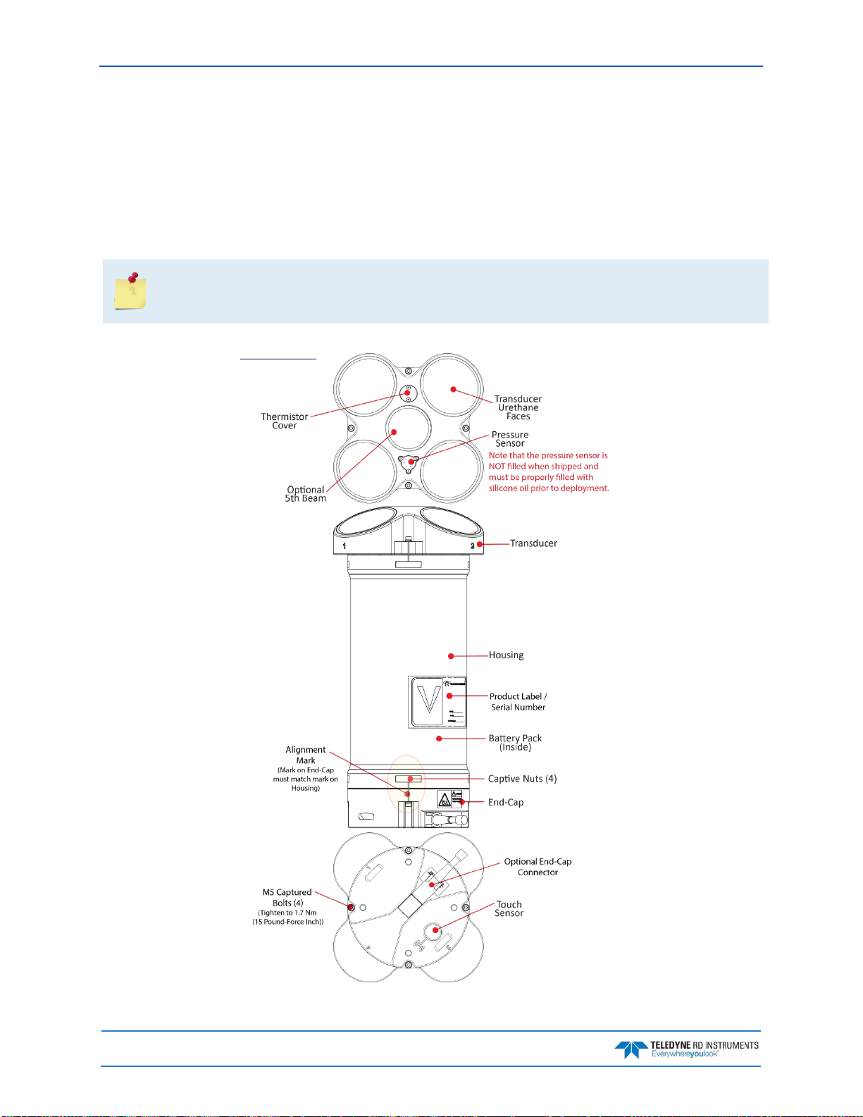
September 2017 Sentinel V SC and RT Operation Manual
Page 2 EAR-Controlled Technology Subject to Restrictions Contained on the Cover Page.
Sentinel V Features
The Sentinel V is designed for several-month autonomous current profile deployment from temporary or
permanent mounting in the ocean, near-shore, harbors, and lakes.
The Sentinel V Series ADCP consists of an ADCP, battery pack or individual D cell batteries, microSDHC
memory card, and software. Both battery capacity and memory can be increased with upgrades for longer
deployments. The Sentinel V Series ADCP requires the addition of a Windows® compatible computer to
configure the ADCP and replay collected data.
Figure 1 and Figure 2 only show two of the options and models available with the Sentinel V
Series ADCP (see
Available Options
).
After a deployment, systems need to be cleaned thoroughly before the touch sensor will work.
Figure 1. Sentinel V100 5 Beam Overview with Battery Pack and Optional End-Cap Connector
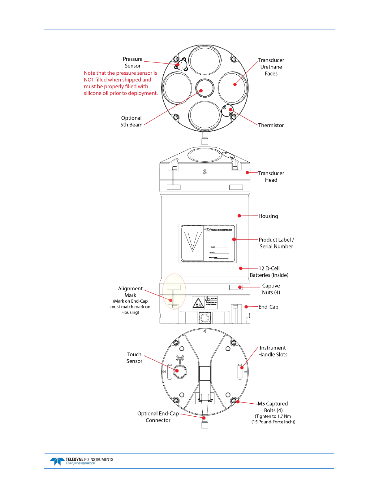
Sentinel V SC and RT Operation Manual September 2017
EAR-Controlled Technology Subject to Restrictions Contained on the Cover Page. Page 3
Figure 2. Sentinel V20 with D Cell Batteries and Optional End-Cap call out beam numbers
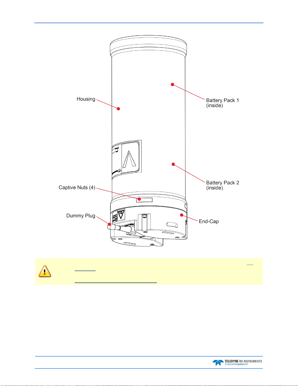
September 2017 Sentinel V SC and RT Operation Manual
Page 4 EAR-Controlled Technology Subject to Restrictions Contained on the Cover Page.
Figure 3. External Battery Case Overview
The External Battery Case holds two battery packs that are shipped inside the case but not
connected. Connect BOTH batteries and seal the external battery case before deployment. It
is necessary to remove the top battery in order to connect the bottom battery cable. See
Replacing the External Battery Case Packs for details.
This manual suits for next models
1
Table of contents
Other Teledyne RD Instruments Marine Equipment manuals


Popular Marine Equipment manuals by other brands


knudsen
knudsen 320N user manual

EMS
EMS FC-171-003 installation guide

auto maskin
auto maskin Marine Pro 400 Series Quick installation guide

NASA Marine
NASA Marine CLIPPER SPEED AND DISTANCE LOG manual

Webasto
Webasto BlueCool S Series installation instructions

Conrad Electronic
Conrad Electronic Speaka 130 operating instructions