NASA Marine CLIPPER SPEED AND DISTANCE LOG User manual

SPEED TOTAL
TRIP
ILLUM
CLIPPER LOG
CLIPPER
SPEED
AND
DISTANCE
LOG
23.5
SPEED
LKNOTS

INTRODUCTION
INSTALLING THE DISPLAY
INSTALLING THE PADDLE WHEEL
GETTING STARTED
RESETTING THE TRIP DISTANCE TO ZERO
SWITCHING BETWEEN NAUTICAL AND STATUTE MILES
DISPLAYING AVERAGE READINGS
CALIBRATION EXAMPLE
RETURNING TO NORMAL OPERATING MODE
REMOTE REPEATER FACILITY
CHANGING THE OPERATING MODE
BACKLIGHT SETTING
DISPLAYING SPEED
DISPLAYING TRIP DISTANCE
DISPLAYING THE TRIP DISTANCE
CHANGING THE UNITS OPERATING CONFIGURATION
CHANGING THE CALIBRATION
2
2
3
5
5
6
7
7
8
9
10
11
11
12
13
14
14
1

INTRODUCTION
The Clipper Speed and distance log is supplied complete with
display unit, paddle wheel assembly, skin fitting and blanking cap.
It is intended for operation from 12V ship’s supply, although,
because of its low power consumption, it can be run from an
external dry battery.
INSTALLING THE DISPLAY
Select a convenient position for the display on a panel or bulk-
head.
The site must be flat and the cavity behind the panel must
remain dry at all times. (The cable entry is deliberately not
sealed to ensure adequate ventilation. This prevents misting of
the display).
Cut a hole in the panel 87mm wide and 67mm deep. Bring the
wiring through the hole in the panel and connect the black wire
to negative and red to positive. (See Figure 1). It is wise to use a
fused supply to provide protection should a fault occur. The
current consumption is very small, so any supply with at least a
1/4 amp fuse is more than adequate.
NEGATIVE
SUPPLY
RED
BLACK
2
Figure 1 - Wiring Installation
FUSED
POSITIVE
SUPPLY
SPEED TOTAL
TRIP
ILLUM
BLUE
NMEA
OUTPUT

Unscrew and remove the two wing nuts from the rear of the
instrument and remove the stainless steel clamping bracket. Fit the
“O” ring seal into the groove in the panel mounting face of the
instrument. Ensure that it is correctly lying in its groove before
fitting the instrument to the panel, which provides the watertight
seal for the display.
Fit the instrument into the panel, fit the stainless clamp over the
studs, fit and tighten the two wing nuts finger tight only.
It is important that the O-ring rubber seal makes good contact with
the panel to prevent water getting behind the unit and entering the
cavity behind the panel.
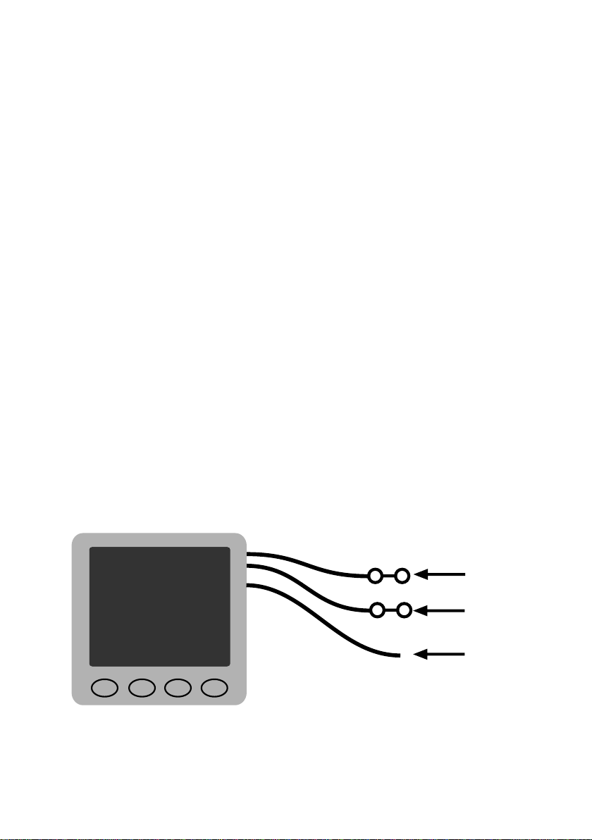
It is good practice to run the cables vertically downwards from the
unit, even if they later have to rise to connect to the vessel’s
supplies. Doing so prevents any water that might get onto the
cables from running back along the cables and into the unit.
INSTALLING THE PADDLE WHEEL
The paddle wheel should be installed at a point in the hull where:-
It is immersed at all attitudes under power or sail.
The blades of the paddle wheel are presented with a
smooth flow of water corresponding to the vessel’s speed
through the water. On displacement hulls this is usually
about amidships, but on planing hulls it should be as far aft
as possible.
It should be easily accessible in the bilges for cleaning and
laying up. A blanking cap is provided to seal the skin fitting
when the paddle wheel is removed.
It is not vulnerable to damage from unforgiving surfaces such
as trailers and lifting slings.
3
(a)
(b)
(c)
(d)

4
With the vessel out of water, drill a hole of 42mm diameter through
the hull to take the paddle housing and use conventional methods
for sealing. It is advisable to avoid the use of mastic materials - use
a form of proprietary silicon sealant.
Figure 2 - Paddle Housing Installation (Sectioned view)
The securing nut has a groove on its underside which should also
be filled with sealing compound. Take care not to over
tighten this nut. After the sealing compound has set, wipe off
the excess and encapsulate the whole assembly in G.R.P. as
shown on Figure 2. Take care to ensure that a minimum of
20mm of thread is clear at the top of the paddle housing.
The paddle wheel unit can now be slid into the housing so that it
is exposed to the water flow, with the arrow pointing forward along
the centre line of the vessel. It is recommended that a little silicon
grease is smeared over the rubber O-ring to keep the unit free.
Tighten the retaining nut onto the top of the housing, and plug the
cable into the ‘paddlewheel’ socket on the display. For added
protection it is again recommended that the plug is lightly covered
with silicon grease.
HULL
20mm
MINIMUM
SECURING
NUT
SILICONE
SEALANT
Housing
G.R.P.
42mm
Hole for paddle wheel unit
NOT TO SCALE

5
SPEED TOTAL
TRIP
ILLUM
12.3
SPEED
LKNOTS
GETTING STARTED
When the Clipper Distance & Log is first turned on, it automatically
performs a number of self-test processes, and after a brief delay
switches on the backlight illumination at the factory pre-set level.
It then displays the speed in the previously selected mode of knots
or MPH (as shown on Figure 3).
The factory default settings are Nautical Miles and Speed in
Knots. The factory pre-set trip and total distances are both zero.
THOUSANDS DIGITS
DISPLAY SPEED
DISPLAY IS KNOTS
12.3 Knots measured
TRIP IS NOT SELECTED
TOTAL IS NOT SELECTED
SWITCH TO DISPLAY
TOTAL DISTANCE
RATE
INDICATOR
N.MILES SHOWS
in TRIP or TOTAL
BACKLIGHT
BRIGHTNESS
CHANGE BACKLIGHT
BRIGHTNESS
SWITCH TO DISPLAY
SPEED
SWITCH TO DISPLAY
TRIP DISTANCE
Figure 3-Initial Display
It is easy to change the displayed readings at any time, by simply
pressing each key as described below. The unit maintains full
measurements precision at all times whatever display mode is
chosen.
CHANGING THE OPERATING MODE

6
SPEED TOTAL
TRIP
ILLUM
5.2
SPEED
LKNOTS
BACKLIGHT SETTING
To set the display back light press the ILLUM key.
Pressing ILLUM whilst `L` is shown on the display will
gradually decrease the illumination. Pressing ILLUM whilst
`H` is shown will gradually increase the illumination.
A brief press of ILLUM will roster between ‘L’ and ‘H’.
In common with all the other settings in the unit, the backlight
setting is stored even when the unit is switched off, so that it
returns to the chosen setting again whenever the unit is
switched on.
Figure 4- Backlight Setting

7
SPEED TOTAL
TRIP
5.2
SPEED
KNOTS
ILLUM
L
DISPLAYING SPEED
Figure 5- Speed Display
DISPLAYING TRIP DISTANCE
If it is desired to display speed, press the button marked SPEED.
The display changes to that shown on Figure 5, and the present
speed is displayed.
The acceleration bars below the middle digit (See Figures 4 and 5)
show whether the speed is reducing (left arrow lit), the same
(central bar lit), or is increasing (right arrow lit). These acceleration
bars are shown in the distance display modes as well as the speed
display mode.
If it is desired to display Trip distance, press the button marked TRIP.
The word TRIP is displayed as shown on Figure 6. The trip
distance is always measured in 0.1 miles or nautical miles,
depending on the setting of the unit (the setting can be changed if
desired, see the section CHANGING THE UNIT`S OPERATIONAL
CONFIGURATION, overleaf). Figure 6 shows the display as it would

8
RESETTING THE TRIP DISTANCE TO ZERO
The trip distance is stored in the unit even when it is switched off.
The trip distance can be reset to zero at any time by pressing the
TRIP button once to get to the trip display, and then pressing TRIP
again continuously. If the button is kept steadily pressed, a number
5 is shown, then 4, then 3, then 2, then 1, then zero. The trip
distance is reset when the count reaches zero. If you change your
mind about resetting the distance, remove your finger from the trip
button before the count falls to zero, whereupon the display returns
be when nautical miles is selected. Whenever the trip distance
exceeds 99.9, the number to the right of the decimal is still stored
in the unit, but the display changes to show whole miles, and the
decimal point is removed.
When the trip distance exceeds 999.9 (nautical miles or statute
miles, whichever is selected). the trip counter rolls over to 0.00
again.
Figure 6- Trip Display
SPEED TOTAL
TRIP
48.6
N.MILES TRIP
ILLUM
L

9
to the original trip reading. If the finger is left on the TRIP button
after zero is displayed, F (for Finished) is shown to remind you that
the trip distance clear is cleared. Normal operation of the trip
reading is resumed when the finger is lifted.
Note that any fractional distance in the trip distance when it is
cleared is stored for adding to the total when new trip distances are
measured. This is so there is no loss of total distance if frequent
trip resets are done
Figure 7- Total Distance Display
SPEED
105
N.MILES
ILLUM
L
DISPLAYING TOTAL DISTANCE
Total distance is stored only in whole miles or nautical miles,
depending on the setting of the unit ( see below), If it is desired to
display Total distance, press the button marked TOTAL. The
accumulated distance is displayed, and the word TOTAL shown
(see Figure 7). If the total distance is more then 999. the thousands
(with 000 following the number) are shown at the top left of the
display, which is showing 2105 nautical miles total on Figure 6.
2000
TOTAL
TRIP
TOTAL

10
TOTAL
Set
Figure 8 - Configuration Setting Display
SPEED TRIP
CHANGING THE UNIT`S OPERATIONAL
CONFIGURATION
Configuration describes the settings held permanently in the unit to
affect how it operates. To get into the configuration mode, press
and keep held pressed the ILLUM button while the unit is switched
on. When the button is released, the word “SET” is displayed (see
Figure 8).
Pressing ILLUM again returns the unit to its normal operating
mode, as stored before it was switched off, but with any new
settings also active and stored permanently. Any of the following
changes can be made from the “SET” configuration mode, which is
ended by the press on the ILLUM button to return to normal
operation.
If the total distance logged is greater then 9999, the display rolls
over to 0 again. Whenever the total distance is less than 1000,
none of the thousands digits are displayed.
ILLUM
F

11
SWITCHING BETWEEN NAUTICAL AND STATUTE MILES
The distance setting can be switched between statute miles and
nautical miles (and back again as often as needed) for both trip and
total distances. Press the SPEED button to switch between the two
modes. When nautical miles are selected, the words N.MILES are
displayed, and the unit displays knots when showing speed. When
statute miles are selected, the unit displays MPH when showing
speed. Switching between the two distance settings does not reset
the stored trip and total distances, which are shown in the correct
units when the normal display mode is chosen.
DISPLAYING AVERAGED READINGS
It is sometimes preferable to display averaged speed readings
instead of instantaneous measurements. When averaged speed is
displayed, the speed shown is the short-term average of several
readings, whereas in fast display mode, the reading changes
whenever there is a change in measurement. Using averaged
readings reduces the variability of the displayed speed whenever
small speed changes occur. The display mode is switched between
Fast and Averaged by pressing the TRIP and TOTAL keys
together, as shown on Figure 9. The letter F (for Fast) or A (for
Averaged) shows which display mode will be used when speed is
being measured.

12
ILLUM
F
TOTAL
Set
SPEED TRIP ILLUM
A
TOTAL
Set
SPEED TRIP
Figure 9 -Switching between Fast and Averaged
speed display modes
CHANGING THE CALIBRATION
The calibration factor determines the number of revolutions of the
paddle wheel required to represents 0.1 miles or nautical miles. The
calibration of the unit is set up in the factory and the value is stored
in the unit’s memory. However, the type of hull and the position of
the paddle may affect the performance and cause the speed (and
distance) to over-read or under-read.
Press the TRIP button to see the calibration factor, which is pre-set
to 100 in the factory, to give correct readings in free flow conditions.
The same factor is used for speed and distance measurements. The
facror can be increased to 150% or decreased to 70% in 1% steps.

Any changes are automatically applied to both speed and distance
measurements, and are always permanently stored in the unit even
when it is switched off.
If the factory-fresh unit (with a pre-set calibration factor of 100) is
found to under-read by, for example, 6% the calibration factor must
be increased by 6% to 106 to corect the under reading, The
calibration factor is increased by pressing the TOTAL button, and
decreased by pressing the SPEED button.
The general rule is that if the unit over-reads, the factor must be
reduced, and if it under reads, the factor must be increased. The
percentage error in the readings is the same percentage change
which must be entered. Any changes affect both speed and
distance correctly.
When the correct calibration factor has been entered, press TRIP
to return to the “SET” display, and to store the new calibration
factor for future use.
13
CALIBRATION EXAMPLE
Calibration is never easy because of the effects of currents and tides.
Because the unit measures the distance travelled through the water,
there can be significant errors in measured speed and distances
over the ground if currents are flowing. Calibration can be done by
measuring a test speed with the unit and comparing its reading with a
known speed. Another method is to traverse a know distance
(preferably twice in opposite directions to cancel the effect of currents)
and to compare the unit’s measurement with the known distance.
However, suppose, for example, a go-and-return test distance
measured by the unit was found to be 12.5 miles, and the distance is
known( from charts) to be 11.9 miles. The unit is over-reading. Doing
the division (measured divided by known) gives 100 X (12.5/11.9) =
105. This value is the effective calibration factor. To Correct the over-
reading, the unit`s calibration factor must be reduced by 5 to force
the unit`s calibration to match the outside world.

14
RETURNING TO NORMAL OPERATING MODE
Press the ILLUM button to return the unit to normal
measurements of speed in the mode which has been set up. All
the settings are stored, and will return again whenever the unit is
switched on. Returning to configuration setting from normal
operation is not available. if further configuration changes are
desired, they can be made onyl by swithcing the unit off and then
on again with ILLUM pressed during the start-up time, as
described above.
Get into configuration mode, and press TRIP. Suppose the
calibration factor is already set to the factory preset value of 100.
To reduce it by 5, press the SPEED Button 5 times to reduce the
unit`s calibration factor to 95 (which is 5 less than the original
calibration factor of 100). Likewise, if the calibration factor has
previously been adjusted to be 104, pressing the SPEED button
five times will reduce the factor to 99 to make a 5% reduction in the
calibration factor.
Press TRIP to store the new calibration factor, and return the unit to
the “SET” configuration mode. Note that the new calibration factor
applies ony to new measurements. It does not apply
retrospectively to any measurements already made and stored in
the trip and distance stores.
REMOTE REPEATER FACILITY
A repeating display unit is available for use with the Clipper speed
and distance log.

15
NMEA OUTPUT
The Clipper Log has an NMEA output version 0183 sending
sentences $VWVHW and $VWVLW. The blue lead is the
NMEA output positive.
CLIPPER LOG REPEATER
Connect the Clipper Log Repeater as follows:
Red wire to positive (+12V)
Silver/Black wire to negative
Blue wire to Blue wire on Clipper Log master unit (NMEA)
The log repeater repeats all information from the Clipper log
master unit.
To set the display back light press the ILLUM key.
Pressing ILLUM whilst `L` is shown on the display will
gradually decrease the illumination. Pressing ILLUM whilst
`H` is shown will gradually increase the illumination.
A brief press of ILLUM will roster between ‘L’ and ‘H’.
To view the master unit trip info press TRIP
To view the master unit trip info press TOTAL
Press SPEED to view the master unit speed.
No engineering settings are available.

16


Declaration of Conformity
NASA Marine Ltd declare this product is in compliance with the essential requirements of
R&TTE directive 1995/5/EC.
THIS PRODUCT IS INTENDED FOR USE ONLY ON NON SOLAS VESSELS
IMPORTANT READ THIS BEFORE
UNPACKING INSTRUMENT
LIMITED WARRANTY
Prior to unpacking this instrument read and fully understand the installation instructions.
Only proceed with the installation if you are competent to do so. Nasa Marine Ltd. will
not accept any responsibility for injury or damage caused by, during or as a result of
the installation of this product. Any piece of equipment can fail due to a number of
causes. Do not install this equipment if it is the only source of information and its failure
could result in injury or death. Instead return the instrument to your retailer for full credit.
Remember this equipment is an aid to navigation and not a substitute for proper
seamanship. This instrument is used at your own risk, use it prudently and check its
operation from time to time against other data. Inspect the installation from time to time
and seek advice if any part thereof is not fully seaworthy.
Nasa Marine Ltd. warrants this instrument to be substantially free of defects in both
materials and workmanship for a period of one year from the date of purchase.
Nasa Marine Ltd. will at its discretion repair or replace any components which fail in
normal use within the warranty period. Such repairs or replacements will be made at
no charge to the customer for parts and labour. The customer is however responsible
for transport costs. This warranty excludes failures resulting from abuse, misuse,
accident or unauthorised modifications or repairs. In no event shall Nasa Marine Ltd.
be liable for incidental, special, indirect or consequential damages, whether resulting
from the use, misuse, the inability to correctly use the instrument or from defects in
the instrument. If any of the above terms are unacceptable to you then return the
instrument unopened and unused to your retailer for full credit.
Name
Address
Dealer Name
Address
Date of Purchase
Proof of purchase may be required for warranty claims.
Nasa Marine Ltd.
Boulton Road, Stevenage, Herts SG1 4QG England
Table of contents
Other NASA Marine Marine Equipment manuals
Popular Marine Equipment manuals by other brands

Quicksilver
Quicksilver 88688A25 Installation, operation and maintenance instructions

Bosch
Bosch FNM-420V-A-WH installation guide

WÄRTSILÄ
WÄRTSILÄ RadaScan RESPONDERS 3 Series user guide

Kongsberg
Kongsberg EM 3002 Product description

VDO
VDO Logic Close Hauled Installation and operating instructions

SGS
SGS UNS20500 Quick user guide