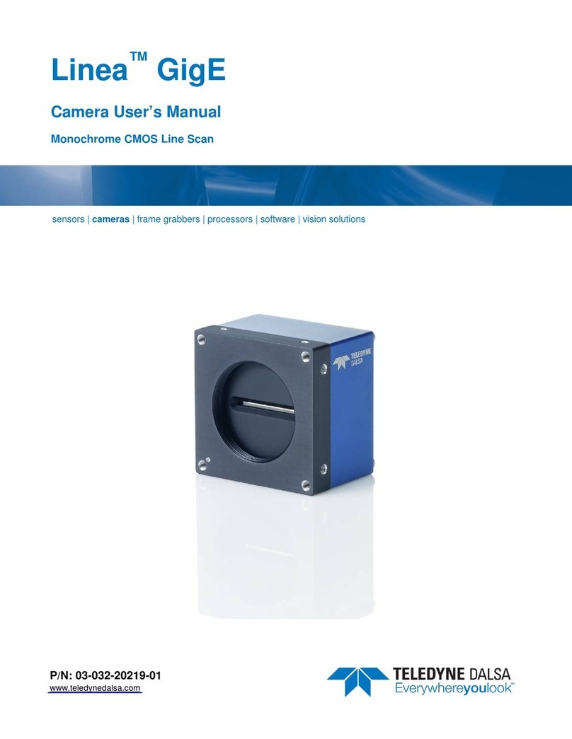
Teledyne Linea GigE 2K User manual

Notice
© 2015 Teledyne DALSA
All information provided in this manual is believed to be accurate and reliable. No
responsibility is assumed by Teledyne DALSA for its use. Teledyne DALSA reserves the right
to make changes to this information without notice. Reproduction of this manual in whole or
in part, by any means, is prohibited without prior permission having been obtained from
Teledyne DALSA.
Microsoft and Windows are registered trademarks of Microsoft Corporation in the United
States and other countries. Windows, Windows 7, Windows 8 are trademarks of Microsoft
Corporation.
All other trademarks or intellectual property mentioned herein belong to their respective
owners.
Document Date: March 30, 2015
Document Number: 03-032-20219-00
About Teledyne DALSA
Teledyne DALSA is an international high performance semiconductor and electronics
company that designs, develops, manufactures, and markets digital imaging products and
solutions, in addition to providing wafer foundry services.
Teledyne DALSA Digital Imaging offers the widest range of machine vision components in
the world. From industry-leading image sensors through powerful and sophisticated
cameras, frame grabbers, vision processors and software to easy-to-use vision appliances
and custom vision modules.

Linea GigE Series Camera Contents 1
Contents
LINEA™ GIGE SERIES OVERVIEW..................................................................5
DESCRIPTION .............................................................................................. 5
Linea GigE Application Advantages.......................................................... 6
Linea GigE with TurboDrive.................................................................... 6
Linea GigE Firmware............................................................................. 6
PART NUMBERS AND SOFTWARE REQUIREMENTS ...................................................... 7
GIGEVISION SAPERA APPLICATION DESCRIPTION .................................................... 8
CAMERA SPECIFICATIONS OVERVIEW ................................................................... 9
Compliance, EMI Certifications ..............................................................10
SENSOR PERFORMANCE:.................................................................................11
Sensor Specifications ...........................................................................11
Spectral Responsivity: .........................................................................12
Effective Quantum Efficiency: ...............................................................12
CONNECTING THE LINEA GIGE CAMERA .....................................................13
GIGENETWORK ADAPTER OVERVIEW..................................................................13
PAUSE Frame Support..........................................................................13
CONNECT THE LINEA GIGECAMERA ...................................................................13
Connectors.........................................................................................14
LED Indicators ....................................................................................15
Network Status Indicators...........................................................................15
Camera Status LED Indicator ......................................................................15
LED States on Power Up .............................................................................16
Linea GigE IP Configuration Sequence ....................................................16
Supported Network Configurations ...............................................................16
PREVENTING OPERATIONAL FAULTS DUE TO ESD ....................................................17
USING LINEA GIGE WITH THE SAPERA API.................................................18
NETWORK AND COMPUTER OVERVIEW .................................................................18
INSTALLATION ............................................................................................19
Procedure ..........................................................................................19
Camera Firmware Updates....................................................................19
GigE Server Verification .......................................................................20
GigE Server Status ..............................................................................20
OPTIMIZING THE NETWORK ADAPTER USED WITH LINEA GIGE .....................................21
Running the Network Configuration Tool .................................................21
QUICK STARTUP WITH CAMEXPERT.....................................................................22
About the User Defined Camera Name ...................................................23
OPERATIONAL REFERENCE..........................................................................24
USING CAMEXPERT WITH LINEA GIGECAMERAS .....................................................24
CamExpert Panes ................................................................................24
CamExpert View Parameters Option .............................................................26
Creating a Camera Configuration File in the Host .....................................26
CAMERA INFORMATION CATEGORY .....................................................................27
Camera Information Feature Descriptions ...............................................27
Camera Configuration Selection Dialog ...................................................30

2 Contents Linea GigE Series Camera
Camera Power-up Configuration ..................................................................30
User Set Configuration Management.............................................................30
SENSOR CONTROL CATEGORY...........................................................................31
Sensor Control Feature Descriptions.......................................................31
Gain and Black Level Control Details ......................................................32
Exposure Controls Details.....................................................................33
Internal Programmable Exposure .................................................................33
External Programmable Exposure.................................................................33
External Trigger Width Exposure ..................................................................34
Exposure and Readout Overlap ....................................................................34
I/O CONTROL CATEGORY................................................................................35
I/O Control Feature Descriptions ...........................................................36
I/O Module Block Diagram ....................................................................41
Trigger Overview.................................................................................41
Trigger Selector Details ..............................................................................42
Trigger Source Types .................................................................................43
Input Line Details ......................................................................................43
Output Line Details ....................................................................................44
Example of Free Run Line Mode with Frame Trigger ........................................44
Example of Line Trigger Mode......................................................................44
Example of Line Trigger plus Frame Trigger Combined ....................................45
COUNTER AND TIMER CONTROL CATEGORY ...........................................................46
Counter and Timer Control Feature Description........................................46
Counter and Timer Group Block Diagram ................................................51
Example: Counter Start Source = OFF ..........................................................51
Example: Counter Start Source = CounterEnd (itself) .....................................52
Example: CounterStartSource = EVENT and Signal (Edge Base) .......................52
Example: CounterStartSource = Signal (Level Base) Example 1 .......................53
Example: CounterStartSource = Line (Edge Base) Example 2...........................53
ADVANCED PROCESSING CONTROL CATEGORY........................................................54
Advanced Processing Control Feature Descriptions ...................................54
Flat Field Correction Overview...............................................................56
Flat Field Correction Algorithm Description ....................................................57
Information on the Sapera Flat Field Coefficients File ......................................57
Important Factors about Flat Field Processing ................................................57
How to do a FFC Setup via Sapera CamExpert.........................................58
Set up Dark and Bright Acquisitions with the Histogram Tool............................58
Flat Field Correction Calibration Procedure.....................................................59
Using Flat Field Correction ....................................................................62
CYCLING PRESET MODE CONTROL CATEGORY ........................................................62
Cycling Preset Mode Control Feature Description......................................63
Using Cycling Presets—an Example ........................................................66
Initial Example Setup .................................................................................66
Cycling Example: Changing Gain..................................................................66
IMAGE FORMAT CONTROL CATEGORY ..................................................................68
Image Format Control Feature Description ..............................................68
Pixel Size: Monochrome 12-Bit Packed ...................................................72
Binning ..............................................................................................72
Internal Test Image Generator ..............................................................73
ACQUISITION AND TRANSFER CONTROL CATEGORY ..................................................73
Acquisition and Transfer Control Feature Descriptions...............................73
Acquisition Buffering ..................................................................................75
Using Transfer Queue Current Block Count with CamExpert .............................75
Overview of Transfer Control (TransferControlMode) ................................75
Features that Cannot be Changed During a Sapera Transfer ......................77
EVENT CONTROL CATEGORY.............................................................................78

Linea GigE Series Camera Contents 3
Event Control Feature Descriptions ........................................................79
GIGEVISION TRANSPORT LAYER CONTROL CATEGORY ..............................................83
GigE Vision Transport Layer Feature Descriptions.....................................83
Defaults for devicePacketResendBufferSize .............................................88
Device UPnP Auto-Discovery Mode Details ..............................................88
Enable Windows Network Discovery .............................................................88
Accessing the Linea GigE File Memory...........................................................90
Using the Linea GigE File Memory ................................................................90
GIGEVISION HOST CONTROL CATEGORY .............................................................91
FILE ACCESS CONTROL CATEGORY .....................................................................91
File Access Control Feature Descriptions .................................................91
File Access via the CamExpert Tool ........................................................93
DEVICE STREAMING REGISTERS ........................................................................94
Start – End Command Requirements .....................................................94
NETWORK OVERVIEW & TOOLS...................................................................95
IP CONFIGURATION MODE DETAILS....................................................................95
Link-Local Address (LLA) ......................................................................95
DHCP (Dynamic Host Configuration Protocol) ..........................................96
Persistent IP.......................................................................................97
TECHNICAL SPECIFICATIONS......................................................................99
MECHANICAL SPECIFICATIONS:.........................................................................99
ADDITIONAL NOTES ON LINEA GIGEIDENTIFICATION AND MECHANICAL........................100
SENSOR ALIGNMENT SPECIFICATION................................................................. 100
CONNECTORS ...........................................................................................101
HD15 type Connector Details ..............................................................101
Mating GPIO Cable Assembly..................................................................... 101
Input Signals Electrical Specifications...................................................103
Output Signals Electrical Specifications.................................................105
COMPUTER REQUIREMENTS FOR LINEA GIGECAMERAS............................................ 106
Host PC System ................................................................................ 106
Ethernet Switch Requirements ............................................................106
IEEE 802.3x Pause Frame Flow Control ....................................................... 106
Ethernet to Fiber-Optic Interface Requirements .....................................107
EC &FCC DECLARATIONS OF CONFORMITY ........................................................108
ADDITIONAL REFERENCE INFORMATION ..................................................109
LENS SELECTION OVERVIEW ..........................................................................109
Lens Mount Types .............................................................................109
M42x1 to Nikon F Bayonet Adapter (AC LA 00115 A1-R ) ................................. 110
M42x1 to C-Mount Adapter (AC-LC-00001-00-R) ............................................ 111
Lens Image Circle Illustration..............................................................112
Additional Lens Parameters (application specific) ...................................113
OPTICAL CONSIDERATIONS............................................................................114
Illumination......................................................................................114
Light Sources ...................................................................................114
Lens Modeling................................................................................... 115
Magnification and Resolution...............................................................115
SENSOR HANDLING INSTRUCTIONS ..................................................................116
Electrostatic Discharge and the Sensor ................................................. 116
Protecting Against Dust, Oil and Scratches............................................116
Cleaning the Sensor Window...............................................................117
RUGGEDIZED RJ45 ETHERNET CABLES ..............................................................118

4 Contents Linea GigE Series Camera
TROUBLESHOOTING ..................................................................................119
OVERVIEW...............................................................................................119
Problem Type Summary .....................................................................119
Verifying Network Parameters .............................................................121
Before Contacting Technical Support .......................................................... 121
INSTALLATION ISSUES AND FUNCTIONAL PROBLEMS ...............................................121
DEVICE AVAILABLE WITH OPERATIONAL ISSUES ....................................................121
Firmware Updates .............................................................................121
Power Failure During a Firmware Update–Now What? .............................122
Cabling and Communication Issues......................................................122
Acquisition Error without Timeout Messages..........................................123
No camera exposure when expected........................................................... 123
Camera is functional but frame rate is lower than expected ........................... 123
Camera acquisition is good but frame rate is lower than expected................... 123
Camera is functional, line rate is as expected, but image is black ................... 123
Other Problems or Issues ...................................................................124
Random Invalid Trigger Events .................................................................. 124
Buffer Incomplete Error Message ............................................................... 124
Issues with Cognex VisionPro .................................................................... 124
CONTACT INFORMATION...........................................................................125
SALES INFORMATION...................................................................................125
TECHNICAL SUPPORT...................................................................................125
INDEX .......................................................................................................126

Linea GigE Series Camera Linea™ GigE Series Overview 5
Linea™ GigE Series Overview
Description
The Linea GigE Vision linescan is a new affordable single line, camera delivering both speed and
responsivity at a competitive price. This small, low power camera is designed for applications such
as materials grading and inspection, transportation safety, automated optical inspection and
general purpose machine vision.
The Linea GigE Vision camera, is one of a new series of affordable easy to use digital cameras
specifically engineered for industrial imaging applications requiring embedded image processing
and improved network integration. Linea GigE provides features to cycle a user defined sequence
of imaging setups, features providing line & frame triggers, image transfer-on-demand, all part of a
comprehensive camera package.
Linea GigE combine standard gigabit Ethernet technology (supporting GigE Vision 1.2) with
Teledyne DALSA Trigger-to-Image-Reliability, to dependably capture and transfer images from the
camera to the host PC.

6 Linea™ GigE Series Overview Linea GigE Series Camera
Linea GigE Application Advantages
Optimized, rugged design
GigE Vision 1.2 compliant
Gigabit Ethernet (GigE) interconnection to a computer via standard CAT5e or CAT6 cables
Supports connection to the host computer NIC through a GigE network switch
GigE Vision Turbo Drive Technology Module
Available in 2048 or 4096 pixel line resolutions
8 bit or 12 bit output
High line rates
2 general purpose inputs with programmable threshold
2 bidirectional I/O
2 general purpose outputs
Counter, Timer, and Events available to support imaging applications
Native Trigger-to-Image Reliability design
Visual status LEDs on camera back plate
Supported by Sapera™ LT software libraries
Camera power via HD15 GPIO connector
Support for end-of-line Metadata
Digital binning for increased sensitivity
Multiple real-time Flat Field processing available with image cycling
(i.e. shading corrections )
Supports cycling multiple exposure times for sequential images. along with other
parameters
1µs internal timer or external events can timestamp images
Provides 4 User Settings sets to store and recall camera configurations
Refer to the Operation Reference and Technical Specifications section of the manual for full
details.
Linea GigE with TurboDrive
Linea cameras include TurboDrive™ technology, delivering high speed data transfers exceeding the
GigE limit. TurboDrive uses advanced data modeling to boost data transfers up to 2 or 3 times
faster than standard GigE Vision speeds – with no loss of image quality. These breakthrough line
rates are achieved using a proprietary, patent pending process that assembles data from the
sensor to optimize throughput, simultaneously taking full advantage of both the sensor’s maximum
line rate (up to 80 kHz) and the camera’s maximum GigE data transfer speed (up to 110
Mbytes/s). TurboDrive increases system dependability and robustness by engaging Linea’s full
image capture capability—similar to Camera Link throughput on a GigE network.
Linea GigE Firmware
Firmware updates for Linea GigE are available for download from the Teledyne DALSA web site
[ www.teledynedalsa.com/imaging/support/downloads ]. Choose Linea GigE Firmware from the
available download sections, then choose the zip file download specific to your camera model.
Update the camera firmware using CamExpert (see File Access via the CamExpert Tool).

Linea GigE Series Camera Linea™ GigE Series Overview 7
Part Numbers and Software Requirements
This manual covers the Linea GigE models summarized below. New models area added to this
manual as they are released by Teledyne DALSA. See “Camera Specifications” on page 9 for details
of each Linea GigE model.
Camera Resolution Pixel size Max. Line Rate Lens Mount
(treaded)
Product Number
Linea GigE 2K 2048 x 1 7.04 x 7.04 µm 80 kHz M42 x 1 LA-GM-02K08A-00-R
Linea GigE 4k 4096 x 1 7.04 x 7.04 µm 80 kHz M42 x 1 LA-GM-04K08A-00-R
Linea GigE 8k 8192 x 1 TBD
Accessories Order Number
M42 x 1 to F-mount adapter for 12mm BFD lens, heavy duty with clip AC-LA-00115-A1-R
M42 x 1 to C-mount adapter for 12 mm BFD lens AC-LC-00001-00-R
HD15 GPIO Breakout Cable Assembly AC-CA-00002-00-R
Linea Heatsink AC-MS-00108-01-R
For a list of accessories go to http://www.teledynedalsa.com/imaging/products/cameras/accessories/
Optical filters are available from http://www.midwestopticalsystems.com/
Teledyne DALSA Software Platform
Sapera LT version 7.50 – supports all firmware designs (for Windows)
includes Sapera Runtime and CamExpert
Linea GigE cameras require installation of the Sapera Network Imaging Package and
GigE Vision Imaging Driver.
Available for download
http://www.teledynedalsa.com/mv/
Sapera LT version 8.00 and later includes the Sapera Network Imaging Package
and GigE Vision Imaging Driver.
GigE Vision Turbo Drive Technology Module — improved proprietary package
allows the Linea GigE to sustain higher data transfers to the host system.
Contact Teledyne DALSA Sales for additional information.
Sapera provides everything needed to develop imaging applications.
New or alternative Linea GigE Firmware Designs Via web download
Sapera Processing Imaging Development Library
(available for Windows or Linux - sold separately):
Contact Teledyne DALSA Sales
Third Party GigE Vision Software Platform Requirements
Support of GenICam GenApi version 2.3 General acquisition and control. File access: firmware,
FFC, configuration data, upload & download.
Support of GenICam XML schema version 1.1
Support of GigE Vision 1.2 Includes end-of-line Metadata
GenICam™ support — XML camera description file Embedded within Linea GigE

8 Linea™ GigE Series Overview Linea GigE Series Camera
GigE Vision Sapera Application Description
Linea GigE cameras are 100% compliant with the GigE Vision 1.2 specification
which defines the communication interface protocol used by any GigE Vision
device. The device description and capabilities are contained in an XML file.
For more information see:
http://www.machinevisiononline.org/public/articles/index.cfm?cat=167
Linea GigE cameras implement a superset of the GenICam™ specification
which defines device capabilities. This description takes the form of an XML
device description file respecting the syntax defined by the GenApi module of
the GenICam™ specification. For more information see www.genicam.org.
The Teledyne DALSA GigE Vision Module provides a license free development platform for Teledyne
DALSA GigE hardware or Sapera vision applications. Additionally supported are Sapera GigE Vision
applications for third party hardware with the purchase of a GigE Vision Module license, or the
Sapera processing SDK with a valid license.
The GigE Vision Compliant XML device description file is embedded within Linea GigE firmware
allowing GigE Vision Compliant applications access to camera capabilities and controls immediately
after connection.
User’s Sapera
Application
Sapera LT SDK
GigE Vision
Module
GigE Server Sapera Network
Imaging Driver
CamExpert
Ethernet Network Interface Card
Network
Configuration Tool
Images
Control
GVSP
GigE Vision
Stream
Protocol
GVCP
GigE Vision
Control
Protocol
single GigE Vision
Camera
Sapera LT
Linea GigE
Package
smart DHCP
Server (optional)
Sapera
Network
Imaging
Module
Alternatively via a switch
To multiple GigE
Vision Cameras
Camera
Firmware
User
Manuals

Linea GigE Series Camera Linea™ GigE Series Overview 9
Camera Specifications Overview
Camera Controls
Synchronization Modes Free running, External triggered, Software trigger through Ethernet
Exposure Modes Programmable in increments of 1µs
minimum (in µs) is model specific
maximum is 3 milliseconds
Pulse controlled via Trigger pulse width.
Trigger Inputs
(used as Line or Frame triggers)
RS422, and 3.3V to 24V typical
Debounce range from 0 up to 255 µs
Frame Triggers have a programmable delay up to 2,000,000µs for 128 objects max.
Strobe Outputs
Aligned to the start of exposure with a programmable delay, duration and polarity
(using “start of exposure on output line source” feature)
Features
Flat Field Correction 1 Factory FFC plus 4 User Defined FFC
Binning Digitally based: Horizontal & Vertical (2 and 4 pixel)
Gain 0.0002x to 10x
Counter and Timer 2 Counters, and 2 Timers.
User programmable, acquisition independent, with event generation.
Timestamp 1µs internal timer (external signaling planned with a future release)
Metadata Support End-of-Line Metadata
Test image Internal generator with choice of static patterns
User settings Select factory default or either of two user camera configurations
Onboard Memory
Minimum Reserved Data Buffer 200 MB
Reserved Packet Resend Buffer 24 MB default (user defined feature)
Reserved Private User Buffer 4 kB
Total Memory 256 MB
Back Focal Distance
M42 x 1 mount 12 mm
M42 to Nikon F bayonet adapter 46.5 mm (34.5 mm for the F mount adapter plus 12 mm for the camera body)
M42 to C-Mount adapter 17.52 mm (5.52 mm for the C mount adapter plus 12 mm for the camera body)
Mechanical Interface
Camera Size 62(H) x 62(W) x 48(L) in mm, see “Mechanical Specifications” on page 99
Mass < 280g (no lens)
Power connector via HD15 GPIO connector
Ethernet connector RJ45
Electrical Interface
Input Voltage +12 to +24 Volts DC (+20%/- 10%)
Power Dissipation < 6 W
Operating Temperature 0 to 65°C at front plate
Relative Humidity 5% to 90% non-condensing (operating)
Output Data Configuration Gigabit Ethernet with PAUSE Frame support (as per IEEE 802.3x)
Data and Control GigE Vision compliant

10 Linea™ GigE Series Overview Linea GigE Series Camera
Compliance, EMI Certifications
Compliance Directives Standards ID Overview
EN55032 (2012) Electromagnetic compatibility of multimedia
equipment — Emission requirements
EN55011 (2009) with A1(2010) Industrial, scientific and medical equipment —
Radio-frequency disturbance characteristics —
Limits and methods of measurement
EN 61326-1 (2013) Electrical equipment for measurement, control and
laboratory use — EMC requirements —
Part 1: General requirements
EN 55024 (2010) Information technology equipment —
Immunity characteristics —
Limits and methods of measurement
CISPR 11 Industrial, scientific and medical equipment —
Radio-frequency disturbance characteristics —
Limits and methods of measurement
CE
CISPR 32 Electromagnetic compatibility of multimedia
equipment - Emission requirements
FCC Part 15, class A
RoHS Compliancy as per European directive 2004/105/EC
For an image of the Linea GigE certificate see "EC & FCC Declarations of Conformity" on page 108

Linea GigE Series Camera Linea™ GigE Series Overview 11
Sensor Performance:
The sensor description below provides a specification table and response graphics. The graph
describes the sensor response to different wavelengths of light (excluding lens and light source
characteristics). Visible light spans wavelengths between about 390 - 780 nanometers.
Wavelengths below 390 nm are termed ultra-violet while those above 780 nm. are termed infra-
red.
Sensor Specifications
Item / Feature Specification
Camera Models LA-GM-02K08A-00-R (2048) or LA-GM-04K08A-00-R (4096)
Sensor Used High speed CMOS line scan
Minimum Line Rate (internal acquisition) 100 Hz
Maximum Line Rate (internal acquisition) 80 kHz
Maximum Line Rate Output System dependent on the GigE network
Exposure Control 4 μs to 3 ms
Internal Trigger to Start of Exposure ~0.24 μs minimum (programmable exposure mode)
External Trigger to Start of Exposure ~0.30 μs minimum (programmable exposure mode)
~12.75 μs (pulse width controlled exposure mode)
Horizontal Line Time 12.5 μs
Readout Time 12.2 μs
Pixel Size 7.04 µm x 7.04 µm
Pixel Format User selectable 8-bit or 12-bit
Sensor Gain Range Default Gain value = 1.0, User selectable 1x to 10x
Output Dynamic Range >60 db (nominal gain)
Random Noise < 3.75 DN* rms (FFC enabled)
DC Offset 7 DN — 12-bit (FFC enabled)
PRNU < 1.5% @ 50% Saturation
FPN < 7 DN
SEE 12.5 nJ / cm2
NEE 11.7 pJ / cm2
Anti-blooming > 100 x Saturation
Integral non-linearity 1.5 % DN
Test Conditions
Values measured using 12-bit, 1x gain
10 kHz line rate
Light source: broadband, quartz halogen, 3250 K with 700 nm IR cut-off filter
Front plate temperature: 45° C

12 Linea™ GigE Series Overview Linea GigE Series Camera
Spectral Responsivity:
Effective Quantum Efficiency:
The quantum efficiency graph describes the fraction of photons at each wavelength that contribute
charge to the pixel.

Linea GigE Series Camera Connecting the Linea GigE Camera 13
Connecting the Linea GigE
Camera
GigE Network Adapter Overview
If the computer to be used with the Linea GigE camera does not have a Gigabit network adapter or
second built in Gigabit NIC, a Gigabit Network Interface adapter card (NIC) needs to be installed.
Typically under Windows, the Gigabit NIC is recognized automatically when Windows boots.
With any high performance Gigabit NIC adapter, review the NIC documentation concerning any
special driver required for your specific operating system. When adding a NIC adapter to a
computer, Teledyne DALSA engineering has seen cases where a PCI Express bus Gigabit NIC has
better overall performance than the same NIC hardware in PCI bus format.
PAUSE Frame Support
The Linea GigE supports the Gigabit Ethernet PAUSE Frame feature as per IEEE 802.3x. PAUSE
Frame is the Ethernet flow control mechanism that temporarily stops data transmission on the
network. The PAUSE Frame feature can help a NIC that doesn’t have enough buffering to handle
full-speed reception. This requires that the flow control option in the NIC property settings and the
Ethernet switch settings must be enabled.
Note that this problem is not as common with advances in computer bus speeds and memory
sizes. PAUSE Frame support is typically required to manage network traffic within an Ethernet
switch when multiple cameras are simultaneously used. Using PAUSE Frame will require the user to
test various values of Jumbo Frames, to determine the best data throughput. Therefore the
downside to managed network traffic is that the Pause Frame control will reduce the absolute
maximum transfer bandwidth possible on the network.
Connect the Linea GigE Camera
Connecting a Linea GigE to a network system is independent of whether the Teledyne DALSA
Sapera LT package or a third party GigE Vision development package is used.
Before connecting power to the camera, test all power supplies. Power supplies must meet the
requirements defined in section "Input Signals Electrical " on page 103. Apply power to the
camera.
Connect Linea GigE to the host computer GigE network adapter or to the Ethernet switch via a
CAT5e or CAT6 Ethernet cable. Note: cable should not be less than 1 meter (3 feet) long or
more than 100 meters (328 feet) long.
Once communication with the host computer is started the automatic IP configuration sequence
will assign an LLA IP address as described in section "Linea GigE IP Configuration Sequence" on
page 16, or a DHCP IP address if a DHCP server is present on your network.
Check the diagnostic LED which will be initially red then switch to flashing blue while waiting for
IP configuration. See "Camera Status LED " on page 15 for Linea GigE LED display descriptions.

14 Connecting the Linea GigE Camera Linea GigE Series Camera
The factory defaults for Linea GigE is Persistent IP disabled and DHCP enabled with LLA always
enabled as per the GigE Vision specification. For additional information see "IP Configuration
Mode Details" on page 95. See the next section "Connectors" on page 14 for an overview of the
interface.
Connectors
The Linea GigE has two connectors:
A single RJ45 Ethernet connector for control and video data transmitted to/from the host
computer Gigabit NIC. See "Ruggedized RJ45 Ethernet Cables" on page 118 for secure cables.
A HD15 connector for camera power, plus trigger, strobe and general I/O signals. Teledyne
DALSA provides an optional breakout cable See Mating GPIO Cable Assembly. See “HD15 type
Connector Details” on page 101 for connector pinout specifications.
The following figure of the Linea GigE back end shows connector and LED locations. See
"Mechanical Specifications" on page 99 for details on the connectors and camera mounting
dimensions.
Linea GigE – Rear View

Linea GigE Series Camera Connecting the Linea GigE Camera 15
LED Indicators
The Linea GigE has one multicolor LED to provide a simple visible indication of camera state and
the RJ45 Ethernet connector has two LEDs for network status conditions. These are described
below.
Network Status Indicators
The Linea GigE RJ45 Ethernet connector has two LEDS which display standardized information,
defined as follows:
Ethernet Connector LEDs Color Description
Left LED (Connection indicator) Amber Connected to a network
Off Not Connected to a network
Right LED (Link/Activity indicator) Green Blinking – There is activity on the port
Off No data is currently being transferred
Camera Status LED Indicator
The camera is equipped with one LED to display the operational status of the camera. When more
than one condition is active, the LED color indicates the condition with the highest priority (such as
an acquisition in progress has more priority than a valid IP address assignment).
Once the Linea GigE is connected to a network, the Status LED will turn to steady blue when the IP
address is assigned. Only at this time will it be possible by the GigE Server or any application to
communicate with the camera. The following table summarizes the LED states and corresponding
camera status.
LED State Definition
LED is off No power to the camera
Steady Red Initial state on power up before flashing.
Remains as steady Red only if there is a fatal error.
Camera is not initialized **
Flashing Red Initialization sequence in progress
** Wait a few minutes for the camera to reboot itself.
Steady Red + Flashing
Blue
Fatal Error. If the camera does not reboot itself contact Technical Support.
Slow Flashing Blue Ethernet cable disconnected. The camera continuously attempts to assign
itself an IP address.
Fast Flashing Blue File Access Feature is transferring data such as a firmware update or FCC
transfer, etc.
Steady Blue IP address assigned;
no application connected to the camera
Steady Green Application connected
Flashing Green Acquisition in progress. Flashing occurs on frame acquisition but does not
exceed a rate of 100ms for faster frame rates.
Note: Even if the Linea GigE has obtained an IP address, it might be on a different subnet than the NIC it is
attached to. Therefore, if the Linea GigE LED is blue but an application can not see it, this indicates a network
configuration problem. See the troubleshooting section in this manual.

16 Connecting the Linea GigE Camera Linea GigE Series Camera
LED States on Power Up
The following LED sequence occurs when the Linea GigE is powered up connected to a network
with installed GigE Vision software.
Flashing Red
initialization Flashing Blue
waiting for IP Blue
IP assigned Green
application
connected
Red
power connected
Linea GigE IP Configuration Sequence
The IP (Internet Protocol) Configuration sequence to assign an IP address is executed
automatically on camera power-up or when connected to a network. As a GigE Vision compliant
device, Linea GigE attempts to assign an IP address as follows.
For any GigE Vision device, the IP configuration protocol sequence is:
Persistent IP (if enabled)
DHCP (if a DHCP server is present such as the Teledyne DALSA Smart DHCP server)
Link-Local Address (always enabled)
The factory defaults for Linea GigE is Persistent IP disabled and DHCP enabled with LLA always
enabled as per the GigE Vision specification. For additional information see "IP Configuration Mode
Details" on page 95.
Supported Network Configurations
The Linea GigE obtains an IP address using the Link Local Address (LLA) or DHCP, by default. A
LLA IP address is obtained typically in a few seconds with Microsoft Windows Vista/7/8. If required,
a persistent IP address can be assigned (see "Running the Network Configuration Tool" on page
21).
Preferably, a DHCP server is present on the network, where the Linea GigE issues a DHCP request
for an IP address. The DHCP server then provides the IP address. The Teledyne DALSA Network
Configuration tool, installed with the Teledyne DALSA Network Imaging Package, provides a DHCP
server which is easily enabled on the NIC used with the Linea GigE (refer to the Teledyne DALSA
Network Imaging Package user's manual).
The LLA method, if used, automatically assigns the camera with a randomly chosen address on the
169.254.xxx.xxx subnet. After an address is chosen, the link-local process sends an ARP query
with that IP onto the network to see if it is already in use. If there is no response, the IP is
assigned to the device, otherwise another IP is selected, and the ARP is repeated. Note that LLA is
unable to forward packets across routers.

Linea GigE Series Camera Connecting the Linea GigE Camera 17
Preventing Operational Faults due to ESD
Linea GigE camera installations which do not protect against ESD (electrostatic discharge) may
exhibit operational faults. Problems such as random packet loss, random camera resets, and
random loss of Ethernet connections, may all be solved by proper ESD management.
The Linea GigE camera when used with a simple power supply and Ethernet cable, is not properly
connected to earth ground and therefore is susceptible to ESD caused problems. An Ethernet cable
has no ground connection and a power supply's 0 volt return line is not necessarily connected to
earth ground.
The following methods, either individually or together, will reduce or prevent ESD problems:
Method 1: Use a shielded power supply. The camera case is now properly connected to earth
ground and can withstand high ESD events .
Method 2: Use a shielded Ethernet cable to provide a ground connection from the controlling
computer, to the Linea GigE.
Method 3: Mount the camera on a metallic platform with a good connection to earth ground.
Method 4: Avoid running the Ethernet cable close to or parallel to AC power lines.

18 Using Linea GigE with the Sapera API Linea GigE Series Camera
Using Linea GigE with the
Sapera API
A Linea GigE camera installation with the Teledyne DALSA Sapera API generally follows the
sequence described below. Detailed installation instructions follow this overview.
Network and Computer Overview
Linea GigE needs to connect to a computer with a GigE network adapter, either built in on
the computer motherboard or installed as a third party PCI adapter. See the previous section
Connecting the Linea GigE Camera.
Laptop computers with built in GigE network adapters may still not be able to stream full
line rates from Linea GigE, especially when on battery power. Thorough testing is required with
any laptop computer to determine the maximum frame rate possible (refer to the Teledyne
DALSA Network Imaging Package user's manual).
Linea GigE also can connect through a Gigabit Ethernet switch. When using VLAN groups,
the Linea GigE and controlling computer must be in the same group (refer to the Teledyne
DALSA Network Imaging Package user's manual).
If Linea GigE is to be used in a Sapera development environment, Sapera LT 7.50 needs to
be installed, either before or after the GigE Vision Module software package.
If using Sapera LT 8.0 or later, all GigE Vision support is automatically installed.
For maximum sustained data transfers to host, install the Teledyne DALSA GigE Vision Turbo
Drive Technology module even if using Sapera LT 8.0.
If Linea GigE will be used in a third party GigE Vision Compliant environment, Sapera or
Sapera runtime is not required and you need to follow the installation instructions of the third
party package.
The Windows Firewall exceptions feature is automatically configured to allow the Sapera GigE
Server to pass through the firewall.
Computers with VPN software (virtual private network) may need to have the VPN driver
disabled in the NIC properties. This would be required only on the NIC used with the Linea
GigE. Testing by the user is required.
Once a Linea GigE is connected, look at the small camera icon added to the Windows tray (next
to the clock). Ensure the camera has been found (right click the icon and select Status) Note
that in Windows 7, the icon remains hidden until a camera is connected.
A new Linea GigE camera may require a firmware update. The File Selector feature is used to
select a firmware file. See the CamExpert procedure "File Access via the CamExpert Tool" on
page 93 for additional information.
Use CamExpert (installed either with Sapera or Sapera runtime) to test the installation of the
Linea GigE camera. Set the Linea GigE to internal test pattern. See "Internal Test Image
Generator" on page 73.
Set up the other components of the imaging system such as light sources, camera mounts,
optics, encoders, trigger sources, etc. Test with CamExpert.
Other manuals for Linea GigE 2K
1
This manual suits for next models
2
Table of contents
Other Teledyne Camera Accessories manuals
Popular Camera Accessories manuals by other brands

Aegis
Aegis ABL-52030P user manual

William Optics
William Optics WD-CF-DIG2-D Cleaning instructions

Sennheiser
Sennheiser MKE 440 quick guide

Vicon
Vicon V402 Series Instructions for installation and operation

Zeiss
Zeiss T* ZM-Mount Lenses instruction manual

Deka
Deka unigy Installation and operating instructions