Teledyne T3AFG40 User manual
T3AFG40 / T3AFG80 / T3AFG120
Function / Arbitrary Waveform Generators
Quick Start Guide
Version 1.1
September, 2018

Contents
General Safety Summary..........................................................................................1
Adjustment Handle....................................................................................................2
The Front Panel .................................................................................................... 3
Back Panel ............................................................................................................ 8
Touch Screen Display .......................................................................................... 10
Built-In Help System …......................................................................................... 12
© 2018 Teledyne LeCroy, Inc. All rights reserved.
Teledyne Test Tools is a brand and trademark of Teledyne LeCroy, Inc. Other
product or brand names are trademarks or requested trademarks of their respective
holders. Specifications, prices, availability and delivery subject to change without
notice.

Quick Start 1
General Safety Summary
Read the following precautions carefully to avoid any personal
injuries, or damage to the instrument or products connected to it.
Use the instrument only as specified.
Use only the power cord supplied for the instrument.
Ground the instrument. The instrument is grounded through the
ground conductor of the power cord. To avoid electric shock,
always connect to grounded outlets. Make sure the instrument is
grounded correctly before connecting its input or output terminals.
Do not connect external signals. The BNC connector is used to
output the generated waveforms only. No external signals should
be connected to the BNC, or the instrument may be damaged.
Observe all terminal ratings and signs on the instrument to
avoid fire or electric shock. Before connecting to the instrument,
read the manual to understand the input/output ratings.
Do not operate with suspected failures. If you suspect that the
instrument is damaged, contact the Teledyne LeCroy service
department immediately.
Do not operate in wet/damp conditions.
Do not operate in an explosive atmosphere.
Keep the surface of the instrument clean and dry.
Avoid touching exposed circuits or wires. Do not touch
exposed contacts or components when the power is on.
Do not operate without covers. Do not operate the instrument
with covers or panels removed.
Use only the fuse specified for the instrument.
Use proper overvoltage protection.
Observe ventilation requirements. Ensure good ventilation.
Check the vent and fan regularly to prevent overheating.

2 Quick Start
Safety Terms and Symbols
The following terms may appear on the instrument:
DANGER:
Direct injury or hazard may occur.
WARNING:
Potential injury or hazard may occur.
CAUTION:
Potential damage to instrument/property may occur.
The following symbols may appear on the instrument:
CAUTION
Risk of
injury or
damage.
Refer to
manual.
WARNING
Risk of
electric
shock or
burn
Earth
Ground
Terminal
Protective
Conductor
Terminal
Frame or
Chassis
Terminal
ON/
Standby
Power
Alternating
Current
Operating Environment
Temperature: 0 °C to 40 °C
Relative Humidity: 5 to 90% RH at ≤ 30 °C
Altitude: ≤ 3048 m at ≤ 30 °C
Use indoors only.
Pollution degree 2. Use in an operating environment where
normally only dry, non-conductive pollution occurs. Temporary
conductivity caused by condensation should be expected.
AC Power
Input Voltage & Frequency: 100-120 V at 400 Hz or
100-240 V at 50/60 Hz
Automatic AC selection.
Power Consumption: 50 W maximum
Mains Supply Connector: CAT II per IEC/EN 61010-1:2010,
instrument intended to be supplied from the building wiring at
utilization points (socket outlets and similar).
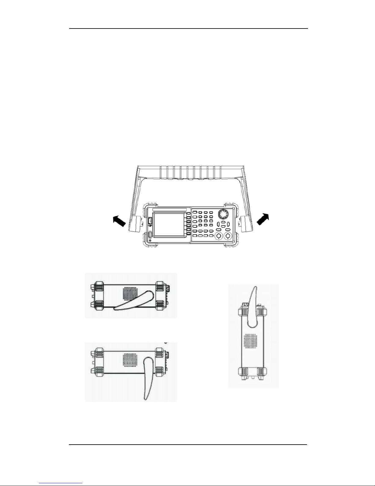
Handle Adjustment
Users can adjust the handle to the required position by pulling
the mounting points outward and adjusting the handle position.
Handle Adjustment
Horizontal Position
Carrying Position
Quick Start 3
Fuse Type
1.25 A, 250 V
4 Quick Start
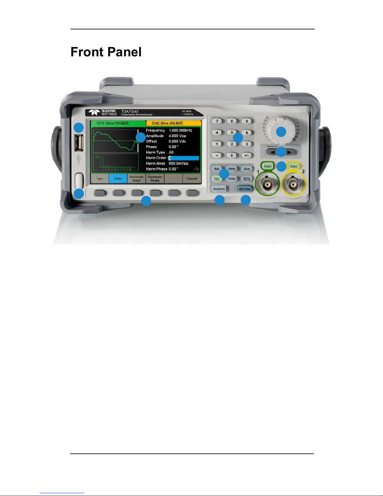
Front Panel
1
2
3 45
6
7
8
9
10
11
1 Power Button
2 USB Host Port
3 Touch Screen Display
4 Numeric Keypad
5 Adjust Knob
6 Arrow Keys
7 CH1/CH2 Control/Output Port
8 Channel Select Key
9 Function Keys
10 Waveform Selection Key
11 Menu Keys
1. Power Button
Used to turn on/off the waveform generator. When the power button is off, the
generator is under power off state.
2. USB Host Port
Used to read waveforms or status files from a USB drive or save current
instrument status to a USB drive. Firmware can be updated through the USB
port. The waveform generator supports a FAT formatted USB drive.
3. Touch Screen Display
The waveform generator has a 4.3 inch TFT color LCD display, which can
display the current function menu, parameter settings, system state, and help.
4. Numeric Keypad
Consists of numbers from 0 to 9, radix points “.” and symbol keys “+/-”, which
are used to input parameters.
Note:To enter a negative number enter a “-” symbol before the numbers.

Quick Start 5
5. Adjust Knob
●Used to increase (clockwise) or decrease (anticlockwise) the current
numerical value when setting parameters.
●Also used to change characters when inputting a file name.
●When saving or reading files, rotate the knob to choose a position to save a
file or choose a file to be read; press the knob to open a selected folder or
file.
6. Arrow Keys
●Used to adjust digits in numeric values when using the knob to set
parameters.
●Also used to position the cursor when inputting a file name.
●When saving or reading files, the arrow keys are used to choose a position
to save a file or choose a file to be read.
7. CH1 Control Port/Output Button
●The Output button on the left is used to turn on/off CH1 output.
●The nominal output impedance of the BNC connector is 50 Ω.
●When pressing Output the key backlight turns on, and the connector
outputs waveforms according to the current configuration of CH1.
CH2 Control Port/Output Button
●The Output button on the right is used to turn on/off CH2 output.
●The nominal output impedance of the BNC connector is 50 Ω.
●When pressing Output, the backlight turns on, and the connector outputs
waveforms according to the current configuration of CH2.
CAUTION:
Over voltage protection of CH1 and CH2 will take effect once any of the following
conditions is met. When over voltage protection occurs, a message will be displayed
and the output is disabled.
•The absolute value of input voltage is higher than 11 V ± 0.5 V when the amplitude of
the generator is higher than or equal to 3.2Vpp or the DC offset is higher than or equal
to |2VDC|.
•The absolute value of input voltage is higher than 4 V ± 0.5 V when the amplitude of
the generator is lower than 3.2 Vpp or the DC offset is lower than |2 VDC|.
Choose Utility → → to turn on/off the function.
!

8. Channel Select Key
Used to switch the current selected channel between CH1 and CH2.
9. Function Keys
Mod ----Modulation
Used to enable the modulation screen and allow for modulation selection. The
selection is AM, DSB-AM, FM, PM, ASK, FSK and PWM modulated signals.
• It supports “Internal” and “External” modulation sources.
• The corresponding backlight will turn on when this function is selected.
Sweep ----Sweep
Used to generate sweeping frequency signals of Sine, Square, Ramp and Arbitrary.
• It supports “Linear” and “Log” sweep profiles.
• It supports “Internal”, “External” and “Manual” trigger sources.
• The corresponding backlight will turn on when this function is selected.
Burst ----Burst
Used to generate burst signals of Sine, Square, Ramp, Noise and Arbitrary.
• It supports “NCycle”, “Gated” and “Infinite” burst modes.
• Noise can only be used to generate gated burst.
• It supports “Internal”, “External” and “Manual” trigger sources.
• The corresponding backlight will turn on when this function is selected.
Parameter ----Parameter Setting
Used to switch directly to the parameter setting interface.
• The corresponding backlight will turn on when this function is selected.
Utility ----Utility Functions and System Settings
Used to set system parameters and check version information.
• Press this key and then press the help key to obtain built-in help information
about the product.
• The corresponding backlight will turn on when this function is selected.
6 Quick Start

Quick Start 7
Store/Recall ----Store and Recall
Used to store/recall the instrument’s setup or arbitrary waveform data edited by
users.
• Can be used to perform general file operations.
• In addition to the built-in nonvolatile memory (C disk), an external USB drive (D
disk) can be used to store data.
• The corresponding backlight will turn on when this function is selected.
10.Waveform Selection Key
Waveforms ---- Sine
Provides sine wave output which ranges from 1 μHz to 40 MHz, 80 MHz or 120
MHz, depending on the model.
•The Waveforms backlight will turn on when this function is selected.
• The sine wave “Frequency/Period”, “Amplitude/High level”, “Offset/Low level” and
“Phase” can be adjusted.
Waveforms ---- Square
Provides square wave output which ranges from 1 μHz to 25 MHz.
• The Waveforms backlight will turn on when this function is selected.
• The square wave “Frequency/Period”, “Amplitude/High level”, “Offset/Low level”,
“Phase” and “Duty” can be adjusted.
Waveforms ---- Ramp
Provides ramp waveform output which ranges from 1 μHz to 1 MHz.
• The Waveforms backlight will turn on when this function is selected.
• The ramp waveform “Frequency/Period”, “Amplitude/High level”, “Offset/Low
level”, “Phase” and “Symmetry” can be adjusted.
Waveforms ---- Pulse
Provides pulse waveform output which ranges from 1 μHz to 25 MHz.
• The Waveforms backlight will turn on when this function is selected.
• The pulse waveform “Frequency/Period”, “Amplitude/High level”, “Offset/Low level”,
“Pulse width/Duty”, “Rise/Fall” and “Delay” can be adjusted.

Waveforms ---- Noise
Provides White Gauss Noise output with a bandwidth of the waveform generator
model.
• The Waveforms backlight will turn on when this function is selected.
• “Stdev” and “”Mean” of the noise signal can be adjusted.
Waveforms ---- Arb
Provides arbitrary waveform output which ranges from 1μHz to 20MHz.
• The Waveforms backlight will turn on when this function is selected.
• Supports two output modes: “DDS” and “TrueArb”.
• Built-in waveforms include Cardiac, Gauspuls, ExpRise and ExpFall, etc. In
addition, it can output waveforms stored on a USB drive.
• Users can edit arbitrary waveforms through PC software and download them to
the instrument.
• Arbitrary waveforms can be adjusted for “Frequency/Period”, “Amplitude/High
level”, “Offset/Low level” and “Phase”.
11. Menu Keys
These keys correspond to the menu displayed above them on the display. Press any
button to activate the corresponding menu.
8 Quick Start
This manual suits for next models
2
Table of contents
Other Teledyne Inverter manuals


