Telefire TSA-1000 User manual

Control Panels
TSA-1000
Conventional
Multi-Zone
Fire Alarm and Extinguishing
Control Panel
Technical Manual
T
ELEFIRE
F
IRE
&
G
AS
D
ETECTORS
L
TD
PO Box 7036
Petach Tikva 49250
Israel
Tel: 972 3 970 0400
Fax: 972 3 921 1816
eMail: marketing@telefire.co.il
Web: www.telefire.co.il
TSA
TSATSA
TSA-
--
-1000
10001000
1000En
EnEn
En112
112112
112.pdf
.pdf.pdf
.pdf
Revision 1.12
April 2012

The information contained in this document is proprietary and is subject to all relevant copyright, patent and
other laws protecting intellectual property, as well as any specific agreement protecting TELEFIRE FIRE AND
GAS DETECTORS rights in the aforesaid information. Neither this document nor the information contained
herein may be published, reproduced or disclosed to third parties, in whole or in part, without the express,
prior, written permission of TELEFIRE FIRE AND GAS DETECTORS. In addition, any use of this document
or the information contained herein for any purposes other than those for which it was disclosed is strictly
forbidden.
TELEFIRE FIRE AND GAS DETECTORS reserves the right, without prior notice or liability, to make changes
in equipment design or specifications.
Information supplied by TELEFIRE FIRE AND GAS DETECTORS is believed to be accurate and reliable.
However, no responsibility is assumed by TELEFIRE FIRE AND GAS DETECTORS for the use thereof nor for
the rights of third parties, which may be effected in any way by the use thereof.
Any representation(s) in this document concerning performance of TELEFIRE FIRE AND GAS DETECTORS
TSA-1000(s) are for informational purposes only and are not warranties of future performance either express
or implied. TELEFIRE FIRE AND GAS DETECTORS standard limited warranty, stated in its sales contract or
order confirmation form, is the only warranty offered by TELEFIRE FIRE AND GAS DETECTORS in relation
thereto.
This document may contain flaws, omissions or typesetting errors; no warranty is granted nor liability assumed
in relation thereto unless specifically undertaken in TELEFIRE FIRE AND GAS DETECTORS sales contract
or order confirmation. Information contained herein is periodically updated and changes will be incorporated
into subsequent editions. If you have encountered an error, please notify TELEFIRE FIRE AND GAS
DETECTORS. All specifications are subject to change without prior notice.
LEGAL NOTICE
i
Note
Fire alarm systems are composed and assembled of different devices and
subsystems, such as control panels, annunciators, smoke detectors, heat
detectors, manual call points, extinguishing activation devices, and
annunciating devices intended to alert to fire / smoke.
Using this system does not ensure protection from or prevention of fire and/or
smoke damages, but proper use of the system may reduce fire and smoke
damages.
Proper system configuration design, including all of its components
and infrastructure, as well as proper installation according to the
manufacturers' instructions and the applicable standards – are a
conditioned precedent for the proper and efficient function of the
system.
The designer and installer should have the appropriate skills and
qualifications for performing said installation and all damages or losses
resulting from improper design and/or installation lie with the designer and/or
installer alone.
All loss or damage caused by improper action shall lie with the
originator of said improper action.
The manufacturer shall not be liable for any fire and/or fire damages caused
by fire in location where fire systems are installed and or results of direct or
indirect fire damage that may be caused to any persons and/or property
and/or third parties as a result of using the TSA-1000 and/or resulting from its
inaction.
TSA-1000
© 2008 –2012 Telefire Fire & Gas Detectors Ltd Revision 1.12 האיגש!אצמנ אל הינפהה רוקמ .
— I —
Record of Changes
No. Date Revision Details Author
1 25.01.2012 1.12 Update Introduction, Para 2.2 (UL),
UPDATE SYMBOLIC DIAGRAM, Update note about
reading and UNDERSTANDING this document Move
Number of adapters and extinguishant quantities to appear
after "Extinguishing Adapters"
Replace Fig. 1 with original dwg. from Ylan UPDATE
INSTRUCTIONS FOR IMMEDIATE ACTION
I. Reshef
i
Note
The terms Control Panel" as used in NFPA 72 guideline and UL 864 standard
and Control and Indicating Equipment (CIE) as used in EN 54 standards are
used interchangeably throughout this manual.
i
Note
The terms “Trouble” as used in NFPA 72 guideline and UL 864 standard and
“Fault” as used in EN 54 standards are used interchangeably throughout this
manual
i
Note
All maintenance and repair work performed on the TSA-200 shall be
performed by qualified and authorized personnel ONLY
i
Note
Do not install, operate, or maintain this product before fully reading and
thoroughly understanding this manual.

TSA-1000
© 2008 –2012 Telefire Fire & Gas Detectors Ltd Revision 1.12 האיגש!אצמנ אל הינפהה רוקמ .
— II —
Table of Contents
1INTRODUCTION ............................................................................................1
2FUNCTIONS AND OPTIONS.........................................................................3
2.1
EN 54-2
O
PTIONS WITH
R
EQUIREMENTS
......................................................... 3
2.2
UL 864 ......................................................................................................... 3
3IMPORTANT NOTES .....................................................................................4
3.1
M
ANUAL
T
RIGGERING
..................................................................................... 4
3.2
M
ANUAL
T
RIGGERING
D
EVICES
....................................................................... 4
3.3
D
EPENDENCY ON
M
ORE
T
HAN
O
NE
A
LARM
S
IGNAL
.......................................... 4
3.4
T
WO
Z
ONES
C
OINCIDENCE
............................................................................. 5
3.5
N
OTE
R
EGARDING
D
EFAULT
C
ONFIGURATION
.................................................. 6
3.6
M
AXIMUM
N
UMBER OF
D
ETECTORS
................................................................. 6
3.7
S
UITABILITY OF USE IN VARIOUS ENVIRONMENTS
.............................................. 6
3.8
L
IMITING THE
C
ONSEQUENCES OF
F
AULTS
....................................................... 6
4TERMS, DEFINITIONS AND ABBREVIATIONS ...........................................8
4.1
A
BBREVIATIONS
: ............................................................................................ 8
4.2
T
ERMS AND
D
EFINITIONS
................................................................................ 8
5SAFETY .........................................................................................................9
5.1
G
ROUNDING AND
M
AINS
S
UPPLY
C
ONNECTION
................................................ 9
5.2
B
ATTERIES
H
ANDLING AND
S
AFETY
............................................................... 10
6ACCESS LEVELS........................................................................................11
7TECHNICAL SPECIFICATIONS..................................................................12
7.1
M
AIN
E
LEMENTS
,
B
ASIC
U
NIT
....................................................................... 12
7.2
E
XPANSION
M
ODULES
.................................................................................. 12
7.3
I/O
F
UNCTIONS OF THE
D
IFFERENT
E
XPANSION
B
OARDS
/M
ODULES
................ 12
7.4
R
ELAYS
....................................................................................................... 12
7.5
TSA-1000C
C
OMMUNICATION
E
XPANSION MODULE
....................................... 13
7.6
T
ABLE OF
T
ECHNICAL
S
PECIFICATIONS
,
TSA-1000 ........................................ 14
7.7
D
EFAULT
P
ORTS
A
LLOCATION AND
C
ONFIGURATION
...................................... 21
8TSA-1000 CONTROL PANEL ASSEMBLY.................................................22
8.1
P
OWER
S
UPPLY
,
C
HARGER AND
B
ATTERIES
.................................................. 22
8.2
M
AIN
B
OARD
................................................................................................ 23
8.3
E
XPANSION
M
ODULES
.................................................................................. 23
8.4
F
RONT
D
OOR
............................................................................................... 24

TSA-1000
© 2008 –2012 Telefire Fire & Gas Detectors Ltd Revision 1.12 האיגש!אצמנ אל הינפהה רוקמ .
— III —
9USER INTERFACE-DISPLAY AND KEYBOARD .......................................26
9.1
G
ENERAL
D
ISPLAY
A
REA
.............................................................................. 26
9.2
D
IGITAL
D
ISPLAY AND
D
IGITAL
D
ISPLAY
I
NDICATORS
...................................... 30
9.3
Z
ONE
I
NDICATORS
........................................................................................ 31
9.4
K
EYBOARD
.................................................................................................. 31
10 WORK STATES ...........................................................................................33
10.1
N
ORMAL
S
TATE
........................................................................................... 33
10.2
A
LARM
S
TATE
.............................................................................................. 33
10.3
F
AULT
S
TATE
............................................................................................... 34
10.4
S
UPERVISORY
S
TATE
................................................................................... 34
10.5
D
ISABLEMENT
S
TATE
................................................................................... 35
10.6
T
EST
S
TATE
................................................................................................. 35
11 INSTALLATION ...........................................................................................36
11.1
P
RE
-I
NSTALLATION
P
LANNING
....................................................................... 36
11.2
M
OUNTING
................................................................................................... 37
11.3
W
IRING
....................................................................................................... 38
11.4
I
NSTALLING
D
ETECTORS
,
I
NPUT AND
O
UTPUT
D
EVICES
,
AND
O
THER
D
EVICES
. 42
11.5
C
ONNECTING THE MAINS
,
BATTERIES AND THE GROUND WIRE
. ........................ 44
11.6
P
OST
-I
NSTALLATION
..................................................................................... 45
11.7
C
ONNECTING A
TDM-500
I
D
IALER
................................................................ 46
12 EXTINGUISHING .........................................................................................48
12.1
A
UTOMATIC
E
XTINGUISHING
......................................................................... 48
12.2
M
ANUAL
E
XTINGUISHING
.............................................................................. 48
12.3
E
XTINGUISHING
O
UTPUT
.............................................................................. 48
12.4
E
MERGENCY
H
OLD AND
E
MERGENCY
A
BORT
................................................. 48
12.5
P
OST
-A
CTIVATION
I
NDICATION
...................................................................... 48
12.6
A
CTIONS TO
P
ERFORM
A
FTER
E
XTINGUISHING
A
CTIVATION
............................ 49
12.7
R
EESTABLISHING THE
Q
UIESCENT
C
ONDITION AFTER
E
XTINGUISHING
............. 49
13 CONNECTING EXTINGUISHING EQUIPMENT ..........................................50
13.1
E
XTINGUISHING
A
DAPTERS
........................................................................... 50
13.2
N
UMBER OF
E
XTINGUISHING
A
DAPTERS
........................................................ 50
13.3
E
XTINGUISHANT
Q
UANTITIES
........................................................................ 51
13.4
F
IKE
FIRERASER ....................................................................................... 51
13.5
F
IKE
GCA.................................................................................................... 52
13.6
G
REEN
EX
A
EROSOL
C
ONTAINERS
................................................................ 52
13.7
F
IRE
P
RO
A
EROSOL
C
ONTAINERS
.................................................................. 53

TSA-1000
© 2008 –2012 Telefire Fire & Gas Detectors Ltd Revision 1.12 האיגש!אצמנ אל הינפהה רוקמ .
— IV —
13.8
A
T
YPICAL
A
PPLICATION
–
E
XTINGUISHING AND
E
LECTRICITY
D
ISCONNECT
..... 53
14 CONTROL PANEL PROGRAMMING..........................................................55
14.1
M
ENU
S
TRUCTURE
....................................................................................... 55
14.2
E
NTERING
P
ROGRAMMING
M
ODE
.................................................................. 55
14.3
K
EY
F
UNCTIONS DURING
P
ROGRAMMING
....................................................... 55
14.4
D
ISPLAY
D
URING
P
ROGRAMMING
.................................................................. 56
14.5
P
ROGRAMMING
S
EQUENCE
........................................................................... 57
14.6
D
IALER
P
ROGRAMMING
................................................................................ 58
14.7
H
ORN
O
UTPUT
P
ROGRAMMING
..................................................................... 58
14.8
E
XPANSION
C
ARD
P
ROGRAMMING
................................................................ 58
14.9
R
EMOTE
A
NNUNCIATOR
P
ROGRAMMING
........................................................ 59
14.10
N
ETWORK
P
ROGRAMMING
............................................................................ 59
14.11
R
ELAY
P
ROGRAMMING
................................................................................. 59
14.12
Z
ONE
P
ROGRAMMING
................................................................................... 61
14.13
O
UTPUT
P
ROGRAMMING
............................................................................... 62
14.14
S
AVING
D
ATA AND
E
XITING
P
ROGRAMMING
M
ODE
......................................... 64
15 OPERATION AND MAINTENANCE ............................................................65
15.1
E
VACUATION
(EVC) ..................................................................................... 65
15.2
O
N
/
O
FF
Z
ONE OR
O
UTPUT
(OFF) ............................................................... 65
15.3
F
IELD
T
EST
(
FT
) ........................................................................................... 65
15.4
E
VENT
L
OG
(LOG)....................................................................................... 66
15.5
A
LARM
C
OUNTER
(ALC) ............................................................................... 66
15.6
C
HANGING
P
ASSWORD
(PAS)....................................................................... 66
15.7
S
ETTING
T
IME AND
D
ATE
(
T
+
D
)..................................................................... 66
15.8
L
AMP
T
EST
(
LT
)............................................................................................ 67
15.9
A
DDITIONAL
I
NFORMATION
(
IN
F).................................................................... 67
15.10
R
ESTORING
D
EFAULT
C
ONFIGURATION
(
D
EF)................................................ 67
16 TROUBLESHOOTING .................................................................................68
16.1
M
AINTENANCE
A
LERT
................................................................................... 68
16.2
S
YSTEM
S
TATES
.......................................................................................... 68
16.3
S
YSTEM
F
AULTS
.......................................................................................... 68
16.4
P
ROGRAMMING
F
AULTS
................................................................................ 70
17 COMMISSIONING........................................................................................72
18 MAINTENANCE ...........................................................................................74
19 ROUTINE TESTING.....................................................................................75

TSA-1000
© 2008 –2012 Telefire Fire & Gas Detectors Ltd Revision 1.12 האיגש!אצמנ אל הינפהה רוקמ .
— V —
19.1
W
EEKLY
I
NSPECTION
–
T
O
B
E
P
ERFORMED BY
S
ITE
P
ERSONNEL
.................... 75
20 CERTIFICATION..........................................................................................76

TSA-1000
© 2008 –2012 Telefire Fire & Gas Detectors Ltd Revision 1.12 האיגש!אצמנ אל הינפהה רוקמ .
— VI —
Tables of Figures
Figure 1
TSA-1000 typical system 7
Figure 2
Module location 22
Figure 3
Display and Keyboard 25
Figure 4
General Display Area 26
Figure 5
Digital Display and Digital Display Indicators 31
Figure 6
Zone Indicators 31
Figure 7
Keyboard 31
Figure 8
Chassis Mounting Holes 38
Figure 9
Routing High- and Low Voltage cables in the TSA-1000 Chassis 40
Figure 10 RM-1000 connection 41
Figure 11 Connecting a network 41
Figure 12 Main Board Connectors 42
Figure 13 Expansion Module Connectors 43
Figure 14 Connecting Two Detectors and a TPB-10R Break-Glass 43
Figure 15 Connecting Programmable and General Sounders 43
Figure 16 Connecting the grounding wire to the Chassis 44
Figure 17 Connecting a TDM-500i Dialer (W/W rev C5, S/W rev 2.05.01) 46
Figure 18 Connecting a FIRERASER Cylinder for Automatic Extinguishing 51
Figure 19 Connecting a GCA-Activated Extinguishing Cylinder 52
Figure 20 Connecting a GreenEX Aerosol Extinguishing Container 52
Figure 21 Connecting FirePro Aerosol Generators 53
Figure 22
A typical application – cross-zone activation of electricity disconnect,
evacuation volume extinguishing 54
Figure 23 Programming Menu Structure 55
Figure 24
The seven-segment display and representation of digits and letters 57
Figure 25 Device selection 58
Figure 26 Display during relay programming 60
Figure 27
Programmable Relay Contacts During Normal Operations and Upon
Activation 61
Figure 28 Display during input programming 62
Figure 29 Display during output programming 63
List of Tables
Table 1
Technical Specifications 20
Table 2
TSA-1000 – number of inputs and outputs of the various configurations 24
Table 3
IDC cable selection 36
Table 4
Wiring Characteristics’ influence on System Performance 39

TSA-1000
© 2008 –2012 Telefire Fire & Gas Detectors Ltd Revision 1.12 האיגש!אצמנ אל הינפהה רוקמ .
– Page 1 of 1 –
1 Introduction
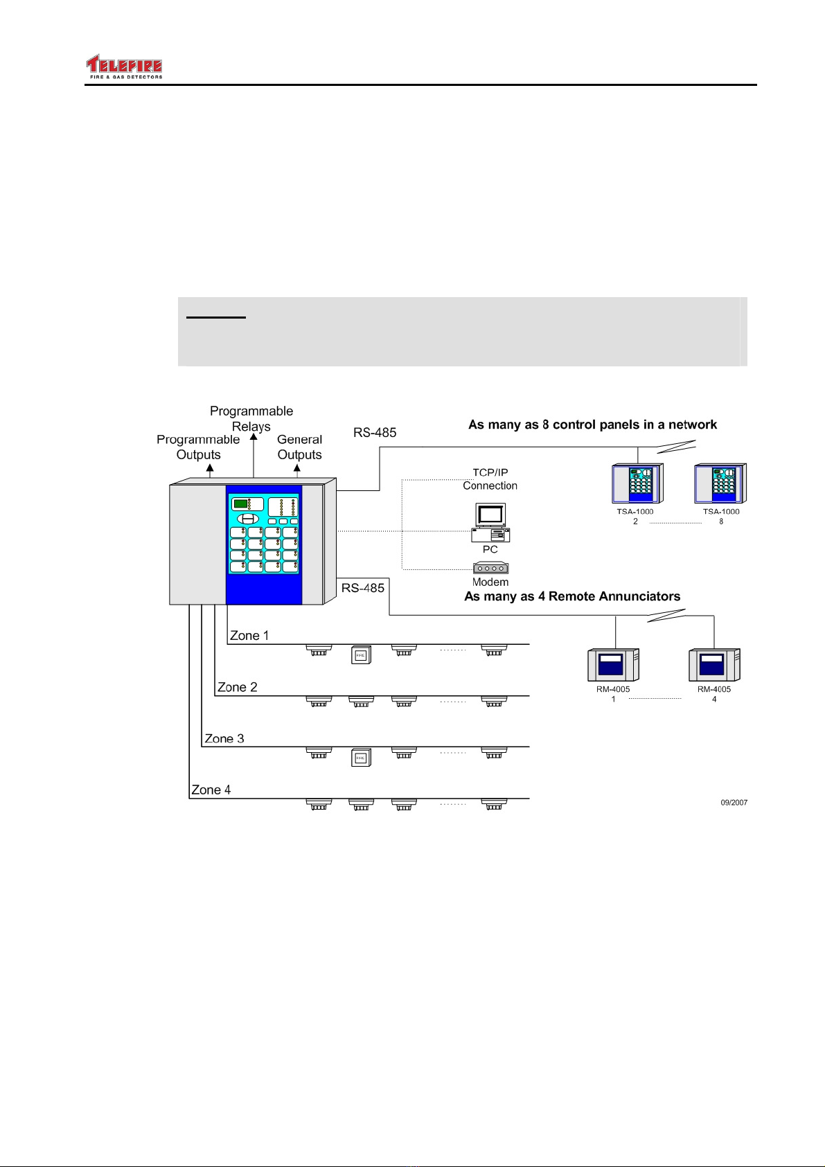
Telefire's TSA-1000 Conventional (i.e. Non Addressable) Multi-Zone Fire Alarm Control
Panel complies with numerous standards. It is certified to EN 54-2 and EN 54-4. It is
also CE marked and is certified to GOST 53325-2009 and to IS 1220. It also complies
with UL 864 edition 9.
The control panel is modular and can be extended up to 16 input zones, with options for
other expansions.
The base control panel contains four programmable zones, four programmable outputs,
a horn output, a Fire Alarm dialer output, and three programmable relays.
The control panel is modular and is expandable via various modules that include inputs,
outputs, and relays to implement complex logic functions.
Up to four remote panels can be connected via an RS-485 interface (part of the
TSA-1000C, a communication expansion card). Computer communication and remote
panels are also supported through the TSA-1000C
The TSA-1000 supervises two-wire IDC lines ("zones") and outputs that can be used to
activate sounders, automatic extinguishing devices, evacuation sounders, or other
notification equipment. Additionally, the control panel has separate outputs for activating
a main sounder, automatic dialer, and "dry" contacts (of relays) to indicate alarm, fault,
and supervisory events of the system.
All input and output lines are fully supervised. The output lines are constantly monitored
and are automatically disconnected when current draw exceeds the allowed values.
Input and output line protection is done without the use of fuses, using Telefire's unique
ACM (Advanced Current Management) that provides high resilience even during fault
events and automatic return to normal operation with problem resolution.
Any event in the system is clearly displayed in detail and allows quick and easy
troubleshooting for the user, operator, and service technician.
All programming and configuration can be done easily through the panel's keyboard or
via dedicated software.
As the system is computerized, it allows working in various modes that can be easily
reconfigured in the field without special tools, yet allowing access only to authorized
personnel.
The TSA-1000 can be programmed as a fire alarm panel, fire alarm and extinguishing
panel that includes cross-zoning, extinguishing activation delay, or a combination of the
two. Additionally, it is possible to delay alarm from specific zones and cross zones to
neutralize false alarms from difficult locations such as areas with forklift activities, etc.
The system's inputs, outputs, and relays are fully configurable including complex logic
operations involving multiple outputs and multiple inputs.
The TSA-1000 allows output activation in four ways: general, specific zone, cross-zones
of several zones, and one of several zones, through unique matrix logic (AAM –
Advance Activation Matrix).
The system includes a maintenance alert for detectors (dependant on using Telefire
detectors), a function that required, until now, analog addressable panels.
Battery charging is fully supervised – including charging voltage, charging current, and
monitoring of the battery's ability to supply the required current.
A special work mode (Field Test) allows detector testing using only one technician,
whilst differentiating between activations that are done for testing purposes and real
alarms.

TSA-1000
© 2008 –2012 Telefire Fire & Gas Detectors Ltd Revision 1.12 האיגש!אצמנ אל הינפהה רוקמ .
– Page 2 of 2 –
The system supports an automatic alarm verification feature, to decrease the occurrence
of false alarms, and a time and date clock for logging system events. System log can be
viewed via a PC or printed for system investigation purposes.
The TSA-1000 can be connected to form a network of control panels.

TSA-1000
© 2008 –2012 Telefire Fire & Gas Detectors Ltd Revision 1.12 האיגש!אצמנ אל הינפהה רוקמ .
– Page 3 of 3 –
2 Functions and Options
2.1 EN 54-2 Options with Requirements
The TSA-1000 conforms fully to European standards BS EN 54-2:1998 and
BS EN 54-4:1998 and the following optional features:
•Output to fire alarm devices – EN 54-2 Section 7.8 option with requirements
•Output to fire alarm routing equipment – EN 54-2 Section 7.9 option with
requirements
•Output to fire protection equipment – EN 54-2 Section 7.10 option with requirements
•Coincidence detection– EN 54-2 Section 7.12 option with requirements
(Provided as a two zones coincidence and as a single/Dual zone AVF- Alarm
Verification Function)
•Alarm Counter – EN 54-2 Section 7.13 option with requirements
•Total loss of power supply – EN 54-2 Section 8.4 option with requirements
•Output to fault warning routing equipment – EN 54-2 Section 8.9 option with
requirements
•Test condition – EN 54-2 Section 10 option with requirements
2.2 UL 864
The TSA-1000 complies with UL 864 edition 9

TSA-1000
© 2008 –2012 Telefire Fire & Gas Detectors Ltd Revision 1.12 האיגש!אצמנ אל הינפהה רוקמ .
– Page 4 of 4 –
3 Important Notes
3.1 Manual Triggering
Any of the inputs can be configured as a manual (extinguishing) release input, or as a
Manual Call Point (i.e. Manual Alarm Input). Asserting the Manual release (i.e. pressing
the PB) causes immediate extinguishing.
i
Note
If a remote (non panel mounted) extinguishing manual triggering device is
used, then USE ONLY an approved and certified Extinguishing Triggering
Device of the correct color as per EN 12094-3.
i
Note
If a remote (non panel mounted) Manual Call Point is used, then USE ONLY
an approved and certified Device of the correct color as per EN 12094-3 and
EN 54-2.
If two zones coincidence is not required by your national regulations, you may change
the configuration so the ECD activates on any single zone which is configured as a
member of the Extinguishing Decision Group.
i
Note
Trigger on coincidence of more than two independent sources does not
comply with the 12094-1 standard.
3.2 Manual Triggering Devices
i
Note
When an extinguishing manual triggering device is used, then USE ONLY an
approved and certified Extinguishing Triggering Device of the correct color as
per EN 12094-3.
3.3 Dependency on More Than One Alarm Signal
The TSA-1000 supports Coincidence detection– per EN 54-2 Section 7.12 option with
requirements
(Provided as a two zones coincidence and as a single/Dual zone AVF- Alarm Verification
Function)
The "Dependency on more than one alarm signal" function, also termed (By UL) "Alarm
Verification Function" (AVF), as detailed in EN-54-2, paragraph 7.12.
The alarm Delay and Confirmation (verification) feature allows the control panel to ignore
false, short and transient alarm events, which may cause a nuisance and unnecessary
extinguishing.
This feature is based on an Alarm Delay Period, and an Alarm Confirmation Period.

TSA-1000
© 2008 –2012 Telefire Fire & Gas Detectors Ltd Revision 1.12 האיגש!אצמנ אל הינפהה רוקמ .
– Page 5 of 5 –
The alarm delay can be programmed, PER ZONE, to OFF (No Delay, No Alarm
Verification) or to ON. Each detection zone can be programmed independently.
If the zone Alarm Delay is programmed ON, there is a 30 seconds alarm Delay. During
the delay period alarms are ignored. This is followed by a 180 seconds confirmation
period.
When a zone programmed for alarm verification is first triggered, the control panel resets
the zone in alarm, waits for 30 seconds (if Delay is ON) and enters a 180 seconds (3
minutes) confirmation period. During the 30 seconds delay period, alarms are ignored.
During the 180 seconds confirmation period, the control panel enters the alarm state
immediately if a trigger from the same zone or from another zone is received, even if the
other zone is programmed for alarm delay and confirmation).
If, during the alarm confirmation period, no alarm is received, the ECD reestablishes the
quiescent condition.
Each detectors zone can be independently programmed for Alarm Delay and
Confirmation, (Alarm Verification).
The dependencies supported, as per EN 54-2, paragraph 7.12 are type A or type B,
depending on the configuration of the TSA-1000.
3.4 Two Zones Coincidence
The detailed explanation of the operation of the ECD is provided in Work States, page
33, and in Operation and Maintenance, page 65.
Coincidence detection– EN 54-2 Section 7.12 option with requirements
is implemented in the TSA-1000 as a two zones coincidence and as a single/Dual zone
AVF- Alarm Verification Function).
AVF was explained above. "Two Zones Coincidence" is explained below
When the ECD is configured for two zones coincidence, then a trigger from one of the
zones which are members of the extinguishing decision group will change the state of
the ECD to "Fire Alarm", and to the "Preactivated State". Trigger from a second zone,
which is a member of the extinguishing decision group, will cause the CIE to enter the
"Activated" state. If a Non-Zero Delay is programmed, the CIE will enter the "Pre
Discharge Warning Time", (extinguishing delay). If Delay is zero, or the warning time
(delay) expires, the extinguisher is triggered.
i
Note
If zones, which are not members of the extinguishing decision group, are
triggered, the ECD changes state to "Fire Alarm", BUT DOES NOT start the
extinguishing process, and the extinguisher is NOT ACTIVATED even if two
such zones are triggered.

TSA-1000
© 2008 –2012 Telefire Fire & Gas Detectors Ltd Revision 1.12 האיגש!אצמנ אל הינפהה רוקמ .
– Page 6 of 6 –
3.5 Note Regarding Default Configuration
i
Note
By default, the TSA-1000 is programmed for all input zones are detectors
zones and all outputs are general outputs.
To modify these and additional settings, the TSA-1000 must be programmed
accordingly.
3.6 Maximum Number of Detectors
EN 54-2 specifies a limit of 32 detectors per zone, which is the limit of each zone of the
TSA-1000; hence the TSA-1000 max number of detectors is dependant on the
configuration, and the number of zones.
3.7 Suitability of use in various environments
See Mounting, page 37
3.7.1 Environmental Limits and Protection Level
The TSA-1000 environmental limits are specified in EN-54-02:1998 para. 12.
The TSA-1000 is specified for -5°C to +40°C, RH max 95% temperature range, and
IP30 protection level.
i
Note
See Routing cables into the ECD and maintaining the protection level,
page 38, for information about maintaining the protection level.
i
Note
Do not operate the ECD outside the specified limits.
3.7.2 Suitable Environment
The TSA-1000 environmental limits are stated above. It is to be installed in an indoors
location, well ventilated location, protected from the elements.
Avoid locating the CP in direct sunlight or near sources of heat.
It is recommended to install the CP in an electrically quiet location (i.e. away from high
power cables, motors, etc).
3.8 Limiting the Consequences of Faults
See POWER SUPPLY, CHARGER AND BATTERIES, page 22, for explanation of
PS/Charger limiting/protection devices.
The Main Board, which contains the charging circuitry and the battery protective
resettable PTC, also has a common electronic limiter for most output ports (It does not
protect the contacts of relays!), which are monitored by the CPU
If there is an overload on an output (or outputs), the common limiter shuts off, the buzzer
sounds and the visual fault indication and the Fault relay are switches ON. The CPU
switches OFF all the controlled outputs. It then switches ON the separate outputs in
TSA-1000
© 2008 –2012 Telefire Fire & Gas Detectors Ltd Revision 1.12 האיגש!אצמנ אל הינפהה רוקמ .
– Page 7 of 7 –
sequence, until the faulty output is isolated. All appropriate "good" outputs are then
switched back ON, except for the faulty outputs.
The controlled outputs (i.e. not relays' contacts or OC outputs) are continuously
monitored.
Recovery from faults is detected by the CPU and all relevant recovered outputs are
reactivated, if necessary.
Open Collector outputs are current limited by design, by series connected high value
resistors.
i
Note
Relays' contacts are not monitored, supervised or protected.
Connect external protective circuitry to the relays' contacts circuitry.
Figure 1 TSA-1000 typical system

TSA-1000
© 2008 –2012 Telefire Fire & Gas Detectors Ltd Revision 1.12 האיגש!אצמנ אל הינפהה רוקמ .
– Page 8 of 8 –
4 Terms, Definitions and Abbreviations
4.1 Abbreviations:
Abbreviation
Meaning Remarks
CP Control Panel
ECD Electrical Automatic Control and Delay Device
TB Terminal Block
MCP Manual Call Point
PB Push Button
PC Personal Computer
PS Power Supply
PW Password
M Minute
# (Number)
FWRE Fault Warning Routing Equipment Fault Dialer
FARE Fire alarm Routing Equipment Alarm Dialer
AC Alternating Current
AH Ampere Hours
RH Relative Humidity
PTC Positive Temperature Coefficient (FUSE)
4.2 Terms and Definitions
TERM MEANING
Event A change which is detectable by the ECD and causes a response

TSA-1000
© 2008 –2012 Telefire Fire & Gas Detectors Ltd Revision 1.12 האיגש!אצמנ אל הינפהה רוקמ .
– Page 9 of 9 –
5 Safety
i
Note
Do not install commission, operate, or maintain this product before fully
reading and thoroughly understanding this manual.
i
Note
Whenever possible, disconnect all power sources (Line AND Battery) from
the product before performing any work on the ECD.
5.1 Grounding and Mains Supply Connection
i
Note
All installation, maintenance work and connecting/Disconnecting of the ECD
to power sources shall be performed according to applicable international,
national, regional and local codes and regulations, and the specific
instructions by the manufacturer.
i
Note
All maintenance work should only be performed by trained, qualified and
certified personnel only.
Personnel that work on this equipment must fully read and comprehend this
manual.
i
Note
Connection/Disconnection of the control panel to the mains should be
performed by QUALIFIED AND AUTHORIZED personnel ONLY
i
Note
Disconnect all mains power wires (Line AND Neutral) to the circuit to which
you intent to connect the control panel, before actually connecting the mains
input power cable to the ECD.
Verify that the ECD enclosure is properly grounded before applying power

TSA-1000
© 2008 –2012 Telefire Fire & Gas Detectors Ltd Revision 1.12 האיגש!אצמנ אל הינפהה רוקמ .
– Page 10 of 10 –
5.2 Batteries Handling and Safety
i
Note
Batteries require special care and safety precautions.
Refer to the batteries’ manufacturer literature for full information.
The following information supplements and highlights manufacturer’s information.
WHEN HANDLING BATTERIES, OBSERVE THE MANUFACTURER’S
RECOMMENDATIONS REGARDING CLOTHING AND PROTECTIVE GEAR
Use two 12V 5 AH sealed Lead Acid batteries, such as Yuasa NP5-12 or equivalent,
connected in series.
Use the supplied wires to connect to the batteries, and to connect two batteries in series.
Since the batteries used are maintenance free, and the ECD automatically controls the
battery charging, discharge and test, no SPECIAL maintenance is required.
OBSERVE THE FOLLOWING:
Connect the battery to the ECD main board battery terminal block using the supplied
wires. Observe polarity.
Keep the batteries clean and dry
Keep the area well ventilated
Smoking, fire or sparks ARE NOT ALLOWED near batteries.
When working on batteries, DISCONNECT THE BATTERIES AND ALL OTHER
POWER SOURCES
i
Note
If batteries show any signs of swelling, rupture, fluid leakage, emission of
gases or fluids, heating or discoloration, or accumulation of corrosion
products near the terminals, OR YOU HEAR A HISSING SOUND, disconnect
the batteries and replace with a new pair of the appropriate type.
Follow the manufacturer’s instructions for cleaning the batteries and the enclosure, if
necessary
Dispose of batteries properly
Do not short-circuit, puncture, crush, or dispose of batteries in fire.
Do not connect batteries to makeshift chargers or power supply.
Do not expose the batteries or its terminals to mechanical stress
Handling of materials that leak from the batteries should be done by qualified personnel
using the appropriate protective gear, materials, and procedures.
If the ECD indicates a battery fault, check the wiring.
If necessary, replace the batteries

TSA-1000
© 2008 –2012 Telefire Fire & Gas Detectors Ltd Revision 1.12 האיגש!אצמנ אל הינפהה רוקמ .
– Page 11 of 11 –
6 Access Levels
The control panel provides protection from unauthorized access of certain functions by
various access levels.
The TSA-1000 includes electronic and mechanical mechanisms that enact 4 access
levels, as per EN 54-02 Annex A:
•Access level 1 – not limited, immediate access by operator
•Access level 2 (operator) – protected by an operator password. Provides all of
access level 1 functions and allows access to additional functions that are
performed on a regular basis by the system’s operator.
i
Note
To avoid multiple PW key punching, there is a 3 minutes period after the
operator's PW has been entered, when the PW remains valid and effective,
which enables the operator to perform several tasks continuously without
entering the PW separately for each action.
(Since. In the password delay, the reentering of level 2 PW is not required,
level 2 access appears to be level 1 access, and level 3 appears to be level 2
access)
Access level 3 (programmer & installer) – protected by a programmer
password (different from the operator's password!)or a mechanical key.
Provides all of access to level 1 and 2 functions and allows access to
additional functions such as programming, and access for functions
performed during installation.
i
Note
Access levels 2 and 3 have different passwords. This is not correlated to the
number of times the password has to be keyed in to access a certain menu.
Some sub-menus which are accessible at level 3, require that the level 3
(programmer) password be entered in a single menu, while others (for
additional safety) require the level 3 password to be entered in to different
menus
•Access level 4 (manufacturer) – Only accessible using a dedicated PC SW tool or a
mechanical key.
The mechanically controlled access elements are detailed below.
The ECD enclosure has a door/front-panel with a mechanical lock. A detachable key is
required to open the lock, which requires a positive and deliberate action and prevents
accidental and non authorized access. Hence the access level to the batteries and AC
power lines and the field wiring connections is 3/4.
Two switches are located on the front panel. A Manual &Automatic/Manual Only key-
switch and a Manual Activation Push Button switch.

TSA-1000
© 2008 –2012 Telefire Fire & Gas Detectors Ltd Revision 1.12 האיגש!אצמנ אל הינפהה רוקמ .
– Page 12 of 12 –
7 Technical Specifications
7.1 Main Elements, Basic Unit
The TSA-1000 comprises the following major elements:
•A metal enclosure with a hinged and mechanically lockable door. The door also
serves as the front panel
•PS40W Power Supply / Charger
•TSA-1000 Main Board (1 change polarity output, 5 level activation outputs, 4 inputs,
3 relays)
•TSA-1000D Display board
•Flat Cable for connecting the Main Board to the Display board
•Two 12V 5AH batteries (Connected in series).
•Link wire for connecting the two batteries in series
•Two (single) wires for connecting the batteries to the PS "BATTERY" TBs.
•Flat Cable for connecting the PS to the main Board
•Two 4 wire cables, for connecting the MB to the TSA-1000E8 card.
•Clamp On ferrite on AC input cable
•Clamp On ferrite on flat cable from MB to the display board.
7.2 Expansion Modules
The TSA-1000 basic unit functionality can be extended using the following expansion
boards/modules;
•TSA-1000E4 expansion board (4 inputs)
•TSA-1000E8 expansion board (8 inputs)
•TSA-1000EM083 expansion board (8 Open Collector outputs, 3 relays)
Prerequisite: TSA-1000E4 or TSA-1000E8
•TSA-1000EM422 expansion board (4 inputs, 2 programmable outputs, 3
programmable relays)
Prerequisite: TSA-1000E4 or TSA-1000E8
•TSA-1000C Communication module
7.3 I/O Functions of the Different Expansion Boards/Modules
The MB inputs and the expansion modules inputs are of the same design and have
identical electrical characteristics. So are the Relays, Level Activation outputs, Open
Collector outputs, etc.
The alarm dialer output is a level activation output with educed current capability (0.6A
instead of 0.8A).
7.4 Relays
Relays' contacts are not monitored, supervised or protected.
Connect external protective circuitry to the relays' contacts.
Relays are intended for same room connection only.
Table of contents
Other Telefire Control Panel manuals


