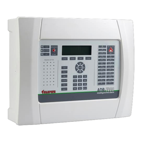
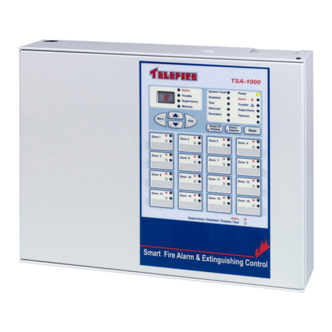
Telefire TSA-200 User manual

Control Panels
TSA-200 / TSA-200XT
and
TSA-240 / TSA-240XT
Conventional
Two-and Four-Zone
Fire Alarm Control Panel
Technical Manual
T
ELEFIRE
F
IRE
&
G
AS
D
ETECTORS
L
TD
PO Box 7036
Petach Tikva 49250
Israel
Tel: 972 3 970 0400
Fax: 972 3 921 1816
eMail: info@telefire.co.il
Web: www.telefire.co.il
TSA
TSATSA
TSA-
--
-200
200200
200En
EnEn
En106
106106
106.pdf
.pdf.pdf
.pdf
Revision 1.06
July 2014

COPYRIGHT NOTICE
The information contained in this document is proprietary and is subject to all relevant copyright, patent and other laws protecting intellectual property, as well
as any specific agreement protecting TELEFIRE FIRE AND GAS DETECTORS rights in the aforesaid information. Neither this document nor the information
contained herein may be published, reproduced or disclosed to third parties, in whole or in part, without the express, prior, written permission of TELEFIRE
FIRE AND GAS DETECTORS. In addition, any use of this document or the information contained herein for any purposes other than those for which it was
disclosed is strictly forbidden.
TELEFIRE FIRE AND GAS DETECTORS reserves the right, without prior notice or liability, to make changes in equipment design or specifications.
Information supplied by TELEFIRE FIRE AND GAS DETECTORS is believed to be accurate and reliable. However, no responsibility is assumed by
TELEFIRE FIRE AND GAS DETECTORS for the use thereof nor for the rights of third parties, which may be affected in any way by the use thereof.
Any representation(s) in this document concerning performance of TELEFIRE FIRE AND GAS DETECTORS product(s) are for informational purposes only
and are not warranties of future performance either express or implied. TELEFIRE FIRE AND GAS DETECTORS standard limited warranty, stated in its
sales contract or order confirmation form, is the only warranty offered by TELEFIRE FIRE AND GAS DETECTORS in relation thereto.
This document may contain flaws, omissions or typesetting errors; no warranty is granted nor liability assumed in relation thereto unless specifically
undertaken in TELEFIRE FIRE AND GAS DETECTORS sales contract or order confirmation. Information contained herein is periodically updated and
changes will be incorporated into subsequent editions. If you have encountered an error, please notify TELEFIRE FIRE AND GAS DETECTORS. All
specifications are subject to change without prior notice.
LEGAL NOTICE
i
Note
Fire alarm systems are composed and assembled of different devices and
subsystems, such as control panels, annunciators, smoke detectors, heat
detectors, manual call points, extinguishing activation devices, and
annunciating devices intended to alert to fire / smoke.
Using this system does not ensure protection from or prevention of fire and/or
smoke damages, but proper use of the system may reduce fire and smoke
damages.
Proper system configuration design, including all of its components
and infrastructure, as well as proper installation according to the
manufacturers' instructions and the applicable standards – are a
conditioned precedent for the proper and efficient function of the
system.
The designer and installer should have the appropriate skills and
qualifications for performing said installation and all damages or losses
resulting from improper design and/or installation lie with the designer and/or
installer alone.
All loss or damage caused by improper action shall lie with the
originator of said improper action.
The manufacturer shall not be liable for any fire and/or fire damages caused
by fire in location where fire systems are installed and or results of direct or
indirect fire damage that may be caused to any persons and/or property
and/or third parties as a result of using the product and/or resulting from its
inaction.

TSA-200 / TSA-200XT / TSA-240 / TSA-240XT
© 2010 – 2014 Telefire Fire & Gas Detectors Ltd Revision 1.06 July 2014
— I —
Record of Changes
No. Date Revision Details Author
1 14.04.2011 1.00 Initial Release I. Reshef
2 17.07.2011 1.01 Minor corrections-update front panel display functions.
Remove reference to EVAC sounder silencing and clarify
silencing for all devices.
Distinguish between Reset and Disablements.
Update Front Panel functionality.
Add EOL paragraph.
ADD EOL resistors in drawings. (or add note about EOL
resistors in the drawings)
Update EOL and reorder paragraphs
Update mounting
I. Reshef
3 23.08.2011 1.02 Update Table of states and the explanations following it
Update Labels
Update explanations and operations
Replace TSA-200X with TSA-200 / TSA-200XT
I. Reshef
4 03.10.2011 1.03 Relocate " Limiting the consequences of faults" and
"Suitability for use in various environment" to "Important
Notes"
Move "TSA-200/TSA-200XT Control Panel Assembly"
Before "Installation"
Add header "Wiring Considerations" after 'maintaining the
protection level
Relocate "Configuring the Control Panel" from end of
"Installation" to " Post Installation"
I. Reshef
5 17.10.2011 1.04 Move "Modules location" to "Assembly"
Add CE label
Move "Extinguishant Quantities" below "Extinguishing
Adapters and rename to "Number of adapters"
Update Default Ports Allocation and Configuration"
I. Reshef
6 24.10.2011 1.05 Eliminate line separation in tables
Update the last page, Instructions for immediate use, from
its separate source document
Perform changes per Boris remarks. Stress difference of
TSA-200XT from TSA-200X
Update default parameters (no ext. delay) and PC
programming.
Remove "Table of States".
Update phone number.
I. Reshef
7 18.03.2014 1.06 Correct minor errors
Refer to revised EM1
Updated to reflect TSA-240 / 240XT
I. Reshef

TSA-200 / TSA-200XT / TSA-240 / TSA-240XT
© 2010 – 2014 Telefire Fire & Gas Detectors Ltd Revision 1.06 July 2014
— II —
i
Note
The terms Control Panel" as used in NFPA 72 guideline and UL 864 standard
and Control and Indicating Equipment (CIE) as used in EN 54 standards are
used interchangeably throughout this manual.
i
Note
The terms “Trouble” as used in NFPA 72 guideline and UL 864 standard and
“Fault” as used in EN 54 standards are used interchangeably throughout this
manual
i
Note
All maintenance and repair work performed on the TSA-200 shall be
performed by qualified and authorized personnel ONLY
i
Note
Do not install, operate, or maintain this product before fully reading and
thoroughly understanding this manual.

TSA-200 / TSA-200XT / TSA-240 / TSA-240XT
© 2010 – 2014 Telefire Fire & Gas Detectors Ltd Revision 1.06 July 2014
— III —
Table of Contents
1
INTRODUCTION ............................................................................................1
2
FUNCTIONS AND OPTIONS.........................................................................2
2.1 EN 54-2
–
O
PTIONS WITH
R
EQUIREMENTS
...................................................... 2
2.2 UL 864 ......................................................................................................... 2
2.3 TSA-200XT
/
TSA-240XT
E
XTINGUISHING
-S
PECIFIC
F
UNCTIONS
.................... 2
2.4 A
DDITIONAL
F
UNCTIONS
................................................................................. 2
2.5 S
UPPORT
F
UNCTIONS
.................................................................................... 2
3
IMPORTANT NOTES .....................................................................................3
3.1 T
RIGGERING
R
EQUIREMENTS
.......................................................................... 3
3.2 S
INGLE
Z
ONE
A
CTIVATION
.............................................................................. 3
3.3 T
WO
Z
ONES
C
OINCIDENCE
............................................................................. 3
3.4 D
EPENDENCY ON
M
ORE
T
HAN
O
NE
A
LARM
S
IGNAL
.......................................... 3
3.5 N
OTE
R
EGARDING
D
EFAULT
C
ONFIGURATION
.................................................. 4
3.6 N
UMBER OF
D
ETECTORS
................................................................................ 4
3.7 TSA-200,
TSA-200XT
EN
C
ERTIFICATION
...................................................... 4
3.8 UL 864
COMPATIBILITY
................................................................................... 4
3.9 S
UITABILITY OF USE IN VARIOUS ENVIRONMENTS
.............................................. 5
3.10 L
IMITING THE
C
ONSEQUENCES OF
F
AULTS
....................................................... 5
4
TERMS, DEFINITIONS AND ABBREVIATIONS ...........................................7
4.1 A
BBREVIATIONS
............................................................................................. 7
4.2 T
ERMS AND
D
EFINITIONS
................................................................................ 8
4.3 F
UNCTIONAL
D
RAWING
................................................................................... 8
5
SAFETY .........................................................................................................9
5.1 G
ROUNDING AND
M
AINS
S
UPPLY
W
IRES
C
ONNECTION
..................................... 9
5.2 B
ATTERIES
H
ANDLING AND
S
AFETY
................................................................. 9
6
ACCESS LEVELS........................................................................................11
7
TECHNICAL SPECIFICATIONS..................................................................12
7.1 M
AIN
E
LEMENTS
.......................................................................................... 12
7.2 N
UMBERING OF
I
NPUTS AND
O
UTPUTS
.......................................................... 12
7.3 T
ABLE OF
T
ECHNICAL
S
PECIFICATIONS
,
TSA-200
PRODUCT FAMILY
................ 13
7.4 C
URRENT
C
ALCULATIONS AND
A
LLOCATION
.................................................. 19
7.5 D
EFAULT
P
ORTS
A
LLOCATION AND
ECD
C
ONFIGURATION
.............................. 19
8
TSA-200 PRODUCT FAMILY CONTROL PANEL ASSEMBLY..................21

TSA-200 / TSA-200XT / TSA-240 / TSA-240XT
© 2010 – 2014 Telefire Fire & Gas Detectors Ltd Revision 1.06 July 2014
— IV —
8.1 T
HE
E
NCLOSURE AND
M
AJOR
S
UBASSEMBLIES
.............................................. 21
8.2 P
OWER
S
UPPLY
,
C
HARGER AND
B
ATTERIES
.................................................. 22
8.3 F
RONT
P
ANEL
.............................................................................................. 22
9
INSTALLATION ...........................................................................................23
9.1 S
YSTEM
I
NSTALLATION
P
LANNING
................................................................. 23
9.2 M
OUNTING
................................................................................................... 24
9.3 W
IRING
....................................................................................................... 25
9.4 E
ND OF
L
INE
R
ESISTORS
.............................................................................. 27
9.5 R
EMOVING AND
I
NSTALLING
EOL
R
ESISTORS
................................................ 27
9.6 I
NSTALLATION OF
D
ETECTORS AND
M
ANUAL
C
ALL
P
OINTS
.............................. 27
9.7 C
ONNECTING THE
I
NTERFACES
..................................................................... 28
9.8 C
ONNECTING THE
M
AINS
P
OWER AND
B
ATTERIES
.......................................... 30
9.9 V
ERIFYING
T
ERMINATION
.............................................................................. 32
10
POST-INSTALLATION ................................................................................33
10.1 C
ONFIGURING THE
C
ONTROL
P
ANEL
............................................................. 33
10.2 F
IELD
T
EST
.................................................................................................. 33
10.3 O
UTPUTS
T
EST
............................................................................................ 33
10.4 A
RMING THE
E
XTINGUISHING DEVICE
............................................................. 33
10.5 C
HANGE
P
ASSWORD
.................................................................................... 33
10.6 S
YSTEM
A
DDITIONAL
D
OCUMENTATION
......................................................... 33
10.7 C
ONNECTING A
TDM-500
I
D
IALER
................................................................ 34
11
EXTINGUISHING .........................................................................................35
11.1 A
DDING
E
XTINGUISHING
C
APABILITY
............................................................. 35
11.2 A
T
YPICAL
A
PPLICATION
-F
IRE
E
XTINGUISHING
............................................... 35
11.3 E
XTINGUISHING
A
DAPTERS
........................................................................... 35
11.4 T
YPE AND
N
UMBER OF
E
XTINGUISHING
A
DAPTERS
......................................... 36
11.5 G
AS
E
XTINGUISHING
–
SAFE
S
OLENOID
-O
PERATED
G
AS
C
YLINDERS
............. 36
11.6 G
AS
E
XTINGUISHING
–
FIKE
S
OLENOID
-O
PERATED
G
AS
"FIRERASER"
C
YLINDERS
.................................................................................................. 37
11.7 G
AS
E
XTINGUISHING
–
FIKE
GCA-
G
AS
O
PERATED
C
YLINDERS
..................... 38
11.8 A
EROSOL
E
XTINGUISHING
–
F
IRE
P
RO
A
EROSOL
G
ENERATORS
....................... 38
11.9 A
EROSOL
E
XTINGUISHING
–
G
REEN
EX
A
EROSOL
G
ENERATORS
..................... 39
11.10 C
ONNECTING TO A
S
UPERVISING
C
ONTROL
P
ANEL
........................................ 40
12
USER INTERFACE-DISPLAY AND KEYBOARD .......................................41
13
DISPLAY ......................................................................................................42
13.1 G
ENERAL
D
ISPLAY
A
REA
.............................................................................. 42

TSA-200 / TSA-200XT / TSA-240 / TSA-240XT
© 2010 – 2014 Telefire Fire & Gas Detectors Ltd Revision 1.06 July 2014
— V —
13.2 F
AULT
D
ISPLAY
A
REA
................................................................................... 43
13.3 M
ISCELLANEOUS
D
ISPLAY
A
REA
................................................................... 44
13.4 Z
ONE
I
NDICATORS
........................................................................................ 45
13.5 K
EYBOARD
.................................................................................................. 46
13.6 E
XTINGUISHING
D
ISPLAY
A
REA
..................................................................... 47
14
WORK STATES ...........................................................................................49
14.1 N
ORMAL
S
TATE
........................................................................................... 49
14.2 A
LARM
S
TATE
.............................................................................................. 49
14.3 P
RE
D
ISCHARGE
W
ARNING
T
IME
(E
XTINGUISHING
D
ELAY
).............................. 50
14.4 E
XTINGUISHING
P
ULSE
D
URATION AND THE
A
CTIVATED
C
ONDITION
................ 50
14.5 P
OST
E
XTINGUISHING
P
ULSE
,
N
O
R
ESET
...................................................... 50
14.6 R
ESET
P
ERFORMED
A
FTER
E
XTINGUISHING
P
ULSE
E
NDS
.............................. 51
14.7 R
EESTABLISHING THE
Q
UIESCENT CONDITION AFTER
E
XTINGUISHING
............. 51
14.8 F
AULT
S
TATE
............................................................................................... 51
14.9 D
ISABLEMENT
S
TATE
................................................................................... 51
14.10 T
EST
S
TATE
................................................................................................. 52
15
OPERATING INSTRUCTIONS ....................................................................53
15.1 D
EFAULT
O
PERATION
................................................................................... 53
15.2 M
ANUAL
O
NLY
............................................................................................. 53
15.3 M
ANUAL
A
CTIVATION
.................................................................................... 53
15.4 A
LARM
D
ELAY
.............................................................................................. 53
15.5 E
XTINGUISHING
D
ELAY
................................................................................. 54
15.6 I
NHIBIT
(A
BORT
/H
OLD
) ................................................................................. 54
15.7 A
BORT
/H
OLD AND
M
ANUAL
A
CTIVATION
........................................................ 54
15.8 P
RESSURE
S
WITCH
...................................................................................... 54
15.9 R
ESET
......................................................................................................... 54
15.10 S
ILENCING AND
R
ESOUNDING
....................................................................... 55
15.11 D
ISABLEMENT
.............................................................................................. 55
15.12 F
AULT
56
16
CONTROL PANEL CONFIGURATION AND PROGRAMMING..................57
16.1 P
ROGRAMMING BY A
PC............................................................................... 57
16.2 P
ROGRAMMING AND
S
ETTINGS BY THE
F
RONT
P
ANEL
.................................... 57
16.3 M
ENU
S
TRUCTURE
–
A
CCESS
L
EVEL
3 .......................................................... 58
16.4 E
NTERING THE
P
ROGRAMMING
M
ODE
........................................................... 59
16.5 E
XITING THE
P
ROGRAMMING
M
ODE
............................................................... 59
16.6 K
EYBOARD
K
EYS
F
UNCTIONS DURING
P
ROGRAMMING
.................................... 59

TSA-200 / TSA-200XT / TSA-240 / TSA-240XT
© 2010 – 2014 Telefire Fire & Gas Detectors Ltd Revision 1.06 July 2014
— VI —
16.7 D
ISPLAY DURING
P
ROGRAMMING
.................................................................. 59
16.8 P
ROGRAMMING
S
EQUENCE
........................................................................... 59
16.9 A
LARM
D
ELAY
(ON/OFF) ............................................................................. 60
16.10 P
ROGRAMMING THE
E
XTINGUISHING
M
ODULE
................................................ 60
16.11 S
AVING
D
ATA AND
E
XITING THE
P
ROGRAMMING
M
ODE
................................... 61
16.12 R
ECORDING
P
ROGRAMMED
T
IMING
V
ALUES
.................................................. 61
17
SUPPORT FUNCTIONS PROGRAMMING .................................................62
17.1 M
ENU
S
TRUCTURE
–
A
CCESS
L
EVEL
2 .......................................................... 62
17.2 E
NABLING OR
D
ISABLING AN
I
NPUT OR
O
UTPUT
............................................. 62
17.3 F
IELD
T
EST
.................................................................................................. 62
17.4 C
HANGING THE
P
ASSWORD
.......................................................................... 62
17.5 L
AMP
T
EST
.................................................................................................. 63
18
COMMISSIONING........................................................................................64
19
MAINTENANCE ...........................................................................................66
20
ROUTINE TESTING.....................................................................................67
20.1 W
EEKLY
I
NSPECTION
–
T
O
B
E
P
ERFORMED
B
Y
S
ITE
P
ERSONNEL
................... 67
21
TROUBLESHOOTING .................................................................................68
21.1 F
AULTS
....................................................................................................... 68
21.2 M
AINTENANCE
A
LERT
................................................................................... 68
22
STANDARDS COMPLIANCE AND APPROVALS ......................................69
22.1 CE
L
ABEL
.................................................................................................... 69
Table of Figures
Figure 1 TSA-200 / TSA-200XT System Symbolic Functional Diagram ...................... 8
Figure 2 Module location .......................................................................................... 21
Figure 3 Chassis Mounting Holes............................................................................. 24
Figure 4 Routing cables in the TSA-200 product family Enclosure ........................... 26
Figure 5 TSA-200 / TSA-200XT Connectors Label................................................... 29
Figure 6 TSA-240 / TSA-240XT Connectors Label................................................... 29
Figure 7 Typical Fire Alarm, (Non Extinguishing) Connections ................................. 30
Figure 8 Connecting the grounding wires to the Chassis.......................................... 31
Figure 9 Connecting a TDM-500i Dialer (H/W rev C5, S/W rev 2.05.01 or higher).... 34
Figure 10 A typical application – Extinguishing........................................................... 35
Figure 11 Connecting a SAFE solenoid-operated gas cylinder................................... 37
Figure 12 Connecting a Fike solenoid-operated gas FIRERASER cylinder ................ 37
Figure 13 Connecting a Fike GCA-operated gas cylinder........................................... 38
Figure 14 Connecting a FirePro Aerosol Generator.................................................... 39
Figure 15 Connecting a GreenEX aerosol generator.................................................. 39

TSA-200 / TSA-200XT / TSA-240 / TSA-240XT
© 2010 – 2014 Telefire Fire & Gas Detectors Ltd Revision 1.06 July 2014
— VII —
Figure 16 Connecting a TSA-200 product family to a supervising control panel ......... 40
Figure 17 Front Panel................................................................................................. 41
Figure 18 General Display Area ................................................................................. 42
Figure 19 Fault Display Area ...................................................................................... 43
Figure 20 Miscellaneous Display Area........................................................................ 44
Figure 21 Zone Indicators........................................................................................... 45
Figure 22 Keyboard.................................................................................................... 46
Figure 23 Extinguishing Display Area......................................................................... 47
Figure 24 TSA-200 / TSA-200XT Programming Menu Structure – Access Level 3..... 58
Figure 25 TSA-240 / TSA-240XT Programming Menu Structure – Access Level 3..... 58
Figure 26 TSA-200 / TSA-200XT Programming Menu Structure – Access Level 2..... 62
Figure 27 TSA-240 / TSA-240XT Programming Menu Structure – Access Level 2..... 62
Figure 28 TSA-200 product family CE label................................................................ 69
List of Tables
Table 1 Technical Specifications ............................................................................. 17
Table 2 IDC cable selection .................................................................................... 23
Table 3 Wiring Characteristics’ influence on System Performance.......................... 25

TSA-200 / TSA-200XT / TSA-240 / TSA-240XT
© 2010 – 2014 Telefire Fire & Gas Detectors Ltd Revision 1.06 July 2014
– Page 1 of 53 –
1 Introduction
Telefire's new generation conventional Control and Indicating Equipment (CIE, also
termed Fire Alarm Control Panel, FACP, or Fire Detection and Alarm System, FDAS)
narrows the gap between analog and conventional systems. Drawing on over three
decades' of experience in designing and manufacturing fire alarm Control and Indicating
Equipment (CIE), the state of the art TSA-200 / TSA-200XT / TSA-240 / TSA-240XT
Conventional Two- and Four-Zone Fire Alarm Control and Indicating Equipment (CIE) is
certified to EN 54-2 and EN 54-4; is CE marked, is certified to GOST 53325-2009 and
complies with UL 864 Edition 9.
The TSA-200 product family is ideally suited for new and retrofit applications. The base
Control and Indicating Equipment (CIE, or Control Panel, CP) supports two or four
zones, a horn output, an Alarm dialer output, a Fault Dialer Output and two relays. The
system supports maintenance alert and drift compensation for detectors (dependant on
using Telefire detectors), a function that required, until now, analog addressable panels.
Walk test mode allows for detector testing by only one technician, whilst discriminating
between triggers caused by the "test" process and actual alarms.
The system supports alarm dependency on more than one alarm signal (an alarm
verification feature, or AVF-Alarm Verification Function) to increase system reliability and
reduce nuisance alarms.
The TSA-200 can be converted into the TSA-200XT, a Fire Alarm and Extinguishing
control panel, by adding the EM1 Extinguishing Expansion Module.
The display logic of the TSA-200/TSA-200XT is that of UL,
(i.e. events cause LEDs to flash until the events are acknowledged)
making the TSA-200/TSA-200XT human interface UL864 compliant, as well as EN 54-2
and EN 54-4 certified.
The (original) EM1 card has two level activation outputs, using bipolar transistors.
The EM1 Rev. 1.1 is modified so output 3 is change polarity, and output 4 is Level
Activation. Both outputs use FETs.
i
Note
If an EN 12094-1 certified CDE (Electrical Automatic Control and Delay
Equipment) is required, please consult Telefire Fire and Gas Detectors Ltd.
regarding the TSA-200X, TSA-1000X and other products.

TSA-200 / TSA-200XT / TSA-240 / TSA-240XT
© 2010 – 2014 Telefire Fire & Gas Detectors Ltd Revision 1.06 July 2014
– Page 2 of 53 –
2 Functions and Options
2.1 EN 54-2 – Options with Requirements
The TSA-200 product family conforms fully to European standards BS EN 54-2:1998
(including Amendment A1:2006) and EN 54-4:1998 (including Amendments A1:2002
and A2:2006) and the following optional features:
•Output to fire alarm devices – EN 54-2 Section 7.8 option with requirements
•Output to fire alarm routing Equipment – EN 54-2 Section 7.9 option with
requirements
•Output to fire alarm protection Equipment – EN 54-2 Section 7.10 option with
requirements(TSA-200XT and TSA-240XT only)
•Dependencies on more than one alarm signal - EN 54-2, section. 7.12 (type A or
type B), option with requirements.
•Total loss of power supply – EN 54-2 Section 8.4 option with requirements
•Output to fault warning routing Equipment – EN 54-2 Section 8.9 option with
requirements
•Test condition – EN 54-2 Section 10 option with requirements
2.2 UL 864
The TSA-200 / TSA-200XT / TSA-240 / TSA-240XT, human interface also conforms to
UL 864 edition 9.
2.3 TSA-200XT / TSA-240XT Extinguishing-Specific
Functions
In addition to the EN 54-2 requirements and options with requirements detailed above,
the TSA-200XT and TSA-240XT also provides the following additional functions
•Extinguishing Delay, 0 or 30 Sec, User Programmable. (Default -No delay)
•Extinguishing Pulse Duration, 20 seconds.
•Extinguishing Inhibit (Abort/Hold) input.
•Manual Release (extinguishing Trigger) input
•Manual Release delay (Default-No delay)
2.4 Additional Functions
In addition to the EN 54-2 requirements and options with requirements detailed above,
the TSA-200 product family also provides the following additional functions
•Auxiliary 24V outputs.
•Detectors maintenance alert (For Telefire's detectors ONLY)
2.5 Support Functions
•Lights (LEDs) Test

TSA-200 / TSA-200XT / TSA-240 / TSA-240XT
© 2010 – 2014 Telefire Fire & Gas Detectors Ltd Revision 1.06 July 2014
– Page 3 of 53 –
3 Important Notes
A detailed explanation of the operation of the ECD is provided later. The information in
the current chapter is provided to highlight certain issues.
3.1 Triggering Requirements
The EN 12094-1 standard (par. 4.4), requires that an ECD has to enter the extinguishing
process when triggered from a single source (zone) or from a Manual Release
Triggering Device.
Some countries require triggering from two independent transmission paths for entering
the extinguishing process.
Although the TSA-200XT and TSA-240XT are EN-54-2 compliant (and not EN-12094-1
compliant), this EN-12094 requirement is complied with in the TSA-200XT / TSA-240XT,
and is referred to in this manual as "Two Zones Coincidence".
3.2 Single Zone Activation
The TSA-200XT / TSA-240XT can be programmed to enter the extinguishing state (or
extinguishing delay, if delay is programmed) when Alarm is triggered FROM ONE
DETECTORS ZONE ONLY, where the (single) activation zone is selected by
programming.
NOTE! The default configuration of the TSA-200XT / TSA-240XT is activation on two
zones coincidence of zone 1 AND zone 2.
3.3 Two Zones Coincidence
Two zones coincidence, a mandatory requirement in some European countries, is
explained below.
When the ECD is configured for two zones coincidence, a trigger from one of the zones
which are members of the "extinguishing decision group" will change the state of the
ECD to "Fire Alarm". Trigger from a second zone, which is a member of the
"extinguishing decision group", will cause the ECD to enter the "Activated" state. If a
Non-Zero Delay is programmed, the ECD will enter the "Pre Discharge Warning Time". If
the programmed Delay is zero, or if the warning time (delay) expires, the extinguisher is
triggered immediately.
NOTE! The default configuration of the TSA-200XT / TSA-240XT is activation on two
zones coincidence of zone 1 AND zone 2.
i
Note
If zones, which are not members of the extinguishing decision group, receive
an Alarm signal, the ECD changes its state to "Fire Alarm", BUT DOES NOT
ENTER THE ACTIVATED states, and the extinguisher is NOT triggered even
if two such zones are triggered and are in the "Alarm" state.
3.4 Dependency on More Than One Alarm Signal
The TSA-200/TSA-200XT/TSA-240/TSA-240XT supports the "Dependency on more
than one alarm signal" function, also termed "Alarm Verification Function" (AVF), as
detailed in EN-54-2, para. 7.12.
The alarm Delay and Confirmation (verification) feature allows the control panel to ignore
false, short and transient alarm events, which may cause a nuisance.

TSA-200 / TSA-200XT / TSA-240 / TSA-240XT
© 2010 – 2014 Telefire Fire & Gas Detectors Ltd Revision 1.06 July 2014
– Page 4 of 53 –
This feature is based on an Alarm Delay Period, and an Alarm Confirmation Period.
The alarm delay can be programmed, PER ZONE, to OFF (No Delay, No Alarm
Verification) or to ON. (Each zone can be programmed independently)
If the zone Alarm Delay is programmed ON, there is a 30 seconds alarm Delay (i.e.
during the delay alarms are ignored), followed by a 120 seconds confirmation period
When a zone programmed for alarm verification is first triggered, the control panel resets
the zone in alarm, waits for 30 seconds (if Delay is ON) and enters a 120 seconds (2
minutes) confirmation period. During the 30 seconds delay period, alarms are ignored.
During the 120 seconds confirmation period, the control panel enters the alarm state
immediately if a trigger from the same zone or from another zone is received, even if the
other zone is programmed for alarm delay and confirmation).
If, during the alarm confirmation period, no alarm is received, the ECD reestablishes the
quiescent condition.
Each detectors zone can be independently programmed for Alarm Delay and
Confirmation, (Alarm Verification).
The dependencies supported, as per EN 54-2, paragraph 7.12 are type A or type B,
depending on the configuration of the TSA-200 / TSA-200XT / TSA-240 / TSA-240XT.
3.5 Note Regarding Default Configuration
i
Note
By default, the TSA-200XT and TSA-240XT are programmed for Two Zones
Coincidence, and NO Alarm Delay (No Alarm Verification).
To modify these (and additional) settings, the TSA-200XT / TSA-240XT must
be programmed accordingly.
3.6 Number of Detectors
EN 54-2, Annex C, specifies a limit of 32 detectors per zone, which is the limit of each
zone of the TSA-200, TSA-200XT; hence the TSA-200 / TSA-200XT are limited to 64
detectors, in a two zones configuration.
EN 54-2, Annex C, specifies a limit of 32 detectors per zone, which is the limit of each
zone of the TSA-240, TSA-240XT; hence the TSA-240 / TSA-240XT are limited to 128
detectors, in a four zones configuration.
3.7 TSA-200, TSA-200XT EN Certification
The TSA-200 is a Control and Indicating Equipment (CIE), also termed (FDAS, Fire
Detection and Alarm System). It also referred to as a Fire Alarm Control Panel. It
can be converted to an extinguishing control panel, the TSA-200XT, by installing the
EM1 Extinguishing Expansion Module
Both models are certified to EN 54-2 and EN 54-4, and are CE marked.
3.8 UL 864 compatibility
The Display Logic of the TSA-200 product family is that of UL 864, edition 9, where
some events, i.e. Alarm and Fault (System generated events) are displayed by flashing
indicators, changing indication to ON (steady) when acknowledged. This is explained
later.

TSA-200 / TSA-200XT / TSA-240 / TSA-240XT
© 2010 – 2014 Telefire Fire & Gas Detectors Ltd Revision 1.06 July 2014
– Page 5 of 53 –
Hence the TSA-200 product family has the UL 864 edition 9 human interface
characteristics, makes, as well as being EN 54-2 and EN 54-4 certified.
NOTE! IF an EN 12094-1 certified CIE/CDE (EXTINGUISHING CONTROL PANEL) IS
REQUIRED, PLEASE CONTACT TELEFIRE Ltd. ABOUT AVAILABLE PRODUCTS.
3.9 Suitability of use in various environments
3.9.1 Environmental Limits and Protection Level
The TSA-200 product family environmental limits are specified in EN-54-02:1998
paragraph 12.
The TSA-200Product family is specified for -5°C to +40°C temperature range, RH max
95%, and IP30 protection level.
i
Note
See Routing cables into the ECD and maintaining the protection level
page 25, for information about maintaining the protection level.
i
Note
Do not operate the ECD outside the specified limits.
3.9.2 Suitable Environment
The TSA-200 product family environmental limits are stated above. It is to be installed in
an indoors location, well ventilated location, protected from the elements.
Avoid locating the CP in direct sunlight or near sources of heat.
It is recommended to install the CP in an electrically quiet location (i.e. away from high
power cables, motors, etc).
3.10 Limiting the Consequences of Faults
See Power Supply, Charger and Batteries, page 22, for explanation of PS/Charger
limiting/protection devices.
The Main Board, which contains the charge control circuitry and the battery protective
resettable PTC, also has a common electronic limiter for most output ports (It does not
protect the contacts of relays!), which are monitored by the CPU
If there is an overload on an output (or outputs), the common limiter shuts off, the buzzer
sounds and the visual fault indication and the Fault relay are switches ON. The CPU
switches OFF all the controlled outputs. It then switches ON the separate outputs in
sequence, until the faulty output is isolated. All "good" outputs are then switched ON,
except for the faulty outputs.
The controlled outputs (i.e. all outputs except relays' contacts or OC outputs) are
continuously monitored.
Recovery from faults is detected by the CPU and all relevant recovered outputs are
reactivated, if necessary.
Open Collector outputs are current limited by design, by series connected high value
resistors.
NOTE! The control panel shall be powered by a dedicated mains circuit with its own
circuit breaker.

TSA-200 / TSA-200XT / TSA-240 / TSA-240XT
© 2010 – 2014 Telefire Fire & Gas Detectors Ltd Revision 1.06 July 2014
– Page 6 of 53 –
i
Note
Relays' contacts are neither monitored nor current limited.
Use external protective circuitry to protect the relays' contacts circuitry.

TSA-200 / TSA-200XT / TSA-240 / TSA-240XT
© 2010 – 2014 Telefire Fire & Gas Detectors Ltd Revision 1.06 July 2014
– Page 7 of 53 –
4 Terms, Definitions and Abbreviations
4.1 Abbreviations
Abbreviation
Meaning Remarks
CIE Control and Indication Equipment
CP Control Panel
ECD Electrical Automatic Control and Delay Device
TB Terminal Block
MCP Manual Call Point
PB Push Button
PC Personal Computer
PS Power Supply
PSE Power Supply Equipment
PW Password
M Minute
# (Number)
FACP Fire Alarm Control Panel
FDAS Fire Detection and Fire Alarm System
FWRE Fault Warning Routing Equipment Fault Dialer
FARE Fire Alarm Routing Equipment Alarm Dialer
RRE Released Routing Equipment Released Dialer
AC Alternating Current
AH Ampere Hours
RH Relative Humidity
PTC Positive Temperature Coefficient Self Reset Fuse
SW Software
COTS Commercial Off The Shelf
MB Main Board
mm Millimeter, 1/1000 of a meter Unit of Length
Kgm Kilograms, 1000 grams. Unit of Weight
IDC Insulation Displacement Cable
EVAC Evacuation
EM Expansion Module
Sec Second

TSA-200 / TSA-200XT / TSA-240 / TSA-240XT
© 2010 – 2014 Telefire Fire & Gas Detectors Ltd Revision 1.06 July 2014
– Page 8 of 53 –
4.2 Terms and Definitions
TERM MEANING
Event A change which is detectable by the ECD and (usually) causes a response.
Assert Fulfill requirements and cause a response.
4.3 Functional Drawing
Figure 1 TSA-200 / TSA-200XT System Symbolic Functional Diagram
The TSA-200/ TSA-240 is Fire Alarm Control Panel (FACP), also termed a Control and
Indication Equipment (CIE). It relates to the left side of Figure 1.
The blocks enclosed in the dashed line (to the right side of the diagram) are the
additions located in the EM1 extinguishing Expansion Module.
With the Extinguishing module assembled and operational, the unit becomes the TSA-
200XT / TSA-240XT, a Fire Alarm and Extinguishing Control Panel.

TSA-200 / TSA-200XT / TSA-240 / TSA-240XT
© 2010 – 2014 Telefire Fire & Gas Detectors Ltd Revision 1.06 July 2014
– Page 9 of 53 –
5 Safety
i
Note
Do not install commission, operate, or maintain this product before fully
reading this manual.
i
Note
Whenever possible, disconnect all power sources (Line AND Battery) from
the product before performing any work on the ECD.
5.1 Grounding and Mains Supply Wires Connection
i
Note
All installation, maintenance work and connecting/Disconnecting of the ECD
to power sources shall be performed according to applicable international,
national, regional and local codes and regulations, and the specific
instructions by the manufacturer.
i
Note
All maintenance work should only be performed by trained, qualified and
certified personnel.
Personnel that work on this equipment must fully read and comprehend this
manual.
i
Note
Connection/Disconnection of the control panel to the mains should be
performed by QUALIFIED AND AUTHORIZED personnel ONLY
i
Note
Disconnect all mains power wires (Line AND Neutral) to the circuit to which
you intent to connect the control panel, before actually connecting the mains
input power cable to the ECD.
Verify that the ECD enclosure is properly grounded before applying power
5.2 Batteries Handling and Safety
i
Note
Batteries require special care and safety precautions.
Refer to the batteries’ manufacturer literature for full information.

TSA-200 / TSA-200XT / TSA-240 / TSA-240XT
© 2010 – 2014 Telefire Fire & Gas Detectors Ltd Revision 1.06 July 2014
– Page 10 of 53 –
The following information supplements and highlights manufacturer’s information.
WHEN HANDLING BATTERIES, OBSERVE THE BATTERIES' MANUFACTURER’S
RECOMMENDATIONS REGARDING HANDLING, CLOTHING AND PROTECTIVE
GEAR.
For the TSA-200 product family, use two 12V 5 AH sealed Lead Acid batteries, such as
Yuasa NP5-12 or equivalent, connected in series.
Use the supplied wires to connect to the CP to the batteries, and to connect the two
batteries in series.
Since the batteries used are maintenance free, and the ECD automatically controls the
battery charging, discharge and test, NO SPECIAL maintenance is required.
OBSERVE THE FOLLOWING:
Connect the battery to the ECD main board battery terminal block using the supplied
wires. Observe polarity.
Place and connect batteries in the Control Panel, only after the Control Panel is properly
installed and is in the correct (upright) position.
Place batteries so they are adjacent to the back of the Control Panel enclosure, as
shown in the appropriate drawings in the TM.
Place protective covers on batteries' terminals when the battery wires are disconnected
from the battery.
Remove batteries (after assembling protective terminals covers) from the CP before
moving or shifting the Control Panel.
Keep the area near the batteries' terminals free of foreign objects, metals, or bare wire to
avoid shorting the batteries.
Keep the batteries clean and dry
Keep the area well ventilated
Smoking, fire or sparks ARE NOT ALLOWED near batteries.
When working on batteries, DISCONNECT THE BATTERIES AND ALL OTHER
POWER SOURCES
i
Note
If batteries show any signs of swelling, rupture, fluid leakage, emission of
gases or fluids, heating or discoloration, or accumulation of corrosion
products near the terminals, OR YOU HEAR A HISSING OR SPARKING
SOUND, disconnect the batteries and replace with a new pair of the
appropriate type and rating.
Follow the manufacturer’s instructions for cleaning the batteries and the enclosure, if
necessary
Dispose of batteries properly
Do not short-circuit, puncture, crush, or dispose of batteries in fire.
Do not connect batteries to a makeshift charger or power supply.
Do not expose the batteries or its terminals to mechanical stress
Handling of materials that leak from the batteries should be done by qualified personnel
using the appropriate protective gear, materials, and procedures.
If the ECD indicates a battery fault, check the wiring and the batteries.
If necessary, replace the batteries

TSA-200 / TSA-200XT / TSA-240 / TSA-240XT
© 2010 – 2014 Telefire Fire & Gas Detectors Ltd Revision 1.06 July 2014
– Page 11 of 53 –
6 Access Levels
The control panel provides protection from unauthorized access of certain functions by
incorporating various access levels.
The TSA-200 / TSA-200XT / TSA-240 / TSA-240XT contain electronic and mechanical
means that enact 4 access levels, as per EN 54-2, Annex A:
•Access level 1 – not limited, immediate access by operator
•Access level 2 (operator) – protected by an operator password. Provides all of
access level 1 functions and allows access to additional functions that are
performed on a regular basis by the system’s operator.
•Access level 3 (programmer & installer) – protected by a programmer password
(different from the operator's password!). Provides all of access to level 1 and 2
functions and allows access to additional functions such as programming, and
access for functions performed during installation.
i
Note
Access levels 2 and 3 have different passwords. This is not correlated to the
number of times the password has to be keyed in to access a certain menu.
i
Note
The default access level 2 password is 1111. The default access level 3
password is 2222. Access level 3 password can also be used as access level
2 password.
Some sub-menus which are accessible at level 3 require that the "level 3" (programmer)
password be entered in a single menu, while other menus (for reason of additional
protection) require the level 3 password to be entered in two different menus.
A "Manual &Automatic/Manual Only" KEYBOARD switch, password protected, is located
on the front panel.
•Access level 4 ( SEE EN 54-2 Annex A)
The batteries and AC power lines are only accessible after removing several screws,
which requires a screwdriver, and opening the door.
This manual suits for next models
3
Table of contents
Other Telefire Control Panel manuals
