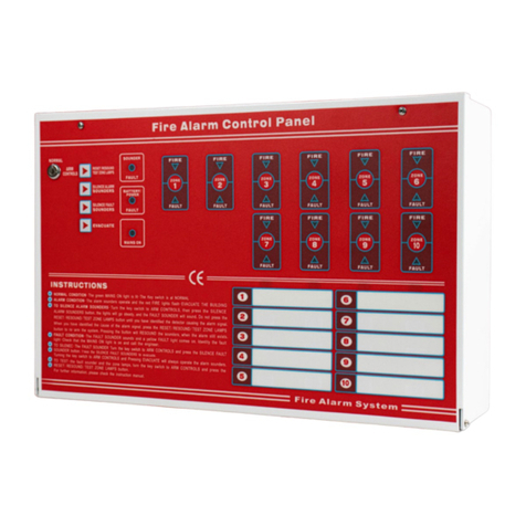
Telefire ADR-7000 User manual

Control Panels
ADR-7000 / SAVER-7000 /
GUARD-7
Addressable
Fire Alarm Control Panel
Technical Manual
TELEFIRE FIRE &GAS DETECTORS LTD
PO Box 7036
Petach Tikva 49250
Israel
Tel: 972 3 970 0400
Fax: 972 3 921 1816
Web: www.telefire.com
ADR-7000En 98.pdf
Revision 0.98
October 2017

i
Note
The terms “Trouble” as used in NFPA 72 guideline and UL standards and
“Fault” as used in EN 54 standards are used interchangeably throughout this
manual.
i
Note
Do not install, operate, and maintain this ADR-7000 before fully reading this
manual.
© 2017 –2017 Telefire Fire & Gas Detectors Ltd.

ADR-7000 / SAVER-7000 / GUARD-7
© 2017 –Telefire Fire & Gas Detectors Ltd Revision 0.98 October 2017
—I—
Table of Contents
1INTRODUCTION............................................................................................1
1.1 SAVER-7000 AND GUARD-7 DIFFERENCES................................................... 2
2ADR-7000 CONTROL PANELS ....................................................................3
2.1 MAIN BOARD –ADR-7021.............................................................................. 4
2.2 SLC LINE CARD –ADR-7002.........................................................................4
2.3 KEYBOARD AND DISPLAY MODULE –ADR-7003 ..............................................5
2.4 POWER SUPPLY............................................................................................. 5
2.5 ZONE ALARM MODULE –ADR-7000ZM ..........................................................5
2.6 NETWORK COMMUNICATION MODULE –LON-7000..........................................5
2.7 TCP/IP MODULE –NET-7000........................................................................ 6
2.8 LOOP EXPANSION CARD –ADR-7001EM1 –ADR-7000 ONLY.........................7
2.9 REMOTE ANNUNCIATOR –RM-7000................................................................ 7
2.10 ACCESS LEVELS ............................................................................................8
3WORK STATES –ALARM, FAULT, SUPERVISORY, DISABLEMENT,
AND TEST MODES .....................................................................................10
3.1 NORMAL (QUIESCENCE)STATE..................................................................... 10
3.2 ALARM STATE.............................................................................................. 10
3.3 FAULT STATE............................................................................................... 12
3.4 SUPERVISORY STATE................................................................................... 12
3.5 DISABLEMENT STATE ................................................................................... 13
3.6 TEST STATE................................................................................................. 14
3.7 STATUS STATE ............................................................................................ 14
4INSTALLATION ...........................................................................................15
4.1 PRE-INSTALLATION PLANNING....................................................................... 15
4.2 CABLE PLANNING......................................................................................... 17
4.3 WIRING ....................................................................................................... 21
4.4 INSTALLATION OF DETECTORS,I/O MODULES,AND OTHER MODULES ............. 21
4.5 POST-INSTALLATION..................................................................................... 27
5AUTOMATIC EXTINGUISHING...................................................................30
5.1 EXTINGUISHING OUTPUT AND EXTINGUISHING CONTROLLER........................... 30
5.2 MANUAL ACTIVATION.................................................................................... 30
5.3 EXTINGUISHING DELAY................................................................................. 30
5.4 EXTINGUISHING DISCONNECT ....................................................................... 31
5.5 EXTINGUISHING NOTIFICATION AND ACTION TO PERFORM AFTER RELEASE...... 31

ADR-7000 / SAVER-7000 / GUARD-7
© 2017 –Telefire Fire & Gas Detectors Ltd Revision 0.98 October 2017
—II —
6DISPLAY AND KEYBOARD........................................................................33
6.1 LCD DISPLAY .............................................................................................. 33
6.2 LEDS.......................................................................................................... 34
6.3 OPERATOR KEYS ......................................................................................... 36
6.4 NUMERICAL AND ARROW KEYS ..................................................................... 37
7SYSTEM CONFIGURATION (PROGRAMMING) PROCESS......................38
7.1 MENU STRUCTURE....................................................................................... 38
7.2 ENTERING CONFIGURATION STATE ............................................................... 39
7.3 CONFIGURATION PROCESS........................................................................... 39
7.4 SAVING THE CONFIGURATION AND EXIT OUT OF SYSTEM CONFIGURATION ...... 39
8SYSTEM CONFIGURATION (PROGRAMMING) ........................................41
8.1 SYSTEM CONFIGURATION............................................................................. 41
8.2 ENABLEMENT /DISABLEMENT ....................................................................... 42
8.3 MONITOR..................................................................................................... 44
8.4 SYSTEM REPORTS ....................................................................................... 44
8.5 UTILITIES..................................................................................................... 48
8.6 WALK TEST ................................................................................................. 51
8.7 SYSTEM VIEW.............................................................................................. 53
8.8 SMOKE CONTROL TEST................................................................................ 54
8.9 SYSTEM CONFIGURATION............................................................................. 54
8.10 DEVICE PROGRAM ....................................................................................... 61
8.11 CREATING DEVICE GROUPS.......................................................................... 64
8.12 DIAGNOSTICS .............................................................................................. 64
8.13 CLEAR REPORTS.......................................................................................... 64
8.14 CHANGE PASSWORDS.................................................................................. 65
8.15 ADVANCED .................................................................................................. 65
8.16 DETECTOR INITIALIZATION ............................................................................ 65
9TROUBLESHOOTING.................................................................................67
9.1 LEDS.......................................................................................................... 67
9.2 CONTROL PANEL ERROR MESSAGES ............................................................ 67
9.3 SYSTEM FAULTS .......................................................................................... 67
9.4 ADDRESSABLE DEVICE FAULTS..................................................................... 69
9.5 PROGRAMMING FAULTS................................................................................ 71
9.6 STATUS MESSAGES ..................................................................................... 73
9.7 CONTROL PANEL NETWORK FAULTS ............................................................. 73

ADR-7000 / SAVER-7000 / GUARD-7
© 2017 –Telefire Fire & Gas Detectors Ltd Revision 0.98 October 2017
—III —
10 PERIODIC TESTS........................................................................................74
10.1 WEEKLY TEST –DONE BY SITE SUPERVISOR................................................. 74
10.2 BATTERY TEST............................................................................................. 74
11 WARNINGS AND LIMITATIONS.................................................................75
12 COMPATIBILITY..........................................................................................76
12.1 INPUT DEVICES............................................................................................ 76
12.2 OUTPUT MODULES....................................................................................... 76
12.3 UL LISTING.................................................................................................. 77
13 SPECIFICATION..........................................................................................78
13.1 GENERAL SPECIFICATION ............................................................................. 78
13.2 POWER SUPPLY........................................................................................... 78
13.3 REMOTE ANUNCIATORS................................................................................ 78
13.4 MAIN BOARD –FIELD CONNECTION............................................................... 78
13.5 MAIN BOARD –RELAYS ................................................................................ 79
14 CERTIFICATION..........................................................................................80
APPENDIX A –CURRENT CONSUMPTION AND BATTERY CAPACITY
CALCULATION............................................................................................81
WHEN ARE AUXILIARY POWER SUPPLIES NEEDED?................................................... 84
APPENDIX B –DETECTOR SENSITIVITY SELECTION..................................85
14.1 SMOKE DETECTOR SENSITIVITY SETTINGS .................................................... 85
14.2 HEAT DETECTOR SENSITIVITY SETTINGS....................................................... 85
14.3 MULTI-SENSOR DETECTORS SENSITIVITY SETINGS........................................ 85
APPENDIX C –STANDARDS COMPLIANCE...................................................86
14.4 UL 864 COMPLIANCE................................................................................... 86
14.5 EN 54 –OPTIONS WITH REQUIREMENTS ....................................................... 86
14.6 EN 12094-1 COMPLIANCE............................................................................ 87
14.7 CP-10......................................................................................................... 87

ADR-7000 / SAVER-7000 / GUARD-7
© 2017 –Telefire Fire & Gas Detectors Ltd Revision 0.98 October 2017
—IV —
UL 864 Compatibility
Telefire's ADR-7000 product line complies with the requirements of several standards,
including UL 864, IS 1220, EN 54, EN 12094, and GOST, and may comply with options
or requirements of one of the standards and are not compliant with another standard.
Where the control panel allows setting of a parameter that are outside the range of one
of the standards, we included an appropriate warning in the relevant area of the manual.
Parameter
Allowed?
Possible Range
Range per UL 864
Alarm verification
by delayed
confirmation
Yes
0-50 seconds
0-60 seconds
Do not combine time-based
alarm verification and cross
zone alarm verification
Alarm verification
by cross-zone
Yes
Cross zone or no
verification
Cross zone or no verification
Do not combine time-based
alarm verification and cross
zone alarm verification
Delay of releasing
Yes
0-50 seconds
0-60 seconds
Delay of first fault
in an addressable
device
Yes
0-240 seconds
0-180 seconds
Delay of buzzer
notification of loss
of AC power
Yes
0-240 minutes
0-3 minutes (0-180 seconds)
Keyboard locking
Yes
Continuously; after
10 minutes; after
30 minutes; after
an hour
0-30 minutes
UL
UL 864 paragraph 59.1 Compliance
The following products mentioned in this manual were not tested or listed by
UL and should not be installed where UL listing is required:
TFH-280A and TFH-220A (Heat Detectors)
ADR-812A and ADR-818A (Input modules)
ADR-828A (LED Driver)
TPS-34A (auxiliary power supply)
TIP-224A (Sounder)
ADR-833A (Extinguishing controller)
TPH-482A and TPH 442A (photo / heat multi-sensor detectors)
Use a UL listed equivalent product where required.

ADR-7000 / SAVER-7000 / GUARD-7
© 2017 –Telefire Fire & Gas Detectors Ltd Revision 0.98 October 2017
–Page 1 of 87 –
1 Introduction
Telefire's ADR-7000 Advanced Addressable Control Panel is a UL 864 compliant system
that can be used as a standard fire detection and alarm system including sprinkler
supervision; fire detection and extinguishing release system; fireman phone system; a
compliant smoke control.
The ADR-7000 control panel monitors addressable initiating devices such as smoke
detectors; heat detectors; manual fire alarm call points; and flow switches. It also
monitors and activates output devices such as sounders; strobes; indicating signs; etc.
The base control panel is modular and can be configured with 1, 2, 3, or 4 Class A or
Class B loops. An expansion module allows extending the system by up to 4 additional
loops (8 loops in total). The ADR-7000 includes two reversed-polarity notification alarm
circuits (NACs) and three programmable dry contact Form C relays; 24Vdc outputs to
devices that require additional 24Vdc supply are also included.
Up to 32 ADR-7000 control panels can be networked in a single peer-to-peer network.
Each control panel is capable to communicate with up to 16 RM-7000 digital
annunciators via an RS-485 interface.
The ADR-7000 has a built-in 150W power supply. Auxiliary 24Vdc to devices is
expandable to hundreds and even thousands of watts using UL listed power supplies
that can be distributed to avoid costly power losses over long cables.
All inputs and outputs are fully supervised. Outputs are monitored for over-current and
are disconnected automatically when the current drawn from them exceeds the specified
amount.
Input and output protection is done without the use of fuses, using an advanced current
management that allows for high resilience of the system when encountering a shorted
output and automatic return to normal operation when the short is resolved.
Telefire's ADR-7000 has a highly resilient power supply system, ensuring that a short on
any input or output (including those located on SLC-connected I/O modules) affects only
the specific point, and does not disable all devices that feed from the same 24Vdc
supply.
It is possible to connect conventional initiating devices to the system via addressable
input (monitor) modules. Conventional output devices may be connected via
addressable NAC output modules.
Strobes connected to NAC outputs are synchronized at the control panel level (i.e., all
strobes connected to an ADR-7000 are synchronized, regardless of the loop they are
connected to). Strobes can be connected without protocol (i.e., two NACs activate
separately the sounders and the strobes), or with protocol (i.e., a single pair of wires
from the NAC to the sounder/strobe control both sounder and strobe via protocol). The
ADR-7000 supports both Wheelock and Gentex protocols.
Every device in the system is individually monitored and controlled for all parameters
such as day and night alarm sensitivity, pre-alarm, operation mode (quiescence, alarm,
fault, and maintenance mode).
The control panel performs automatic drift compensation to adjust the detectors
sensitivity and compensate for changes due to changes in environmental conditions and
dust accumulation. The ADR-7000 includes a maintenance fault feature that alerts the
user when a detector requires cleaning.
Detailed LED indication and a user-friendly graphic LCD provide clear display of the
system's status.

ADR-7000 / SAVER-7000 / GUARD-7
© 2017 –Telefire Fire & Gas Detectors Ltd Revision 0.98 October 2017
–Page 2 of 87 –
Each event is clearly detailed and allows for a quick and convenient identification of
alarms and faults to the end user, installer, and service technicians. Optional modules
allow for zone indication.
All configuration programming may be done via the built-in keyboard or with Telefire-
proprietary PC-based software. The ADR-7000's sophisticated microprocessor allows
easy configuration and modification in the field without the use of dedicated tools, while
providing access only to authorized personnel.
Figure 1 Typical ADR-7000 System
1.1 SAVER-7000 and GUARD-7 Differences
The SAVER-7000 is similar to the ADR-7000, but is stand-alone and can only have 2
loops and up to 3
RM-7000 remotes
The GUARD-7 is a stand-alone control panel that is limited to 60 addresses and can
only have 2 loops and up to 3 RM-7000 remotes

ADR-7000 / SAVER-7000 / GUARD-7
© 2017 –Telefire Fire & Gas Detectors Ltd Revision 0.98 October 2017
–Page 3 of 87 –
2 ADR-7000 Control Panels
The ADR-7000 control panel provides user-friendly operation. The keyboard and the
display that are mounted on the front panel contain an illuminated 260-by 64 pixel
graphical LCD, LED indicators for major events, and functional keys. Access to all
operations is secured by multi-level passwords.
The interior section of the cabinet is secured by a key-lock. It contains a power supply,
the main board, line card(s), battery compartment space, and optional communication
modules.
The ADR-7000’s main board can contain one to four ADR-7002 line cards, enabling
control of as many as 508 addressable initiating devices, notification appliances and I/O
modules. Each line card can be configured as a Class B or Class A loop.
An optional expansion modules allows the installation of up to four additional
ADR-7002 line cards (up to 1,016 addresses per control panel).
The system can be expanded beyond the base control panel by networking. An optional
LON-7000 network communication module allows the connection of as many as 32
control panels to set up a peer-to-peer network. With appropriate programming each
control panel on the network is able to respond to alarm and trouble events that occurred
in other control panels.
The control panel has an integral real time clock and calendar that enables day and
night sensitivity setting for each addressable detector according to weekly operation
schedule and working hours. Daytime and nighttime hours can be programmed
independently for each day of the week, as well as national holidays.
Events such as alarm, trouble, silencing, reset, programming, etc., are stored in the
ADR-7000’s memory in the order in which they occur, creating event-list history. An
event record contains date, time, device type, and additional details. Event records can
be displayed on screen and printed as a report.
All operations and configuration can be performed either from the system’s front panel or
from a PC. Telefire’s user-friendly proprietary programming and control software
(running on Windows™ operating system) allows operators/installers to easily configure
any system parameter using its advanced graphical interface.
ADR-7000 control panel for a variety of communication interfaces that allow control and
monitoring;
RS 232 connection to a computer, NET-7000 TCP/IP module for control and
monitoring via a local (LAN) or global (WAN) area network
RS-485 for Class B or Class A connection to remote annunciators
USB connector for connecting to a computer

ADR-7000 / SAVER-7000 / GUARD-7
© 2017 –Telefire Fire & Gas Detectors Ltd Revision 0.98 October 2017
–Page 4 of 87 –
Figure 1 Schematic ADR-7000 subassemblies
2.1 Main Board –ADR-7021
The ADR-7000's ADR-7021 main board is designed for ease of installation and
maintenance. Connectors are located in logical groups; on the left are the input from the
power supply and battery connection; three dry contact relays; and a connector for
changing the addresses of addressable modules. On the bottom are the two general
purpose NACs; SLC loops; 24Vdc supply to the field; and dialer activation and voltage
supply. On the right are the display / keyboard connector; LON-7000 networking
module; an RS-232 port for NET-7000 TCP/IP module, and a connector for the remote
annunciator units.
2.2 SLC Line Card –ADR-7002
Up to four ADR-7002 line cards line cards are mounted on the ADR-7021 main board
and control the bi-directional communication between the control panel and the
addressable devices on the SLC loop.
The loop is electronically protected against shorts, and will be automatically
disconnected if a short is sensed. Each line card can be configured to work in a Class B
or Class A loop.
Two LEDs for each loop indicate loop condition and serve installers and technicians:
The red LED flashes each time a device is addressed
The yellow LED flashes when a fault is detected, even after a momentary
interference that would not activate a trouble condition
2.2.1 Maximum Addresses –ADR-7000
All loop cards are capable of communicating with up to 127 addresses, and the
maximum number of addresses is a 1,016 single control panel.
Line Cards
Max. Addresses
Line Cards
Max. Addresses
1
127
5
635
2
254
6
762
3
381
7
889

ADR-7000 / SAVER-7000 / GUARD-7
© 2017 –Telefire Fire & Gas Detectors Ltd Revision 0.98 October 2017
–Page 5 of 87 –
Line Cards
Max. Addresses
Line Cards
Max. Addresses
4
508
8
1,016
Table 1 Maximum addresses by configuration –ADR-7000
2.2.2 Maximum Addresses –SAVER-7000
All loop cards are capable of communicating with up to 127 addresses, and the
maximum number of addresses is a 254.
Line Cards
Max. Addresses
1
127
2
254
Table 2 Maximum addresses by configuration –SAVER-7000
2.2.3 Maximum Addresses –GUARD-7
The GUARD-7 has 60 addresses.
2.3 Keyboard and Display Module –ADR-7003
The keyboard and display module contains a graphic LCD display (240 x 64 pixels),
indicating LED display, and keys for programming and operation. The display and
keypad meet the strict standards of UL 864, EN 54, and IS 1220.
The display and keypad have six main areas:
Graphic LCD display
General display area
Fault display area
Additional indication area
Keyboard
Zone indication LEDs
See detailed explanations on page 22.
2.4 Power Supply
The ADR-7000 has a 150W power supply that accepts 110-240Vac (nominal) input.
2.5 Zone Alarm Module –ADR-7000ZM
The optional Zone Alarm Module may be installed in the ADR-7000 to visually indicate
zones in alarm.
2.6 Network Communication Module –LON-7000
The LON-7000 is a communication module that enables connection between control
panels to establish a network. A two-wire copper cable connection is required to
interconnect between the control panels. Optionally fiber-optic connection is made
possible with additional modules. The length of the wires depends on the connection
topology and media type (copper or fiber optic). Please refer to the LON-7000 technical
manual for further details.

ADR-7000 / SAVER-7000 / GUARD-7
© 2017 –Telefire Fire & Gas Detectors Ltd Revision 0.98 October 2017
–Page 6 of 87 –
Figure 2 LON-7000 Networking communication module (ADR-7000 only)
i
Note
Ensure that all panels in a network have the same software version and all
LON-7000 modules are identical (both hardware and software).
2.6.1 Topology
An ADR-7000 LonWorks network can connect from 2 and up to as many as 32
ADR-7000 control panels in a peer-to-peer or Master-slave network. The physical
topology of the network may be bus (figure 8), ring (figure 9) or free (figure 10) topology.
Logical hierarchy may be peer-to-peer –where all messages are reported in all control
panels, master/slave –where slave messages are reported on master control panels, or
a combination of the two.
Ring topology requires LRW-102 Fiber Optic Repeaters.
Please refer to the LON-7000 technical manual for further details.
2.7 TCP/IP Module –NET-7000
The ADR-7000's internet-enabled features allow it to provide fire alarm control panel
monitoring over LAN, WAN, or Internet using a standard web browser or Telefire's
proprietary TCS-3040 software, and distribute alarm and trouble events via a built-in web
server, e-mail notification and SMS paging.

ADR-7000 / SAVER-7000 / GUARD-7
© 2017 –Telefire Fire & Gas Detectors Ltd Revision 0.98 October 2017
–Page 7 of 87 –
Figure 3 Remote control by TCP/IP NET-7000 module
2.8 Loop Expansion Card –ADR-7001EM1 –ADR-7000 only
The loop expansion card is designed for ease of installation and maintenance.
Connectors are located in logical groups; on the left are the data and power inputs from
the main board. On the bottom are connectors for SLC loops 5-8; and Ground and
24Vdc supply to the field.
The ADR-7001EM1 card supports 1 –4 additional SLC loops.
2.9 Remote Annunciator –RM-7000
The RM-7000 Remote Panel and Annunciator enables control and supervision of the
ADR-7000 fire alarm control panel from remote locations and key positions such as
security officer, premises manager, or maintenance office.
The RM-7000 remote panel consists of an LCD display, keyboard, internal buzzer, and
features such as alarm output, trouble output, and an interface relay that reduces the
need for additional input/output interface modules.
The remote panels are connected to the main control panel via a twisted wire pair
(RS-485). As many as 16 remote panels can be connected to the control panel using
the same cable in a Class B or Class A configuration. Each remote panel should be
configured with a unique address in the range of 1 to 16. The communication circuits
are fully supervised.
In large systems incorporating several control panels connected via a peer-to-peer
network as many as 16 remote panels can be connected to each of the control panels.
The RM-7000 operates with a 24Vdc power source that can be supplied from the main
control panel or an auxiliary power supply such as Telefire's TPS-73A or TPS-34A
Addressable Auxiliary Power Supply.
Please refer to the RM-7000 technical manual for further details.

ADR-7000 / SAVER-7000 / GUARD-7
© 2017 –Telefire Fire & Gas Detectors Ltd Revision 0.98 October 2017
–Page 8 of 87 –
2.10 Access Levels
The control panel allows protection from unauthorized access through protection of
certain functions by various access levels.
The control panel includes an electronic locking mechanism that allows work in 4 access
levels:
Access level 1 –not limited by password
Access level 2 (operator) –protected by password. Provides all of access level 1
functions and allows access to additional functions that are performed on a regular
basis by the system operator
Access level 3 (programmer) –protected by password. Provides all of access
level 2 functions and allows access to additional functions such as configuration and
programming
Access level 4 (manufacturer) –protected by dedicated tool
There are six users, each of which has a different password:
User
Position
User 1
Security guard
User 2
Operator –an employee of building owner or manager that has undergone
user training
User 2
Operator –an employee of building owner or manager that has undergone
user training
User 3
Programmer –someone who is qualified to install and configure the system
User 5
Programmer –someone who is qualified to install and configure the system
User 6
Master Programmer –a senior person who is qualified to install and
configure the system
Action
User 1
Users 2
and 3
Users 4 and
5
User 6
Guard
Operator
Programmer
Senior
Programmer
Scrolling events
Silence buzzer
Silence sounders
Reset
Device address
programming
Enable / disable device
Walk test
Setting time and date
Setting holiday dates
Control panel configuration

ADR-7000 / SAVER-7000 / GUARD-7
© 2017 –Telefire Fire & Gas Detectors Ltd Revision 0.98 October 2017
–Page 9 of 87 –
Action
User 1
Users 2
and 3
Users 4 and
5
User 6
Guard
Operator
Programmer
Senior
Programmer
Device programming
Keyboard unlock
Clearing extinguishing
activated sign
Can change password
for himself
for user 1
for users 2 and 3
for users 4 and 5
–
–
–
–
self only
–
self only

ADR-7000 / SAVER-7000 / GUARD-7
© 2017 –Telefire Fire & Gas Detectors Ltd Revision 0.98 October 2017
–Page 10 of 87 –
3 Work States –Alarm, Fault, Supervisory, Disablement,
and Test Modes
Alarm, fault or supervisory events are shown clearly by dedicated LEDs that are labeled
Fire, Fault, and Supervisory, respectively. A detailed explanation in the LCD display
includes all relevant details for troubleshooting and proper resolution of the event.
Fire alarms, fault conditions, and supervisory conditions are defined as events. When
two events occur at the same time, the first event will be shown (alarms have a higher
priority) and the event counters in the LCD display show the number of alarms,
supervisory events, status events, faults, disablements, and addresses in test mode.
Fire alarms have a higher priority than fault events and are shown first.
To see the events in the order they occur, use the up and down arrow keys.
3.1 Normal (Quiescence) State
Normal state is a state where no alarm or fault event and all of the inputs and outputs
are enabled. In this state, the green power LED is turned on and the LCD displays
System OK.
Screen 1 Quiescence state
3.2 Alarm State
Screen 2 Alarm state
3.2.1 Alarm Verification
The alarm verification feature allows the control alarm to ignore momentarily false
alarms that may cause a nuisance.
When an address is programmed for alarm verification, the control panel resets the
device in alarm, waits for 0 to 59 seconds (depends on individual address programming)
and rechecks whether the same address is still in alarm. During that time, the control
panel will enter alarm state when receiving an alarm from the same or another address.
During alarm verification time, the control panel will enter alarm state immediately in
case that there is another alarm indication even if that address is programmed as alarm
verification.

ADR-7000 / SAVER-7000 / GUARD-7
© 2017 –Telefire Fire & Gas Detectors Ltd Revision 0.98 October 2017
–Page 11 of 87 –
In case only one alarm triggered the alarm verification clock, during and up to 120
seconds, no additional alarm is received, the clock will be reset and the control panel will
be back in normal mode.
3.2.2 Alarm Operations
During an alarm in one of the addresses, the control panel performs the following
operations
Indicating the address in alarm on the LCD display
Turning on the Fire LEDs in the LCD display and clarification area and the private
alarm zone in the zoning alarm
Displaying the alarm in the remote panel RM-7000 if connected
Logging an event in alarm history
Activating the NAC outputs in the panel
Activating dialer output
Activating internal buzzer
Activating relays that were configured as alarm relays
Activate output addresses as per matrix configuration
3.2.3 Acknowledge / Buzzer Off Operation
Silences the internal buzzer
UL 864
UL Models
For UL models, pressing the Acknowledge key will stop the flashing of the
LEDs and turn them solid on.
3.2.4 Acknowledge Operation
3.2.5 Silence Operation
Pressing the Silence key performs the following actions
Stops the action of the horn output
Stops the action of the internal buzzer
Stops the alarm relay if it was programmed as silenceable
Stops outputs that were programmed as silenceable
3.2.6 Action during a Second Alarm (Two Devices in Alarm at the
Same Time)
Screen 3 Two concurrent alarms
When receiving a second alarm, (i.e., two devices are in alarm at the same time), the
control panel perform the following operations
Reactivation of all silenced output

ADR-7000 / SAVER-7000 / GUARD-7
© 2017 –Telefire Fire & Gas Detectors Ltd Revision 0.98 October 2017
–Page 12 of 87 –
Increase the event counters on the LCD display.
Activating outputs that were programmed to activate upon an alarm from these
devices
3.2.7 Resetting an Alarm
Resetting an alarm can be done by pressing the Reset key.
3.3 Fault State
Screen 4 Fault state
A fault in the system will be shown indicated in the system by a flashing yellow LED in
addition to the fault information in the LCD display.
3.3.1 Actions Taken in Fault State
When receiving a fault event at the control panel, the control panel will perform the
following operations
Indicating the fault in the display
Turning on the General Fault LED
Activating the internal buzzer in the control panel
Logging an event in fault history
Activating relays that were configured fault relays
3.3.2 Actions Taken Upon Event Confirmation (Pressing the "#"
Key)
Stopping LED indicator flashing, - the LEDs shall stay on until the issue is resolved
3.3.3 Actions Taken Upon Pressing "Buzzer Off" Key
Silencing the internal buzzer
Stopping the flashing of the LEDs in the general alarm area and turning them solid
on (UL version only)
3.4 Supervisory State
Screen 5 Supervisory state
The ADR-7000 has a supervisory function that conforms to UL and EN standards.

ADR-7000 / SAVER-7000 / GUARD-7
© 2017 –Telefire Fire & Gas Detectors Ltd Revision 0.98 October 2017
–Page 13 of 87 –
In certain cases, there is a need to activate an output following a fault such as indication
of low pressure in an extinguishing cylinder, closed sprinkler valve, etc.
The supervisory function answers these need and allows monitoring switch conditions
and reaction according to the state were using the fire alarm infrastructure.
Supervisory fault does not latch –at the end of the event, the system goes back to
normal state without intervention.
3.4.1 Action Taken Upon a Supervisory Event
A supervisory event will cause the following events in the control panel
Turning on the supervisory LED, the supervisory indication in the LCD display
Indicating the fault event in the RM-7000 remote panel if connected
Activating fault buzzer
Logging of the event in the fault history
Activating supervisory outputs that are in the same logical zone as the activated
fault supervisory device, if defined
Activating supervisory relays, if defined
3.4.2 Actions Taken Upon Pressing "Buzzer Off" Key
Silencing the internal buzzer
Stopping the flashing of the LEDs in the general alarm area, in the LCD display and
clarification area and the private LEDs in the zones and turning them solid on
UL 864
UL Models
For UL models of the ADR-7000, pressing the Acknowledge key stops the
flashing of the LEDs in the general alarm area, in the LCD display and
clarification area and the private LEDs in the zones and turning them solid on.
3.5 Disablement State
Screen 6 Disablement state
Sometimes there is temporarily a need to disable a particular input, output, or relay.
The control panel will ignore alarms from disabled devices or zones and will not activate
disabled outputs or relays.
When one of the devices, zones or outputs is disable, the disabled LED is turned on to
indicate this status.

ADR-7000 / SAVER-7000 / GUARD-7
© 2017 –Telefire Fire & Gas Detectors Ltd Revision 0.98 October 2017
–Page 14 of 87 –
3.6 Test State
Screen 7 Test state
Test state allows testing the control panel without activating outputs. This state is
indicated by the Test LED.
See page Error! Bookmark not defined. for additional information about Field Test.
3.7 Status State
Screen 8 Status state
Status state indicates events that are not alarm, supervisory, fault, disablement, or test
states.
These events include:
Evacuation
Pre-alarm
A call on the fireman phone system
Extinguishing abort
A loudspeaker selection switch activation
Status change of a manual selector on a smoke panel
Status report from a blower or damper in a smoke system
This manual suits for next models
2
Table of contents
Other Telefire Control Panel manuals
Popular Control Panel manuals by other brands
Honeywell
Honeywell GX-Series Installation and setup guide
weintek
weintek MT607iE Installation instruction

Siemens
Siemens SCD 1297-K (33) Operating instruction
Extron electronics
Extron electronics MLC Plus 84 EU Setup guide

Honeywell
Honeywell AQ255 Series Product data
tecnoelettra
tecnoelettra TE805 manual
