Teleflex Marine CH2200ENC User manual
09/2006 Page 1 of 6 ISCH2200ENC_Rev_0
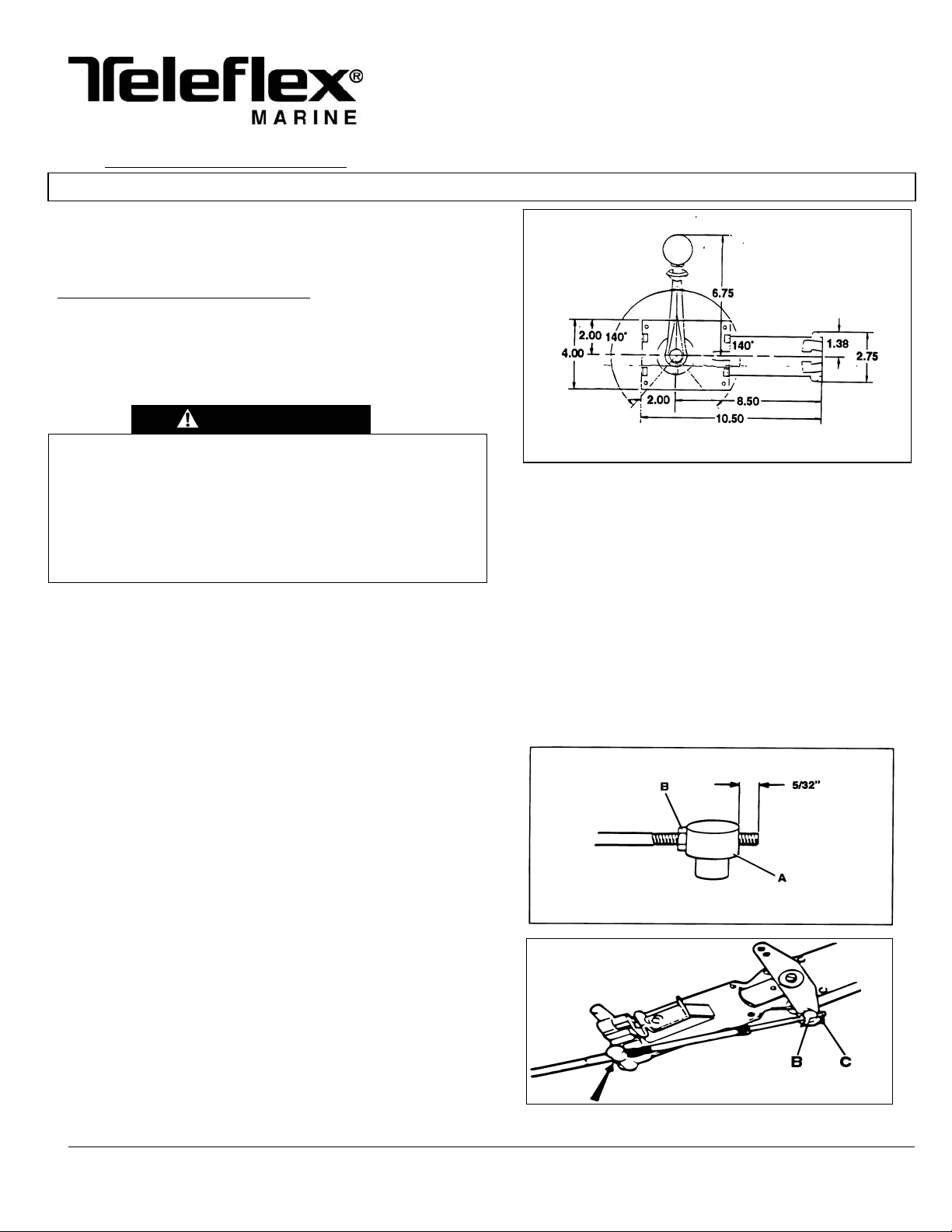
1. Select a location for the control ensuring that the handle does not
interfere with dashboard, steering wheel, seat, switches, or other
equipment at any point in its travel. NOTE: THICKNESS OF
MOUNTING SURFACE MUST NOT BE GREATER THAN ½”.
Also ensure that the shift cable will have at least 36 inches of
unrestricted space for movement (see INSTALLATION OF
SHIFT CABLE). Refer to Figure 1 for dimensions and
clearances. NOTE: CONTROL CAN BE MOUNTED
HORIZONTALLY OR VERTICALLY TO FACILITATE CABLE
CLEARANCE.
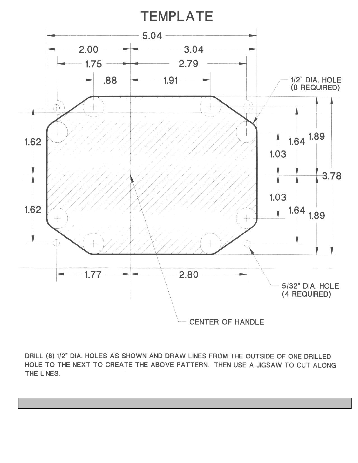
2. Cut mounting holes in selected location, using template provided.
3. If not already routed, route the shift cable and engine harness
to the cutout, allowing the cable and harness to protrude from
the cutout enough to allow connection to the control mechanism.
INSTALLATION OF SHIFT CABLE
1. BEND RADIUS
Minimum bend radius is 8”. If installed with sharper bends, cable
wear will increase rapidly.
2. SUPPORTING THE CABLE
DO NOT TIE OR CLAMP THE CABLE WITHIN 36 INCHES OF THE
CONTROL. WHEN SUPPORTING THE CABLE BEYOND 36
INCHES OF THE CONTROL, DO NOT TIE OR CLAMP TIGHTLY.
THESE INSTRUCTIONS DESCRIBE HOW TO
INSTALL THE CH2200ENC SERIES SIDE MOUNT
CONTROL.
A
DDITIONAL EQUIPMENT REQUIRED:
One Cable - P/Ns CC172XX and CC633XX (CC172 is a 3300-type
cable used for shift in all applications.)
Note: This control does NOT provide “Start in Gear” protection, which must
be provided by the engine manufacturer.
READ THESE INSTRUCTIONS THOROUGHLY BEFORE
STARTING INSTALLATION. FAILURE TO FOLLOW THESE
INSTRUCTIONS AS WELL AS THE INSTRUCTIONS PROVIDED
BY THE ENGINE MANUFACTURER MAY RESULT IN LOSS OF
ENGINE CONTROL WITH SUBSEQUENT PROPERTY DAMAGE
AND PERSONAL INJURY. DO NOT SUBSTITUTE PARTS FROM
OTHER CONTROL MAKERS, AS THEY MAY CAUSE A SAFETY
HAZARD FOR WHICH TELEFLEX, INC. CANNOT ACCEPT
RESPONSIBILITY.
PREPARATION FOR MOUNTING CONTROL
Figure 1
3. CONNECTION OF THE SHIFT CABLE
NOTE: ALWAYS CONNECT THE CABLE TO THE
MECHANISM BEFORE CONNECTING IT TO THE
ENGINE AND GEAR.
1. Push the shift cable through the appropriate retainer,
making sure the cable seats securely into the
retainer (Figure 3, item A).
2. Thread the pivot (Figure 2, item A) onto the cable
terminal until the threaded portion of the terminal
protrudes 5/32” (5 threads). Secure the pivot by
tightening the nut (Figure 2, item B).
3. Connect the pivot to the shifting lever (Figure 3, item
B) and secure with a cotter pin (Figure 3, item C).
Figure 2
A
CH2200ENC
SERIES SIDE MOUNT
SINGLE LEVER CONTROL
Copyright 2006 Teleflex Incorporated (USA) INSTRUCTIONS
Manufactured by
Teleflex Inc. U.S.A.
640 N. Lewis Road
Limerick, PA 19468 (USA)
610/495-7011
Figure 3
INSTALLER: THESE INSTRUCTIONS CONTAIN IMPORTANT SAFETY INFORMATION AND MUST BE FORWARDED TO THE BOAT OWNER.
WARNING

09/2006 Page 2 of 6 ISCH2200ENC_Rev_0
INSTALLATION OF WIRING HARNESS
A wire harness must be prepared for connection of the
CH2200ENC control head to the engine TAC module. Every
boat is different and there may be several ways to route the
harness. Inside the boat there is often a channel or conduit used
for wiring. This can also be used to route the wire harness for
the CH2200ENC control.
When routing the wiring harness, care must be taken not to
damage the cable insulation. If a harness is short, replace it with
a correct length harness. Don't add a short harness to make up
the required length. Run the harness over the shortest and
straightest possible path. Secure the harness every 2 feet (0.6
m) with stainless steel screws and mounting head ties or
clamps. Excess harness length should be neatly coiled and
secured with nylon ties. The mounted harness should be as far
as practical from high current wires or wiring runs and should
not be subjected to water, fuel, lubricants, or excess heat.
PREPARATION OF CONTROL HEAD WIRE HARNESS
Measure from the control head mounting location along
unobstructed wire runs to the engine module.
Round measurement to the next whole foot and add additional
length if uncertain.
Prepare harness as shown in Figure 5 [on page 3]. It is
recommended that conductors be stranded tinned copper (UL
1426 or equivalent), 18 AWG min. Colors shown are optional.
CONNECTION OF THE WIRING HARNESS
NOTE: ALWAYS CONNECT THE WIRING HARNESS TO THE
CONTROL HEAD BEFORE CONNECTING TO THE ENGINE.
ENGINE CONNECTION SHOULD NOT BE MADE UNTIL THE
CONTROL HAS BEEN COMPLETELY INSTALLED.
Ensure that the watertight seal is in place and connect the 6-pin
connector from the completed harness assembly into the rear of
the potentiometer mounted on the control head mechanism. The
connector should be fully seated and latched for proper
operation.
THROTTLE BRAKE ADJUSTMENT
The control mechanism is equipped with an adjustable friction
device (brake) for the throttle to prevent throttle creep. I
f
needed, the friction device can be adjusted by turning the
adjustment screw (Figure 4, item A) clockwise to increase
braking and counterclockwise to decrease or remove braking.
A
ny adjustments should be made with the control set at 1/2
throttle and the gear engaged. Gear shifting is not influenced
by the brake.
Figure 4
INSTALLATION OF CONTROL
A. INSTALLING THE MECHANISM
1. Make sure the control is in gear and at the half throttle
position. This will allow the control to fit in the cutout
shown in the template. If not already in half throttle
position, use the handle to move in gear and at half
throttle position by temporarily placing the handle on the
splined shaft of the control. Push the mechanism until it
seats flush against the mounting surface of the boat.
2. Secure the control mechanism to the boat with the four
screws provided.
A

09/2006 Page 3 of 6 ISCH2200ENC_Rev_0
PREPARATION OF CONTROL HEAD WIRE HARNESS
Figure 5
Del
p
hi Packard Website: www.del
p
hiconnect.com

09/2006 Page 4 of 6 ISCH2200ENC_Rev_0
B. INSTALLING THE COVER (IF SUPPLIED)
Once the mechanism has been securely mounted, the
handle assembly may be attached to the control. The
handle assembly contains two (2) sets of internal splines;
one (1) on the chrome locking ring, and one (1) on the black
handle. There are two (2) sets of mating external splines on
the mechanism; one (1) on the cast housing and one (1) on
the steel shaft. Each set of splines contains forty-eight (48)
teeth and both sets of the 1 3/8” splines and ¾” splines are
consistently oriented to the other (See Figure 6).
CONNECTION OF WIRING HARNESS AND SHIFT
CABLE CABLES TO ENGINE
1. Read engine maker’s manual and use the recommended
attachment kits to connect shift cable to the engine.
2. Connect the 10-pin connector from the wiring harness into
the engine TAC module. The watertight seal should be in
place and connector should be fully seated and latched
for proper operation.
KEEP THESE INSTRUCTIONS WITH YOUR BOAT FOR FUTURE REFERENCE.
4. Once the handle has been attached with the set screw,
insert the black button onto the push pin in the shaft and
press firmly. Insert the #6-32 x 7/8” long machine screw
through the center of the button and tighten until the screw
is flush with the button. Overtightening can result in
damaging the button and/or screw.
3. While applying pressure firmly against the assembly and
leaving the handle in the locked position, install the set
screw into the bottom of the handle and tighten.
1. Place the cover over the shaft and spline and snap into
place on the control mechanism.
C. INSTALLING THE HANDLE
1. Make sure the pinned rocker in the handle is situated in the
slot in the locking ring; this is referred to as the locked
position.
2. Firmly install the handle assembly onto the control so that
both sets of splines are fully engaged and the steel shaft
'bottoms-out' against the internal shoulder of the handle.
Since the splines on the shaft and handle wiII engage
before the splines on the locking plate and diecast housing,
make sure the locking ring rests securely on the 1 3/8”
splines and cannot rotate.
2. If the handle develops lost motion, check that it is firmly
attached the control body, that the control body is firmly
attached to the boat and that the cables are firmly
attached to the control, engine, and gear.
3. If stiffness of operation develops, disconnect cable from
the engine and check operation. If stiffness is due to
shift cable, it must be replaced.
1. Ensure that the control is firmly mounted.
A
lthough very little maintenance is required for this control
system, periodically check the following:
MAINTENANCE
IMPORTANT: ONCE THE ASSEMBLY HAS BEEN FULLY
A
TTACHED AND THE ENGINE TURNED OFF, LIFT THE
'UMBRELLA' OF THE HANDLE AND CYCLE THE HANDLE
THROUGH FULL FORWARD AND FULL REVERSE TO
ENSURE THAT BOTH SETS OF SPLINES ARE FULLY
ENGAGED. IF THE LOCKING PLATE IS CAPABLE OF
ROTATING WITH THE HANDLE, REMOVE THE HANDLE
A
SSEMBLY AND REPEAT THE HANDLE INSTALLATION
PROCEDURE. ALSO, CYCLE THE CONTROL USING THE
PUSH BUTTON/NEUTRAL WARM-UP TO ENSURE THAT
THE BLACK BUTTON HAS BEEN PROPERLY INSTALLED.
NOTE: Since the sets of splines are oriented and have the
same number of teeth, the control allows for the handle
assembly to be indexed every 7.5○. The centerline of the
handle is aligned with the centerline of the control, so if the
control is mounted horizontally, the handle can be attached
perpendicularly to the control.
PARTS LIST
ITEM DESCRIPTION QUANTITY
1 Handle 1
2 Locking Ring 1
3 Neutral Detent Warm-up Button 1
4 Button Mounting Screw 1
5 Control Mechanism 1
6 Control Mounting Screw 4
7 Knob 1
8 Handle Mounting Set Screw 1
9* Pivot, Small (3/16”) Dia. Thread 2
10 Cotter Pin (Figure 3, Item C) 1
*See Figure 2, item A
7
09/2006 Page 5 of 6 ISCH2200ENC_Rev_0
09/2006 Page 6 of 6 ISCH2200ENC_Rev_0
KNOB
SHIFTING THE CONTROL
To shift the control into forward or reverse, pull the umbrella up
toward the knob and advance the handle forward (for forward
travel) or rearward (for reverse travel) until the handle settles
into a detent at approximately 30○of travel (see Figure 8). At
this point, the control has engaged the gear and automatically
entered the throttle mode where further advancement of the
handle will increase the throttle. Once in the throttle mode, it is
no longer necessary to pull on the umbrella. Increase or
decrease throttle by simply moving the handle.
1. PUSH (AND HOLD)
BUTTON IN
2. PULL UMBRELLA UP
3. ADVANCE HANDLE
UMBRELLA
STEM
BUTTON
SHIFTING
FORWARD
SHIFT
POSITION
FIGURE 8
REVERSE
SHIFT
POSITION
NEUTRAL
POSITION
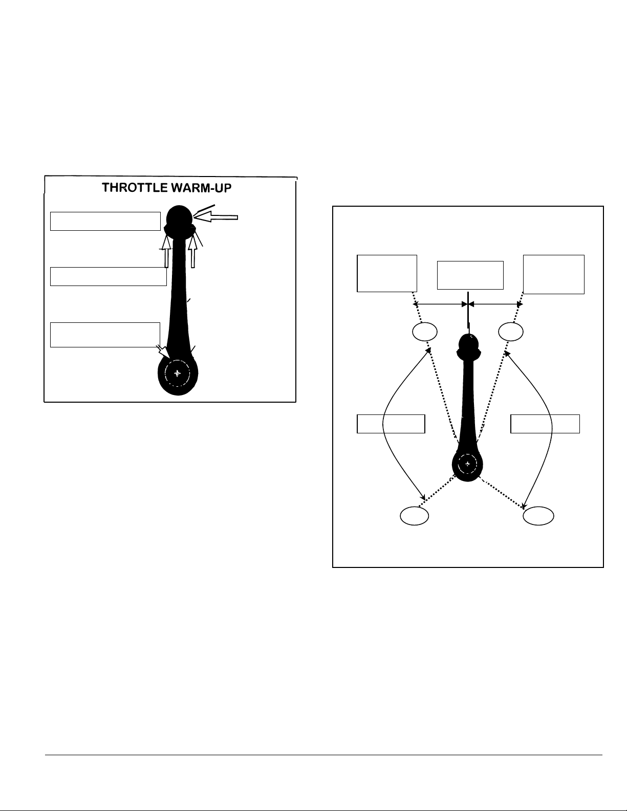
OPERATION OF CONTROL
THROTTLE WARM-UP IN NEUTRAL POSITION
To start the boat's engine and to activate the throttle for engine
warm-up, the handle must be in the neutral position. Neutral
can be found by rotating the handle (by grasping the knob or
stem) until the handle locks in position and can not be rotated
in either direction. Usually the handle is vertical as shown in
Figure 7 when in the neutral position.
FIGURE 7
Push in the button with your left hand while grasping the
umbrella and knob with your right hand and pull the umbrella
up toward the knob (see Figure 7). While still holding the
button and umbrella, advance the handle forward to put the
control in warm-up throttle mode. Once in this mode, the
button and umbrella can be released and throttle can be
adjusted by simply moving the control handle away from the
neutral position to increase throttle and towards the neutral
position to decrease throttle. Returning the handle to the
neutral position will disengage throttle warm-up.
THROTTLE THROTTLE
300
300
Table of contents
Other Teleflex Marine Marine Equipment manuals


