Teleflex Marine MV-3 Series User manual

INSTALLATION MANUAL
Page 1 of 12
Manual # 0550001-687 Revision 1
INSTALLATION AND OPERATION OF MV-3 SERIES
SIDE MOUNT CONTROL
OWNER’S MANUAL
For Single Station Only
These“saftey alerts” alone cannot elim-
inate the hazards they signal. Strict
compliance to these special instruc-
tions when installing, operating or
performing maintanence and using
common sence are the most effective
accident prevention measures.
Hazards or unsafe practices
which COULD result in sever
personel injury or death.
WARNING
!
NOTICE Throughout this manual, Warnings and Cautions, accompa-
nied by the International Hazard Symbol , are used to alert the manufacturer or installer to special
instructions concerning a particular service or operation that may be hazardous if preformed incor-
rectly or carelessly.
Warnings alone do not eliminate dangers, nor are the a substitute for safe boat handling and proper
accident prevention measures. Observe these alerts carefully!
!
DANGER
!
Immediate Hazards which
WILL result in severe
personel injury or death.
Hazards or unsafe practices
which COULD result in injury,
product and/or property
damage.
CAUTION
!NOTICE
Information that is important to
the proper installation,
operation and maintenance, but
is not hazard related.
INSTALLER: THESE INSTRUCTIONS CONTAIN IMPORTANT SAFETY INFORMATION AND MUST BE FORWARDED TO THE BOAT OWNER.

If the transmission shift function is different than the con-
trol shift arm, reposition the arm by removing hex head
screw and rotate the shift arm 180 degrees.
Pay attention to the 2-hole pattern on the shift arm for
mounting pivot. See Figure 3.
Repositioning Shift Arm
Control Configuration
TO DETERMINE THE CORRECT
CONTROL ASSEMBLY FOR
INBOARDS WITH HYDRAULIC
TRANSMISIONS, YOU MUST DE-
TERMINE IF THE SHIFT CABLE
“PULLS” OR “PUSHES” TO GO
INTO FORWARD AND IF THE
THROTTLE CABLE “PULLS”
OR “PUSHES” TO OPEN THE
THROTTLE.
NOTICE
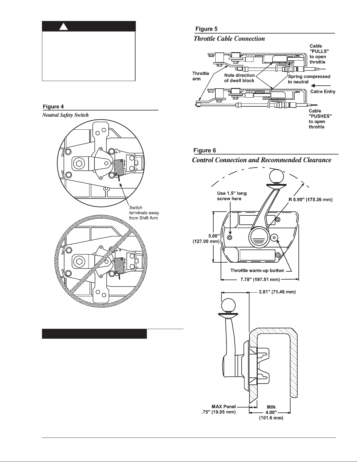
All MV-3 controls are assembled to give a “PULL” ac-
tion on the cable. If cable action is incorrect, reverse
throttle arm by removing Hex Head Screw and large
fl a t washer. Remove arm and reassemble in opposite
position as shown in Figure 5. Also, reverse position of
dwell block and spring by removing screw, flat washer
and nut. Reassemble in opposite position (see Figure
5).
CAUTION
!
IF THE SHIFT ARM IS
REPOSITIONED, THE NEUTRAL
SAFETY SWITCH MUST ALSO
BE REPOSITIONED OR THE
SWITCH WILL BE DAMAGED.
(SEE FIGURE 4.)
Reversing Throttle Action
CONTROLS
Choose a mounting location for the control head which will pro-
vide comfortable operation of the hand lever, unobstructed move-
ment of mechanism arms and a clear path for cables to engine.
Figure 6 shows the control dimensions and the recommended clearance
behind the mounting surface.
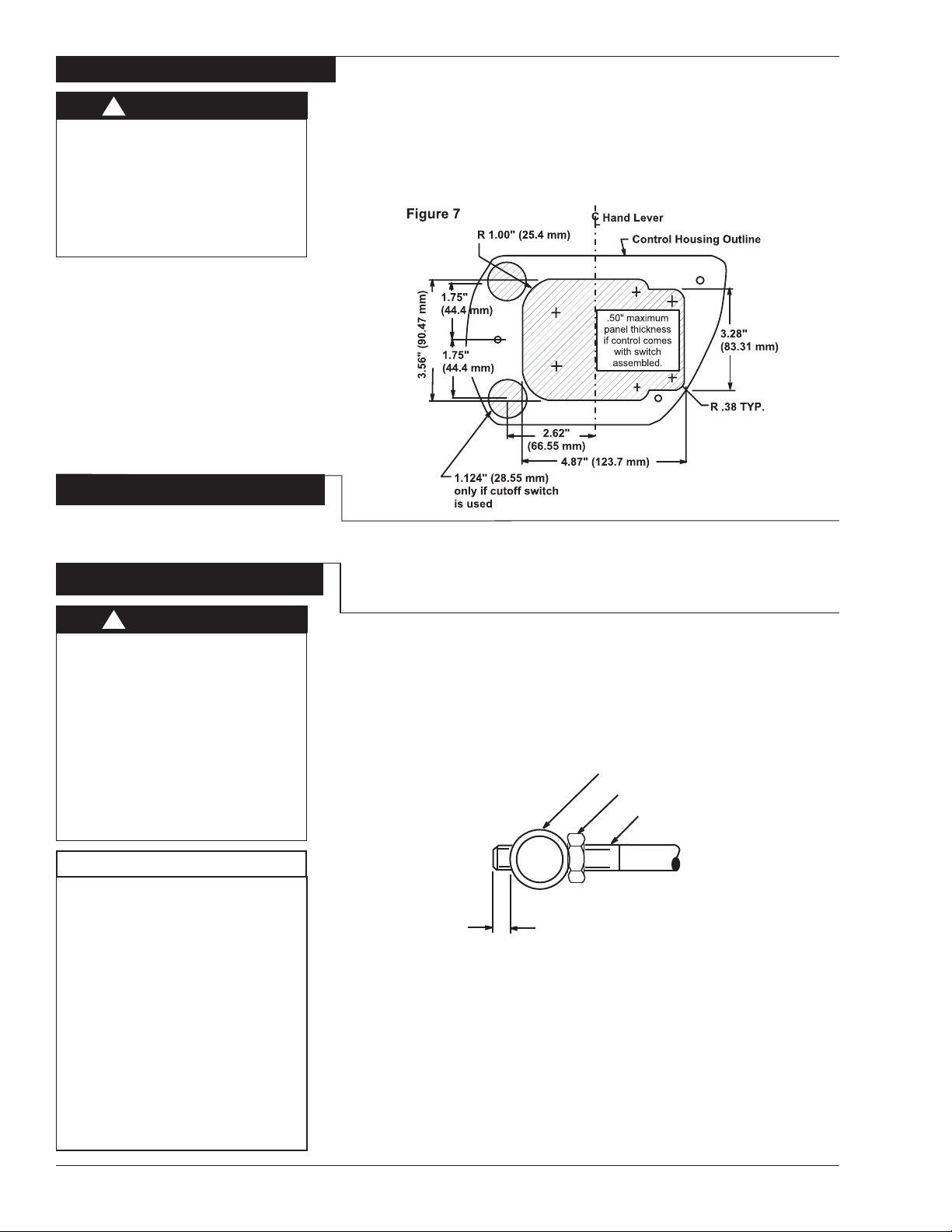
Using the template provided, cut the appropriate mounting hole in the
panel as shown in Figure 7.
Measure from the control head position along an unobstructed path to the
shift and throttle connections. Cable lengths are overall length. When a
measurement is in feet and inches, specify the next whole foot.
Connect Shift Cable To Control
Insert shift cable through opening in hanger assembly in line with shift
arm pivot attachment hole and lock cable in hanger slot.
Screw pivot onto cable rod, allowing threads to protrude through pivot
1/8” for standard travel or 1/4” for long travel.
Lubricate pivot with grease, then insert into required hole in shift arm
(see Figure 8). Fasten with cotter pin. Tighten cable nut against pivot.
To obtain standard (2 3/4” ) cable shift travel at engine, use shift arm
on control at short pivot hole location as shown in Figure 3.
For Mercury, long (3 inch) cable shift travel at engine is necessary. As-
semble shift arm to control using longest pivot hole location.
CAUTION
!
WHEN CONTROL COMES WITH
CUTOFF SWITCH INSTALLED,
PANEL THICKNESS MUST BE
.50” (12.7 MM) MAXIMUM. IF CUT-
OFF SWITCH IS NOT USED, THE
PANEL THICKNESS MAY BE .75”.
(19.05 MM) MAXIMUM.
Choosing Control Location
Measuring Cable Length
Connecting Shift Cable
CAUTION
!
THE PIVOT MUST BE IN THE HOLE
NEAREST TO CABLE ENTRY END
OF THE CONTROL.
USING THE HOLE IN THE SHIFT
ARM FURTHER MOST AWAY FROM
THE CABLE MOUNTING SUPPORT
WILL PRODUCE UNEQUAL SHIFT
TRAVEL BETWEEN “NEUTRAL TO
FORWARD” AND “NEUTRAL TO RE-
VERSE”, RESULTING IN IMPROPER
SHIFT ACTION.
(SEE FIGURE 3.)
NOTICE
THE CONTROL SHIFT LEVER AND
THE TRANSMISSION SHIFT LEVER
MUST COINCIDE AT THE FORWARD,
NEUTRAL AND REVERSE
POSITIONS.
DIFFERENT MAKES OF TRANSMIS-
SIONS MAY REQUIRE DIFFERENT
AMOUNTS OF SHIFT TRAVEL. FOR
THIS REASON, THE CONTROL
SHIFT LEVER IS PROVIDED WITH
TWO (2) POSITIONS FOR ATTACH-
ING THE SHIFT CABLE: ONE FOR
THE STANDARD TRAVEL AND ONE
FOR THE LONGEST TRAVEL. (SEE
FIGURE 3)
Figure 8 Brass pivot
Cable jam nut
Cable rod
.125" (3.17 mm) Standard travel
.25" (6.35 mm) Long travel
With opening in swivel bracket nearest to the cable entry end of the
control, insert throttle cable through opening in swivel bracket and
secure cable hub in bracket slot.
Screw pivot onto cable rod and allow cable rod threads to protrude
through pivot 1/8 inch (3.17mm).
Lubricate pivot with grease, then insert into hole in throttle arm. Fasten
with cotter pin. Tighten cable nut against pivot.Section 4
Neutral Safety Switch
Most MV-3 controls are equipped with a neutral safety switch.
With the Control in NEUTRAL, connect one wire of the tester to the com-
mon terminal and one wire to the “NC” (Normally Closed) Ter minal. The
test light MUST light.
Connect the Neutral Safety Switch between the ignition switch (start lead)
and the starter solenoid. (See Figure 9.) Use terminals with insulators to
insure against an electrical short circuit.
Cable Path
Run the cables, which are connected to the control, back to the throttle
and shift location of the engine and drive.
The cables should run as straight as possible, avoiding any sharp bends.
Make no bends in the cable of less than 8 inch (203.2 mm) radius.
NOTICE
TELEFLEX MARINE CONTROLS
STRONGLY RECOMMENDS
THAT THE SWITCH BE CON-
NECTED TO ASSURE SAFE
BOATING OPERATION.
NC
CAUTION
!
CHECK TO MAKE SURE THAT
THERE IS ELECTRICAL CONTI-
NUITY ONLY WHEN THE
CONTROL IS IN NEUTRAL.
WHEN THE CONTROL IS IN
GEAR, THERE MUST NOT BE
ANY ELECTRICAL CONTINU-
ITY.
Figure 10
24.0" (609 mm)
Minimum
Loose tie
Allow 4.0" (101 mm)
for cable movement
Swivel
Bracket
Connect Throttle Cable
Mount Control
Other Teleflex Marine Marine Equipment manuals


