Teleflex TFX160 User manual

TFX16 0
Operations M anual

Thank you for choosing Teleflex Sonar, manufactured by Techsonic
Industries, for your sonar fishfinder and depthsounder. Techsonic has built
its reputation by designing and manufacturing top-quality, thoroughly
reliable marine equipment. Techsonic has designed your Teleflex Sonar
unit to be trouble free even in the harshest marine environments.
In the unlikely event that your Teleflex Sonar product does require repairs,
Techsonic offers an exclusive Service Guarantee - free of charge during
the first year after purchase, and available at a reasonable rate after the
one-year period. Complete details are included at the end of this manual.
We encourage you to read this operations manual carefully in order to
get full benefit from all the features and uses of your Teleflex Sonar
product. Also, to register your purchase and help us learn more about
you, please fill out the included w arranty registration card
WARNING! This device should not be used as a navigational aid to
prevent collision, grounding, boat damage, or personal injury.
When the boat is moving, w ater depth may change too quickly to
allow time for you to react. Alw ays operate the boat at very slow
speeds if you suspect shallow w ater or submerged objects.
THAN K Y OU
WARNI NG:
Dis-assembly and repair of this electronic unit should only be performed by authorized
service personnel. Any modification of the serial number or attempt to repair the original equipment or
accessories by unauthorized individuals will void the warranty. Handling and/or opening this unit may result
in exposure to lead, in the form of solder.
WARNI NG: This product contains lead, a chemical known to the State of California to
cause cancer and birth defects and other reproductive harm.

Section 1: INSTALLATION PREPARATION . . . . . . . . . . . . . . . 2
Parts Supplied . . . . . . . . . . . . . . . . . . . . . . . . . . . . . . 2
Accessories . . . . . . . . . . . . . . . . . . . . . . . . . . . . . . . . 2
Installation Overview . . . . . . . . . . . . . . . . . . . . . . . . . 2
Alternative Transducers and M ounting M ethods. . . . . . 4
Section 2: USING THE
160
. . . . . . . . . . . . . . . . . . . . . . . . . 5
160
Performance . . . . . . . . . . . . . . . . . . . . . . . . . . . . 5
Simulator and Feature Memory . . . . . . . . . . . . . . . . . . 6
Control Functions. . . . . . . . . . . . . . . . . . . . . . . . . . . . 7
Knobs. . . . . . . . . . . . . . . . . . . . . . . . . . . . . . . . . 7
Real Time Sonar Window . . . . . . . . . . . . . . . . . . . 9
Chart W indow . . . . . . . . . . . . . . . . . . . . . . . . . . 10
M odes of Operation . . . . . . . . . . . . . . . . . . . . . . . . . 12
Automatic M ode . . . . . . . . . . . . . . . . . . . . . . . . 12
Bottom Lock Zoom M ode. . . . . . . . . . . . . . . . . . 14
M anual Mode . . . . . . . . . . . . . . . . . . . . . . . . . . 15
Control Panels . . . . . . . . . . . . . . . . . . . . . . . . . . . . . 16
Section 5: M AINTENANCE AND WARRANTY. . . . . . . . . . . 21
M aintenance . . . . . . . . . . . . . . . . . . . . . . . . . . . . . . 21
Troubleshooting . . . . . . . . . . . . . . . . . . . . . . . . . . . . 21
Warranty . . . . . . . . . . . . . . . . . . . . . . . . . . . . . . . . . 25
Service Policy . . . . . . . . . . . . . . . . . . . . . . . . . . . . . . 25
Customer Support . . . . . . . . . . . . . . . . . . . . . . . . . . 26
Specifications. . . . . . . . . . . . . . . . . . . . . . . . . . . . . . 27
TABLE OF CONTEN T S

2
INSTALLAT I ON PREPARATION
PARTS SUPPLIED
PARTS SUPPLIED
Before installing your 160, please ensure the following parts are included
in the box:
• 160 fishfinder
• Transducer w it h 20' (6m ) of cable and mount ing hardw are kit
• M ounting system and mounting hardw are kit
• 6' (2m) pow er cable
• Speed/Temperature Sensor and mounting hardw are
• Collector Plug
• Publications kit
If any of these items are missing, call our Customer Support Hotline listed
in the end of this manual.
ACCESSORIES
Techsonic offers a w ide assortment of accessories that complement and
expand the capability of your new 160. These accessories are designed
w ith the same high standards and are backed by the same one-year
w arrant y. All sonar accessories are available through your f ull-service
dealer or factory direct through our number listed in the Customer Support
section.
INSTALLATION OVERVIEW
All 160 Series consists of three primary components to install: the control
head, the transducer and the speed/temp sensor.
The control head contains the sonar transmit and receive circuitry, as well
as the user controls and display. It should be installed in a location that
provides access to the controls and visibility w hile in use. The control head
mounts on a gimbal mount ing system that t ilt s and sw ivels providing
flexibilit y f or view ing from different locations on t he boat. In addit ion, t he
160 can be mounted in the boat console.

3
INSTALLAT I ON PREPARATION
INSTALLATION OVERVIEW
The speed/t em perature sensor takes readings from t he w ater at t he
surface. It should be inst alled in contact w it h t he surf ace of t he w ater in an
area that has smooth w ater flow - usually on the transom of the boat.
Refer to the speed/temperature installation sheet included.
The transducer converts electrical energy from the transmitter into
mechanical pulses or sound w aves. The transducer also receives t he
reflected sound waves and converts them back into electrical signals for
display on the control head. It should be installed in contact w ith the
surface of the water in an area that has smooth w ater flow - usually on the
transom of the boat. There are several mounting options for the
transducer. Review the follow ing section to determine the method that
w orks for you and your boat.
Determining How to M ount the
Transducer
The 160 includes a model TZ160H
transducer. This transducer can be
mounted on the transom of the boat,
or bonded to the inside of a fiberglass
hull boat.
The transom installation, w hich is the
most w idely used, places the t ransducer
on the outside of the boat hull. This
technique produces the least signal loss,
and provides a w ay to adjust the
transducer after installation. The
mounting hardw are included is
designed to protect both the boat and
the transducer should the boat strike
debris in the water or w hen trailering.
Transom M ount ed Transducer
Inside the Hull M ount ed Transducer

As an alternative to transom mounting, it is possible on many fiberglass-hulled
boats to glue the transducer on the inside of the boat hull. Since fiberglass has
similar sonar characteristics as water, the sonar signal can pass through the boat
hull with minimal loss. The hull of the boat must be single layer construction (not
double-hulled). Also, any air trapped in the lamination of the fiberglass would
prevent the sonar signal from passing through.
Inside the hull installations require no holes to be drilled into the boat and through
experimentation, high-speed operation comparable to transom mounting can be
achieved. Two part, slow cure epoxy is required to glue the transducer in place.
ALTERNATE TRANSDUCERS AND M OUNTING M ETHODS
The 160 comes w ith everything necessary for installation and operation on
most boats. However, there are several situations w hich may require a different
type of transducer. Inboard boats, w ood or metal hulls, and sail boats create
unique transducer mounting needs. Alternate transducers and mounting
methods are detailed below.
Trolling M otor M ounting
The standard high-speed transducer can also be adapted to mount on most
trolling motors using part number AD-STM -7. This accessory includes a bracket
and hose clamp that allows mounting the transducer to the body of most
trolling motors.
BEGINNING INSTALLATION
Now that you have determined the transducer mounting method, you can
begin installation of the 160. The fold out installation guide included provides
detailed step by step instructions for installation of the control head, transducer
and speed/t em p sensor. For t ransom m ount t ransducer inst allations, you w ill
need the mounting template at the front of this manual.
INSTALLAT I ON PREPARATION
ALTERNATE TRANSDUCERS AND MOUNTING METHODS
4

5
USING THE 160
160 PERFORMANCE
In addition to the parts included you need the follow ing for installation and operation:
• A pow ered hand drill and various drill bits
• Phillips and flat-head screw drivers
• A ruler or measuring tape
• Pen or pencil
• 12 volt pow er source (your boat’s battery)
• Silicone sealant (for sealing drilled holes)
• 2-part, slow -cure epoxy (for inside the hull transducer installations)
USING THE 160
160 Performance
The 160 Series represents a new w ay of thinking about f ishing electronics.
Combining state of the art electronics and paper chart recorder sonar
performance, it offers the best of the present and the past. M inimal, easy
to understand knob controls provide access to the most important features.
The 160 eliminates confusion created by too many buttons and menus.
High technology, high performance, w ith " back to basics" operation
makes the 160 the ideal choice of the serious angler.
The 160 uses sonar to locate and define underw ater objects. Sonar
technology is based on sound w aves sent into the w ater in a controlled
" beam" from the transducer. Objects within this beam reflect the sonar
signal back. The 160 very accurately measures the distance to these objects
based on the time it takes for the sonar to return. Each object (bottom, fish
or structure) reflects the sonar uniquely, providing information about its
makeup. The 160 draw s this returned information on the display.
The 160 operat es in a w ide variety of w ater conditions, from 2’ to 600’ .
Actual depth capability depends on many factors such as bottom hardness,
w ater conditions, and transducer installation. All sonar units typically read
to deeper depths in fresh w ater than saltw ater.

6
USING THE 160
SIMULATOR AND FEATURE MEMORY
POWERING UP THE 160
After installation, turn the 160 on by momentarily pressing the Gain knob.
An audible chirp sounds as the unit turns on. If the unit detects that the
transducer is connected and is in w ater, the 160 begins to show sonar
information on the display. If the transducer is not detected, the unit starts
up in simulator mode.
To pow er the unit off at any time, press and hold the Gain knob for several
seconds until the 160 turns off.
Simulator and Feature M emory
The 160 contains a simulator that allow s you to use the unit as though you are on the
w ater. The Simulator is an invaluable aid to learning the features and functions of the
160. All controls are operational and settings can be changed to experiment w ith
various features. When operating in Simulator an indicator appears at the bottom left
of the display.
There are tw o w ays to start the simulator. The method to use depends on w hether a
transducer is connected:
If the 160 is pow ered on w ith no transducer connected, it starts up in simulator mode.
No other steps are needed. In this mode the 160 does not remember any setting
changes that are made.
If the 160 is pow ered on w ith the transducer connected, the Simulator must be
manually turned on.
To manually turn the simulator on:
1. Press the Control Panel knob to display the
list of options.
2. Rotate the Control Panel knob to scroll
through the list until Simulator is visible and is
highlighted on the display.
3. Turn the Range knob to turn Simulator from
OFF to ON.
4. Press the Control Panel knob to clear the screen.

When operating w ith the Simulator on and the transducer connected
changes made to Chart Speed, RTS W indow, Surface Clutter, Contrast,
White Line, (language in international models,) and the Units Control
Panels are permanently remembered. When a transducer is not connected,
changes are not remembered.
CONTROL FUNCTIONS
Three knobs on the 160 control all user settings: Gain,
Control Panel and Range.
GAIN KNOB
The GAIN knob controls the gain (sometimes called
sensitivity) of the sonar receiver. GAIN also pow ers t he unit
on or off. When the 160 is off, press GAIN to turn the unit
on. Press and hold GAIN to turn the unit off.
Increasing the gain show s faint sonar returns from small bait fish and
suspended debris in the w ater, how ever t he
display may become too cluttered in some
w ater conditions. Increased gain is also
beneficial at deeper depths to maintain a
good bottom image and adequately show
sonar returns from deep objects. Decreasing
the gain eliminates the clutter from the
display, however if adjusted too low may not
show many faint sonar returns that could be
fish.
Turn the GAIN knob clockw ise to increase the
gain; turn counterclockw ise to decrease the
gain. As you turn the knob, only new sonar
information being graphed show s the affect
of the gain change.
7
USING THE 160
CONTROL FUNCTIONS
M edium Gain Low Gain
M aximum Gain
Push ON / OFF

8
CONTROL PANEL KNOB
The CONTROL PANEL KNOB accesses features used to
adjust some 160 settings. Push the knob to display
the CONTROL PANEL list, then rotate the knob to select
a feature for adjustment. A light colored
background indicates the selected feature. Turn the
Range knob to adjust the selected feature. Remove
the CONTROL PANEL list from the display by pushing
the CONTROL PANEL knob. If no adjustments are
made after a few seconds, the CONTROL PANEL list is
removed automatically.
RANGE±KNOB
The RANGE
±knob adjusts the depth
ranges used on the display. The
Range± knob has slightly different
capabilities in each mode of
operation. See M odes of Operation
for specific information. In all cases
turning the knob clockw ise increases
the range, w hile t urning it
counterclockw ise decreases t he
range. Turning the knob slow ly
increases the adjustment in small
increment s, w hile turning it quickly
makes large changes to the
adjustment.
THE 160 DISPLAY
The 160 uses a high resolution LCD display to show sonar information,
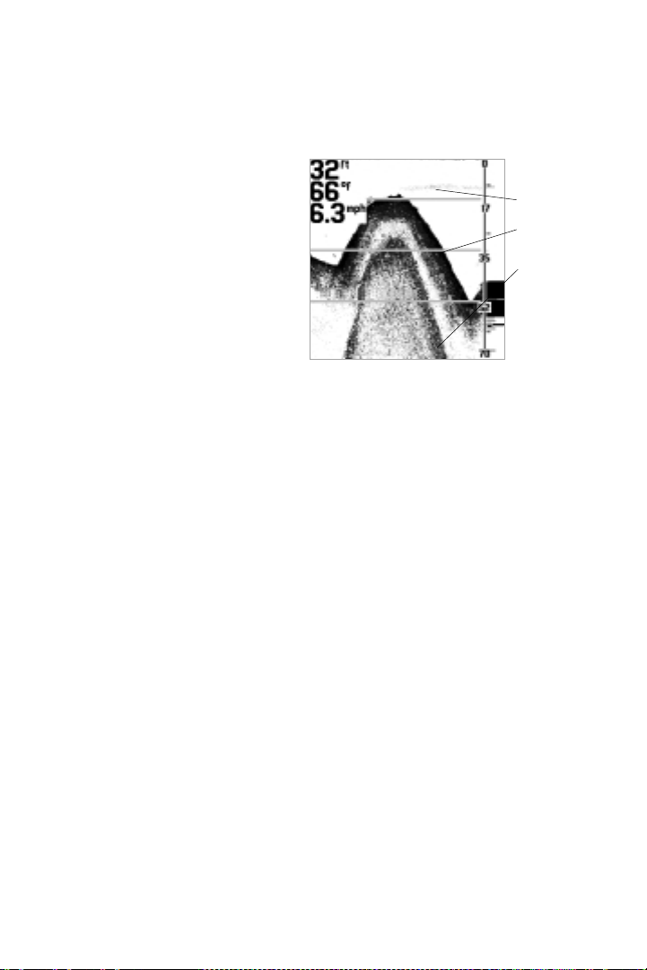
digital depth, temperature, speed and other readouts.
A digital depth readout ranging from 2 to 600 feet is alw ays displayed in
the upper left corner of the LCD. When the speed/temp accessory is
connected, additional digital readouts are show n below the depth. A
voltage readout appears in the bottom left w hen the input voltage to the
160 is less than 10 volts or greater than 16 volts.
USING THE 160
CONTROL FUNCTIONS
Depth Range
Scale
Depth, Temp and
Speed readouts
Real TIme Sonar
Window
Chart
Window

A depth range scale appears close to the right side of the LCD display. This
scale indicates the distance from the surface of the w ater to a depth range
sufficient to show the bottom. For example, in 18 feet of w ater a 20 foot
depth range is selected. The depth range scale can be controlled
automatically or manually depending on the mode of operation. In
automatic and bottom lock mode, the 160 selects the depth range. In
manual mode the depth range is selected by the user.
The sonar returns received by the 160 are displayed along the depth range
scale in a Real Time Sonar (RTS) Window and Chart Window. The RTS
Window displays new sonar information w ithin the transducer cone in an
expanded easy to see format; the Chart W indow logs old RTS W indow
information to show a contour view of the bottom and structure.
Real Time Sonar Window
The Real Time Sonar (RTS) w indow show s
instantaneous sonar returns from the
bottom, structure and fish that are within the
transducer beam. The RTS w indow updates
w it h new sonar inf ormation much more
quickly t han t he chart w indow - up to 20
times per second in shallow w ater. The RTS
w indow responds to quickly changing depths
similar to a flasher. Interpreting the RTS
information requires some skill; how ever
comparing the RTS presentation w ith the
information on the chart w indow makes it
easy to understand.
The RTS w indow plot s t he dept h and
intensity of a sonar return. Sonar intensity is indicated by the length of the
horizontal lines, w hile depth is indicated by the vertical placement of the
lines next to the depth range scale. The intensity of the sonar return is
divided into 4 levels of grayscale. The most intense returns are show n in
black; less intense sonar returns are show n in progressively lighter shades
of gray.
The combination of the length of the lines and the gray scale level helps to
identify the bottom composition and structure. The bottom is the largest
9
USING THE 160
CONTROL FUNCTIONS
Intense
returns
Less
intense
returns
Structure
Bottom

10
grouping of black horizontal lines, typically
having gray lines underneath. A harder
bottom show s less gray below ; a soft
bottom show s more gray below. St ructure
appears above the bottom as a cluster of
lines w ith varying lengths and gray shades.
Fish appear as smaller groupings of sonar
returns betw een the bottom and surf ace.
Often, large fish w ithin structure w ill
show as a strong return within a grouping
of smaller returns. When the boat is
stationary or drif ting very slow ly, t he RTS
w indow can show the movement of the fish through the transducer beam.
M oving fish appear as smaller groups of lines progressively become larger
lines, or vice versa. A grouping of lines moving vertically indicates a fish
changing depth.
The w idth of the RTS w indow can be adjusted to your preference.
Selecting a w ider RTS w indow show s greater differences betw een
the strength of the sonar returns; how ever it reduces the amount
of history on the display. See CONTROL PANELs for details of
adjusting the RTS Window.
The Chart Window
The chart w indow creates a hist orical log
of sonar returns from the RTS w indow. As
the boat moves, variations in the depth
and sonar return change and are charted
to form an image of the bottom contour.
The most recent sonar returns are charted
on the right side of t he w indow ; as new
information is received the older
information is moved across the display.
The chart w indow also indicates the
composition of the bottom. A hard bottom
such as compacted sediment or flat rock
appears as a dark, thin line across the
USING THE 160
CONTROL FUNCTIONS
Hard
Bottom
Fish
Soft
Bottom
Hard
Bottom
Soft
Bottom
Rocky
Bottom
Chart Window
11
display. Soft bottoms such as
mud or sand appear as a thicker
line having a transition from dark
to light grays. Bottoms made up
of many rocks have a broken,
random appearance.
Bottoms having a large degree
of slope also present a unique
picture. These generally have a
thicker black band representing
the bottom directly under the
boat. Equal areas of gray above and below the black band represent sonar
returns from around the boat.
A second sonar return may be visible if the appropriate depth range is
selected. This appears as a depth contour below the main bottom contour,
at tw ice the depth. The second return occurs w hen the sonar signal bounces
betw een the bottom and surface of the water and back again. Some anglers
use the appearance of the second return to determine bottom hardness.
With a low er gain setting the second return w ill be more faint, except in
areas w ith hard bottom . The 160 has a unique depth range feature w hich
permits the second return to be visible in any depth range. See M odes of
Operation for details.
The 160 displays structure such as submerged grass, brush, trees and w recks
on the bottom. Structure can be distinguished by comparing the area just
above and below the main bottom return. Usually structure show s as areas
of dark to light gray on top of a dark bottom contour. The appearance of
structure is greatly affected by boat speed and direction; to repeat the same
image it is often necessary to travel the same speed and direction over the
location w here the structure w as originally located.
The 160 is also capable of showing layers of w ater having different
temperatures. These temperature differences, called thermoclines, appear at
different depths, depending on current conditions. A thermocline typically
appears as a continuous band of many gray levels moving across the display
at the same depth. Thermoclines alw ays appear above the bottom.
Schools of bait fish as w ell as individual fish are clearly visible on the 160
display. Bait fish appear as " clouds" having different shapes and sizes
USING THE 160
CONTROL FUNCTIONS
Thermocline
Slope
Second
Return

12
depending on the number of fish
and boat speed. Individual fish
appear as smaller black and gray
lines often appearing as a " fish
arch." A fish arch forms as the fish
moves through the sonar beam.
Due to the transducer beam angle
the distance to the fish decreases
as it moves into the beam, and
then increases as it moves out.
When the chart w indow graphs
this distance change, an arch appears. Boat
speed, the Chart Speed setting and
movement of the fish greatly affect the
shape of t he arch. W hen moving slow ly, a
fish creates an elongated arch. With the
boat moving fast the arch appears shorter.
A partial arch forms w hen the fish does not
move through the entire cone angle.
It is important to remember that sonar cannot distinguish betw een a fish
and some other object suspended in the w ater. Regardless of the object the
sonar detects, each has the possibility of being draw n as an arch.
M ODES OF OPERATION
Three modes of operation control the method the 160 uses to track the
bottom and select depth ranges. The M ode
is selected by changing the CONTROL PANEL
setting to AUTO, M ANUAL, or BTM LOCK
(Bottom Lock).
AUTOM ATIC MODE
Autom atic M ode f ollow s t he bott om cont our, changing depth ranges as
needed to keep the most recent sonar returns visible on the display.
Automatic M ode keeps the bottom visible at all times, show ing sonar
returns from the surface to the bottom and just beyond. This is useful w hen
traveling across the w ater in areas w here the depth constantly changes
requiring frequent range changes.
USING THE 160
MODES OF OPERATION
Bait fish
Fish Arch
Partial Fish
Arch
Structure
Fish Arch Diagram

USING THE 160
MODES OF OPERATION
13
The 160 selects the depth range best
suited to keep recent sonar returns
visible, how ever, the depth range can be
adjusted to optimize the display for
viewing the second return. The display
can also be optimized for maximum
display resolution, making it possible to
distinguish fish very close together or
close to the bottom.
When the image of the bottom does not
appear close to the bottom of the LCD
display, the 160 is not fully optimizing
the display to show sonar targets, such as
fish, that are very close together. To
enhance the 160’s ability to separate sonar targets and optimize the display
for maximum resolution follow these steps.
1. M ake sure the 160 is operating in Automatic M ode.
2. Push the Range± Knob. An adjust ment indicator appears at the low er
right corner of t he chart w indow.
3. Turn the Range± Knob counterclockw ise until the image of bottom is
close to the bottom of the LCD display but still show s the area you are
interested in.
Note: As the depth of the w ater increases, the 160 changes the
depth range to keep the bottom on-screen. The 160 uses a depth
range to keep the bottom contour close to the bottom of the
display.
To return the depth range to normal view ing,
turn the unit ‘Off and back On again’. This is
the only w ay to ‘reset’ the depth range to
normal view ing.
To optimize the depth range for view ing the
second return follow these steps.
1. M ake sure the 160 is operating in
Automatic.
Adjustment Indicator
Optimized Display

2. Push the Range± Knob. An adjustment
indicator appears at the low er right corner
of the chart w indow.
3. Turn t he Range± Knob clockw ise until
the second return is visible on the display.
4. To return the depth range to normal
view ing, rotate t he dept h range
counterclockw ise unt il t he depth range
stops updating.
Note: The second return does not
appear at many of the deeper depth
ranges. The appearance of the second return depends on depth of
the w ater, w ater conditions, bottom hardness and the gain
setting.
The 160 operates w ith this offset depth range until it is returned to the
original settings or the unit is turned off.
BOTTOM LOCK ZOOM MODE
Bot tom Lock M ode tracks t he bottom similar to
Automatic M ode, how ever the display show s a full range view on right and
a zoomed window on the left. The zoomed w indow provides added display
resolution for separating sonar returns that are very close together, such as
fish suspended close to the bottom.
As the depth changes the 160 automatically keeps the bottom visible in the
zoomed w indow and the full range view. In the full range view, horizontal
zoom preview bars define the area of bottom being enlarged. The default
setting varies based on the depth range. How ever, this setting can be
changed to show more area around the bottom, or the bottom in greater
detail.
To change the area of the bottom being zoomed, follow these steps:
1. M ake sure the 160 is operating in Bottom Lock mode.
2. Push t he Range± Knob. An adjust ment indicator appears by t he low er
zoom preview bar indicating this is the selected depth limit for adjustment.
14
Opt imized Display show ing
second return
USING THE 160
MODES OF OPERATION

15
Note: Pushing the R
ANGE
±K
NOB
toggles betw een the upper and
low er zoom preview bar adjust-
ment. If the low er zoom preview
bar is to be adjusted, push the
Range±Knob until it is selected.
3. Rotate the Range Knob to adjust the
zoom preview bar. M oving the zoom
preview bars closer together increases the
display resolut ion in t he zoom ed w indow ;
moving them further apart decreases display
resolution, but allow s more area around the
bottom t o be view ed.
The indicators disappear after several seconds w ith no adjustment. The 160
continues to follow the bottom using the new range. Any change made to
the zoom preview bars is remembered until the 160 is pow ered off.
MANUAL MODE
M anual M ode turns off the automatic bottom
tracking leaving control of the depth range to the
user. Both the upper and lower depth ranges can be adjusted to show the
bottom in great detail or any other desired depth. When first sw itched to
manual mode, the 160 defaults to the current automatic depth range;
however, after the manual depth ranges have been set, the 160 uses the
new sett ings until it is pow ered off.
M anual M ode w orks best in areas of relatively flat bottom or if you are
trolling slow ly. It is also ideal for displaying a small area of the overall depth
range in great detail if you are looking for fish at a specific depth.
To manually adjust the depth ranges follow these steps:
1. M ake sure the 160 is operating in M anual M ode.
2. Push the Range Knob. An adjustment indicator appears at the location
of the lower Depth Range indicating it is ready for adjustment.
15
USING THE 160
MODES OF OPERATION
Bottom Lock Zoom M ode
Zoom
Window
Zoom Preview
Bars

16
Note: Pushing the Range
Knob toggles betw een the
upper and low er depth
range selection. If the upper
Depth Range is to be
adjusted, push the Range
Knob until it is highlighted.
3. Rotate the Range Knob to adjust the
Depth Range. Clockw ise rotation
increases t he dept h; count erclockw ise
rotation decreases the depth. The display
updates as the changes are made.
Af ter several seconds w ithout pressing or
turning the knob the depth range
adjustment indicator disappears from the
screen. The 160 does not make
adjustments to keep the bottom
information on-screen. If the depth is
deeper or shallower than the ranges on
the display, t he bot tom contour w ill not
be visible.
The manual range settings made to the
160 are remembered until the unit is
turned off.
CONTROL PANELS
CONTROL PANELs provide access to important,
but infrequently adjusted features, such as
Chart Speed, M ode, Light, Contrast, RTS
Window, Surface Clutter, White Line,
Depth Alarm, Units, Simulator, Language.
16
USING THE 160
CONTROL PANELS
M anual M ode
Upper Depth Range
Adjustment Indicator
Low er Dept h Range
Adjustment Indicator

Note: The Language and Units menus only appears on special
international versions of the 160.
CONTROL PANELS are displayed by using
the CONTROL PANEL knob and adjusted by
using the Range knob. The active
CONTROL PANEL consists of three parts:
The CONTROL PANEL Name indicates the
feature, the Sett ing Indicator show s the current
setting within the complete range of adjustment,
and t he Set ting Readout show s the status w hen
CONTROL PANEL is not selected.
To select a CONTROL PANEL for adjustment follow
these steps:
1. Press the CONTROL PANEL knob. A list of options appears on the display.
The option currently selected for adjustment is indicated by a w hite
background color.
2. Rotate the CONTROL PANEL knob to select the
desired option for adjustment. Clockw ise
rotation selects options higher in the list;
counterclockw ise rotation selects options low er
in the list.
Note: Not all options in the list can be
view ed on the display at one time. When
the selected option is at the bottom of the
list, continue turning the knob to display
other options.
3. Once the desired option is selected, turn the Range knob to adjust.
Adjustments are made immediately and are show n by an indicator on the
selected CONTROL PANEL.
4. Remove the CONTROL PANELs by pushing the CONTROL PANEL knob. Or, after
a few seconds with no knob press/turn the CONTROL PANELs automatically are
removed from the display.
Setting
Indicator
1717
USING THE 160
CONTROL PANELS
Active
Control
Panel
CONTROL PANEL
Name
Setting
Readout

18
CHART SPEED selects the speed at w hich the
bottom information moves across the display.
Opt ions available range f rom 1 (very slow ) t o eight
(very fast). Selecting a faster rate show s more
information in the chart w indow ; how ever it
moves across the display very quickly. Selecting a slow er rate keeps the
information on the display longer, but the chart information becomes
compressed and may be more difficult to interpret. Setting Chart Speed in
proportion to boat speed is often preferred.
The Chart Speed setting is retained in memory w hen the 160 is turned off.
The factory setting is 6.
MODE selects how the 160 locates the bottom
and graphs the information on the display. Refer
to page 12 for a description of the M odes of
Operation.
LIGHT activates the display back light and selects
the brightness level. The light is manually
controlled except w hen the 160 f irst pow ers up.
During start up, the back light turns on at full
brightness so the display will be visible at night. However, the back light
automatically decreases in intensity until it is off. Selecting the CONTROL
PANEL during the automatic off process keeps the back light on at the last
intensity level.
Light setting is not retained in memory when the 160 is turned off.
CONTRAST enhances the view ability of the LCD by
making it darker or lighter. Selecting a higher
number darkens t he display; selecting a low er
number lightens the display. The 160 uses
sophisticated electronics to automatically adjust the contrast level; how ever
at times of extreme heat or cold manually adjusting the contrast for best
display may be needed.
The Contrast setting is retained in memory if it falls betw een 6 and 10. The
factory setting is 8.
18
USING THE 160
CONTROL PANELS
Other manuals for TFX160
1
Table of contents
Other Teleflex Marine Equipment manuals


