Sonardyne DPT6 User manual

QUICK START GUIDE
DPT6 C6
BATTERY REPLACEMENT
/ /AMT6 TRANSPONDERS
To access more information
on the transponders battery
change, download a free
QR code app on your
Smartphone and then scan
this code.
QSG-BR-8300-00-A1
04/2013
910-0002

SAFETY
High pressure hazard risk when dismantling sub-sea equipment. Dismantling must only be
carried out by trained personnel.
Electric shock hazard risk when dismantling the equipment. Dismantling must only be carried
out by trained personnel.
Make sure the Pressure Relief Vent Valve is manually operated, in a well ventilated area, to
release any internal pressure before attempting to remove the end-cap.
Risk of burns. Do not change the battery pack if the housing is hot. Lower the transponder
overboard and wait for the housing to cool. Wear Personal Protective Equipment such as gloves.
Risk of impact injury. Do not stand in-line with the end-cap when removing from the
transponder.
Make sure the equipment is dry before dismantling.
Do not fit unauthorised battery pack types into an instrument.
For Lithium and Lithium Ion battery packs, Class D fire extinguishers should be used. Do not use
any other type of extinguisher.
The 8300 series of transponders weigh between 35 and 23 kg. Manual handling Equipment
(MHE) must be used to move the transponders. If MHE is not available, then a manual handling
assessment must be carried out prior to carrying out manual lifting / handling. Personal
Protective Equipment such as protective footwear and gloves must be worn before lifting the
equipment.
WARNINGS
STEP 1
It is recommended the operator complies with the Health and Safety Regulations applicable to the vessel and the
region before operating this equipment.
If the equipment is used in a manner not specified by the manufacturer, the protection provided by the
equipment may be impaired.
Documentation must be consulted whenever the warning symbol is found on the equipment, in order to find
out the nature of the potential hazard and any actions which must be taken.
The batteries used in the 8300 transponders can be lithium based. Due to the high risks associated with these
types of batteries, it is important that the safety instructions in this Quick Start Guide are read and fully
understood.
Only trained and qualified personnel must carry out the battery replacement procedure detailed in this Quick
Start Guide.
Do not expose batteries to extreme temperatures, in excess of 60°C, to prevent reduction in
battery life.
CAUTION
PRODUCT SUPPORT
Email: [email protected]
Tel: +44 (0) 1252 872288
Should you require NON-EMERGENCY product support for your transponder, email and telephone product
support is available during normal UK office hours (08:00-17:00). Alternatively, please contact your nearest
Sonardyne Office. Visit www.sonardyne.com for full details.
In emergency situations, the Sonardyne 24 hour helpline is answered during normal office hours - 08:00-17:00.
Outside these hours, your call is automatically transferred to an agency who will log the details of your
emergency and alert the appropriate Sonardyne personnel. Our aim is to ensure that emergency requests are
dealt with immediately during office hours and are responded to within 30 minutes at all other times.
SONARDYNE 24HR EMERGENCY HELPLINE: UK +44 (0) 1252 877600

STEP 2
PREPARING THE EQUIPMENT
1 Make sure the equipment has been rinsed in clean fresh water.
2 Remove any excess marine growth.
3 Dry the transponder with clean lint free cloth.
4 Inspect the transponder for any signs of damage, temperature.
5 If the transponder body is hot, lower into cold water to cool. When the body has
cooled, dry with clean lint free cloth.
6 Move the transponder to a clean dry environment.
7 Inspect the transponder around the Pressure Relief Vent Valve for deposits. This
would indicate the battery has vented due to water ingress or electronics/battery
malfunction. In these circumstances the battery pack and internal electronics may
have been severely damaged.
Risk of burns. Do not carry out any maintenance if the transponder housing is
hot. Lower the transponder overboard and wait for the housing to cool.
High pressure hazard risk when dismantling sub-sea equipment. Dismantling
must only be carried out by trained personnel.
Heavy Equipment. The type 8300 series of transponders weigh between 35 and
23 kg. Manual handling Equipment (MHE) must be used to move the
transponders. If MHE is not available, then a manual handling assessment must
be carried out prior to carrying out manual lifting / handling. Personal
Protective Equipment such as protective footwear and gloves must be worn
before lifting the equipment.
WARNINGS
This Quick Start Guide gives instructions on how to replace the battery in the 8300 series
transponders.
Before carrying out any activity on the equipment, make sure all Warnings and
Caution labels on the equipment and within this Quick Start Guide are read and
understood. Refer to the equipment manual for further information and assistance.
Before attempting to dismantle the transponder to replace the battery, the transponder
must be cleaned and thoroughly dried.
Use the following procedure to prepare the equipment.

STEP 3
DISMANTLING THE EQUIPMENT
High pressure hazard risk when dismantling the sub-sea equipment, refer to
the Safety Section. Must only be carried out by trained personnel.
Make sure the Pressure Relief Vent Valve is operated in a well vented area, to
remove any risk of internal pressure build up.
Heavy Equipment. The type 8300 series of transponders weigh between 35 and
23 kg. Manual handling Equipment (MHE) must be used to move the
transponders. If MHE is not available, then a manual handling assessment must
be carried out prior to carrying out manual lifting / handling. Personal
Protective Equipment such as protective footwear and gloves must be worn
before lifting the equipment.
WARNINGS
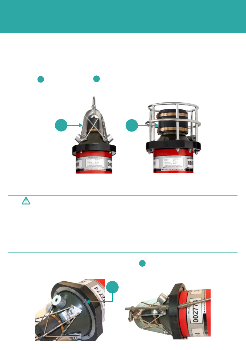
1 Clean the area around the Pressure Relief Vent Valve , make sure any marine
growth is removed.
2 Check the Pressure Relief Vent Valve is flush with the housing.
1
1
Use the following procedure to dismantle the equipment and remove the battery.
1
2
3
4
3 Screw an M4 screw ( not supplied) into the Pressure Relief Vent Valve plug.
4 Slowly pull out the Pressure Relief Vent Valve to release any internal pressure,
and reveal the two O-rings . A pair of long nose pliers can be used to assist.
5 Wait for any internal pressure to be fully vented from the housing.
6 Inspect the O-rings , for signs of damage. Apply a light coating of petroleum jelly
to lubricate the O-rings .
7 Release the Pressure Relief Vent Valve and allow it to reseat. Apply a little
pressure to make sure it is flush with the end-cap.
2
3
4
2
4
2
4
STEP 4
DISMANTLING THE EQUIPMENT
There are two types of transducer end-caps that can be fitted to the equipment: an omni-
directional , and a directional . For instructions on removing the directional end-cap
refer to Step 6.
12
1
2
REMOVING THE TRANSCEIVER END-CAPS
REMOVING THE OMNI-DIRECTIONAL TRANSDUCER END-CAP
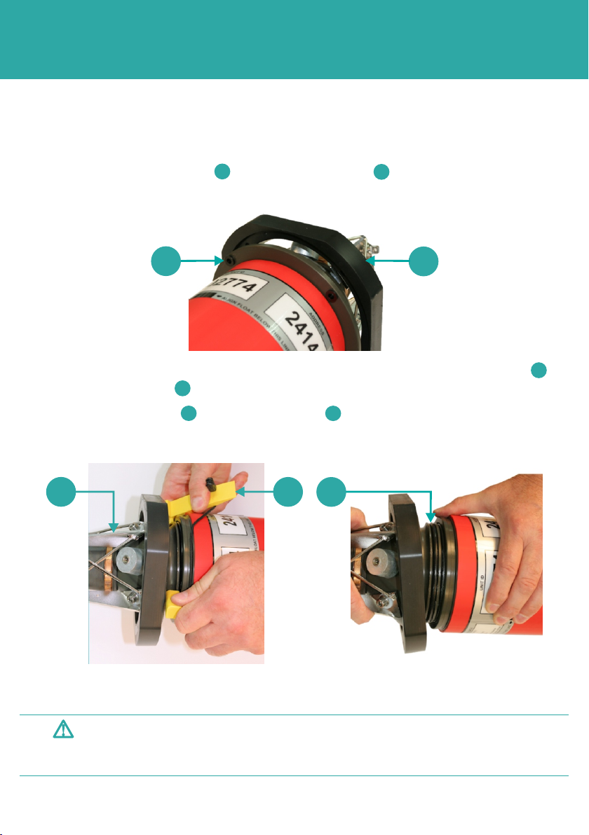
1 Undo and remove the nuts, washers and bolts securing the clamp rings.
1
1
Do not stand in directly in-line with the end-cap when removing it from the
transponder housing.
Do not remove the end-cap if there is a gap between the end-cap and the
housing body. Refer to the User Manual for instructions.
Do not continue to remove the end-cap if movement is felt during removal
of the clamp rings. Refer to the equipment User Manual for assistance.
WARNINGS
STEP 5
DISMANTLING THE EQUIPMENT
REMOVING THE OMNI-DIRECTIONAL END-CAP
2 Push the rubber bump stop free of the clamp rings and housing.
1
2
4
35
5 Use a lint free cloth to clean around the O-ring seals.
Remove the end-cap slowly to prevent the transducer cable becoming
detached.
CAUTION
6 Remove the end-cap completely.
2
1
3 Remove any dirt or water that may have accumulated between the rubber stop
and the clamp rings .
4 Use the opening tool to lever the end-cap from the housing until the O-ring
seals are exposed.
2
43
1
STEP 6
DISMANTLING THE EQUIPMENT
REMOVING A DIRECTIONAL END-CAP
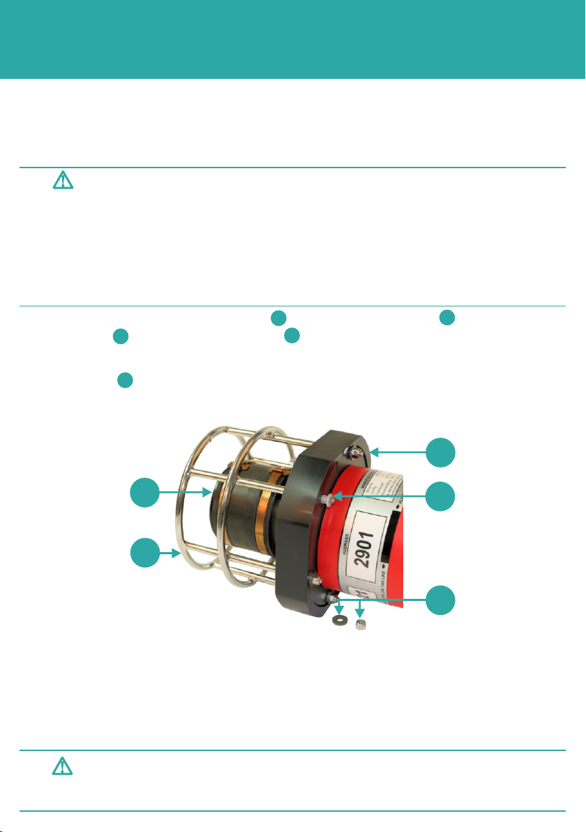
3 With the guard and bump stop removed, remove the clamp rings.
4 Remove any dirt, silt or water that may have accumulated around the end-cap.
5 Using the Opening Tools, lever the transducer end-cap from the housing until the
O-ring seals are exposed. Use a lint free cloth to clean around the O-ring seals.
1
2
3
4
5
1 Undo and remove the nuts, washers and white nylon spacers from the end of
the guard protecting the transducer .
2 Lift the end of the transducer housing sufficiently to allow the protective guard and
bump stop to be removed from the clamp rings.
12
3
4
5
Remove the transducer end-cap slowly to prevent the transducer cable
becoming detached.
CAUTION
Do not stand in directly in-line with the end-cap when removing it from the
transponder.
Do not remove the end-cap if there is a gap between the end-cap and the
housing body. Refer to the User Manual for instructions.
Do not continue to remove the end-cap if movement is felt during removal
of the clamp rings. Refer to the equipment User Manual for assistance.
WARNINGS

STEP 7
DISMANTLING THE EQUIPMENT
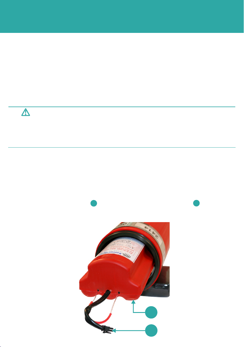
REMOVING THE BATTERY
Make sure the transducer is removed from the housing. Proceed with removing the battery
as follows:
Make sure the equipment is dry before dismantling.
Electric shock hazard risk when dismantling the equipment. Dismantling
must only be carried out by trained personnel.
For Lithium and Lithium Ion battery packs, Class D fire extinguishers should
be used. Do not use any other type of extinguishers.
WARNINGS
Do not expose batteries to extreme temperatures, in excess of 60°C, to prevent reduction in
battery life.
CAUTION
2
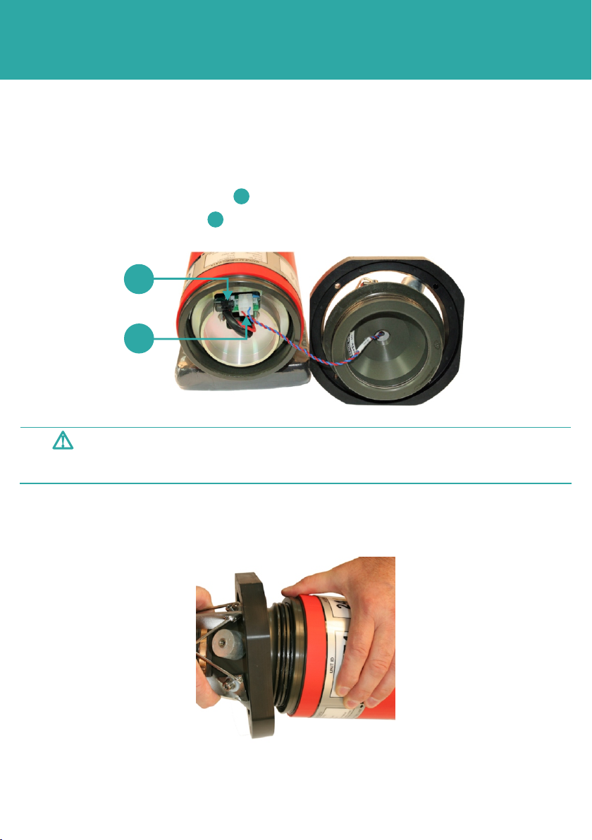
1 Disconnect the battery connector .
2 Disconnect the transducer connector .
1
1
2
3 Pull out the top bulk head .
3
3
STEP 8
DISMANTLING THE EQUIPMENT
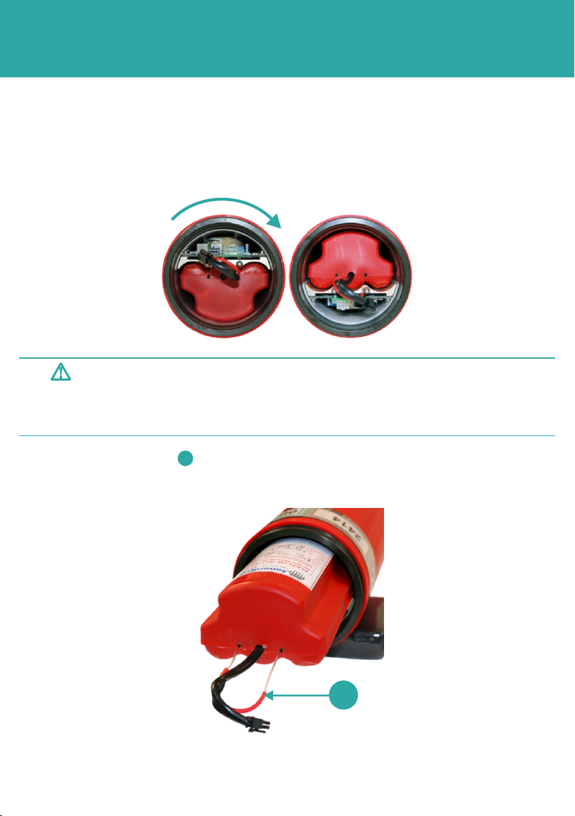
6 The battery pack is now fully removed from the transponder.
7 Refer to Step 14 for instructions on disposal or transportation of the batteries.
Risk of burns. If the battery pack has been exposed to flooding, personal
protective equipment, such as gloves, must be worn to handle the battery
pack.
WARNING
4 Rotate the transponder so the battery is upper most in the housing.
5 Using the draw-string , slowly pull and support the battery pack out of the
transponder.
1
1
REMOVING THE BATTERY
STEP 9
CONNECTING THE EQUIPMENT
Electric shock hazard risk when assembling the equipment. Assembly must only
be carried out by trained personnel.
Make sure the equipment is dry before assembly.
Do not fit unauthorised battery pack types into an instrument.
WARNINGS
Before inserting a new battery pack into the transponder housing, inspect the housing for
any signs of damage or corrosion. Refer to the manual for assistance if necessary.
Make sure all Warnings and Cautions in the Safety section have been read and fully
understood.
1 Make sure the correct type of battery is available.
2 If installing a new battery remove any packaging.
3 Make sure the transponder is positioned so the battery pack would be located on
top of the circuitry.
4 Inspect the new battery for any signs of damage.
5 With the battery connector facing outwards, support the battery and slide it
into the transponder housing.
21
1
2
FITTING THE BATTERY

STEP 10
CONNECTING THE EQUIPMENT
7 Position the top bulk head over the two locating pins and firmly push into position.
8 Inspect the end-cap for any signs of damage or corrosion, pay particular attention to
the O-ring groove.
9 Inspect the O-ring seals for signs of damage. Replace if necessary.
10 Lubricate the O-ring seals with petroleum jelly.
1
2
6 Push the battery connector through the top bulk head .
12
FITTING THE BATTERY
STEP 11
CONNECTING THE EQUIPMENT
14 Coil the cable inside the bulk head and push the transducer into the housing. Make
sure the cable does not become trapped.
Observe the position of the transducer cable; be careful not to trap the cable
when inserting the transducer.
CAUTION
11 Position the end-cap next to the transponder housing.
12 Connect the transceiver cable .
13 Connect the battery pack .
2
1
FITTING THE BATTERY
1
2
15 If the transceiver end-cap is an omni-directional type proceed to fitment instructions.
If the transducer end-cap is a directional type, refer to Step 13 for installation
instructions.

STEP 12
CONNECTING THE EQUIPMENT
4 Secure the clamp rings to the bumper stop using the bolts, washers and nuts.
5 Tighten the nuts and bolts.
1 Push the omni-directional transceiver end-cap fully into the housing. Make sure the O-
ring seals do not become damaged.
2 Position the clamp rings in the grooves on the end cap.
3 Slide the rubber bumper stop over the end cap and align with the holes in the
clamp rings .
2
1
FITTING THE OMNI-DIRECTIONAL TRANSDUCER END-CAP
1
4
2
1
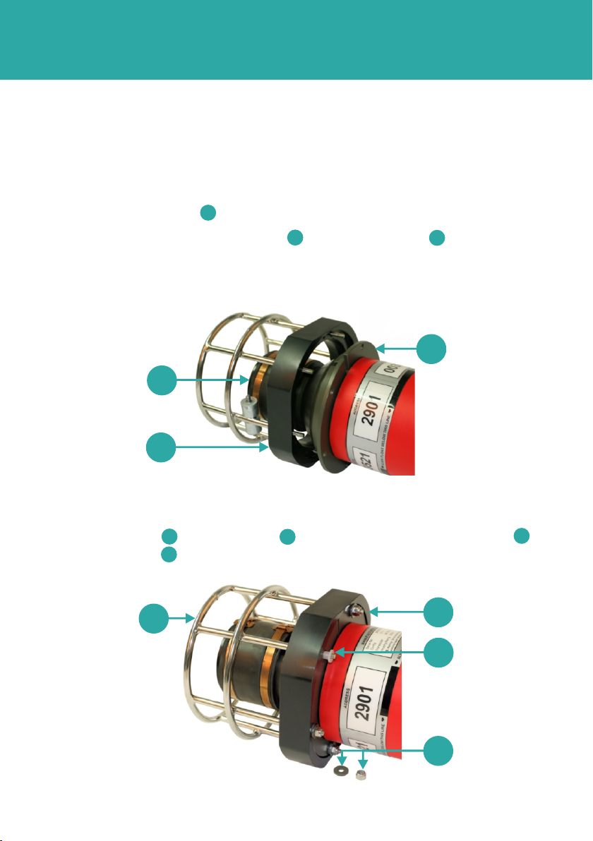
STEP 13
CONNECTING THE EQUIPMENT
FITTING THE DIRECTIONAL TRANSDUCER END-CAP
7 The transponder is now ready for operation.
45
6
7
1 Push the directional transducer end-cap fully into the housing. Make sure the O-ring
seals do not become damaged.
2 Position the clamp rings in the grooves on the end cap.
3 Position the guard with the bump stop over the transducer .
4 Rotate the clamp rings, if necessary, to align the holes with the screw ends of the
guard.
12
3
5 Lift the end of the transponder housing enough to locate the guard screws through
the holes in the clamp rings.
6 Secure the guard and bump stop in place with the six nylon spacers ,
washers and nuts .
456
7
1
2
3

DISPOSAL OR TRANSPORTATION
When disposing of all lithium based batteries please refer to the regulations of the local
area. Do not dispose of lithium or lithium ion batteries in a fire or incinerator.
STEP 14
Risk of explosion. Do not dispose of lithium or lithium Ion batteries in a fire.
WARNING
DISPOSAL OF LITHIUM BASED BATTERIES
TRANSPORTATION OF LITHIUM BASED BATTERIES
When transporting lithium based batteries manufacturer’s material safety datasheet must
be read to confirm the amount of lithium per battery pack. These quantities cannot be
verified by Sonardyne International Ltd.
It is the operator’s responsibility to obey local, national and international regulations in
force at the time of transport.
By Road: ADR European Agreement concerning the International Carriage of Dangerous
Goods by Road Regulations.
By Sea: International Maritime Dangerous Goods Code.
By Air: IATA Regulations UN 3090 and UN 3091

Global Headquarters, UK
T. +44 (0) 1252 872288
F. +44 (0) 1252 876100
Houston, USA
T. +1 281 890 2120
F. +1 281 890 7047
24/7 Emergency Hotline
+44 (0) 1252 877600
Email Support
Website
www.sonardyne.com
Twitter
@sonardyne
Aberdeen, UK
T. +44 (0) 1224 707875
F. +44 (0) 1224 707876
Singapore, Asia
T. +65 6542 1911
F. +65 6542 6937
QSG-BR-8300-00-A1
04/2013
910-0002
ACOUSTIC POSITIONING INERTIAL NAVIGATION
llWIRELESS COMMUNICATION lSONAR IMAGING
Rio das Ostras, Brazil
T. +55 22 2123 4950
F. +55 22 2123 4951
Other manuals for DPT6
1
This manual suits for next models
2
Table of contents
Other Sonardyne Marine Equipment manuals


