TELEMED UAB MicrUs Series User manual

MicrUs and MicrUs Pro Series Ultrasound Systems
Echo Wave A Software
User Manual
TELEMED
Medical Systems
Italy
UAB Telemed
Lithuania
www.telemedultrasound.com/?lang=en
_www.telemed.lt

TELEMED
Echo Wave A Software User Manual Ver. 1.2.1 2020.07.02 Page 2 of 25
Content
1.
Introduction ................................................................................................................................................................. 3
2.
System Startup and Shutdown ................................................................................................................................ 4
2.1.
System Startup ........................................................................................................................................................ 4
2.2.
System Shutdown ................................................................................................................................................ 4
3.
Software User Interface Structure .............................................................................................................................. 5
3.1.
Main Window ........................................................................................................................................................ 5
3.2.
Types of Controls .................................................................................................................................................... 6
4.
Typical Ultrasound Examination Workflow ............................................................................................................ 7
5.
Using Ultrasound Scanning Presets .......................................................................................................................... 8
6.
Patient Information ...................................................................................................................................................... 10
7.
Adjusting Ultrasound Image Quality ........................................................................................................................ 11
7.1.
Adjusting B Mode Controls .................................................................................................................................. 11
7.1.1.
Focus ........................................................................................................................................................... 11
7.1.2.
Depth ............................................................................................................................................................... 11
7.1.3.
Dynamic Range ......................................................................................................................................... 12
7.1.4.
Power .......................................................................................................................................................... 12
7.1.5.
Gain ................................................................................................................................................................. 13
7.1.6.
Change Scan Direction ................................................................................................................................ 13
7.1.7.
Frequency ................................................................................................................................................... 14
7.1.8.
Frame Averaging .......................................................................................................................................... 14
7.1.9.
Rejection ......................................................................................................................................................... 14
7.1.10.
Image Enhancement ............................................................................................................................... 15
7.1.11.
Speckle Reduction ..................................................................................................................................... 15
7.1.12.
Lines Density ............................................................................................................................................ 16
7.1.13.
Map ............................................................................................................................................................... 16
7.1.14.
Gamma, Brightness, Contrast ............................................................................................................... 16
7.1.15.
Negative .................................................................................................................................................... 17
7.1.16.
Zoom ............................................................................................................................................................. 17
7.1.17.
TGC (Time Gain Compensation) ............................................................................................................. 18
8.
Measurements and Calculations ........................................................................................................................... 19
8.1.
B Mode Measurements ........................................................................................................................................ 19
8.1.1.
Distance .......................................................................................................................................................... 19
8.1.2.
Area, Circumference and Volume using Ellipse .................................................................................... 19
8.2.
Deleting Performed Measurements ................................................................................................................... 20
9.
Saving and Loading Images and Cines ............................................................................................................... 21
10.
Options ................................................................................................................................................................... 22
11.
About ........................................................................................................................................................................... 24
12.
System Requirements .......................................................................................................................................... 25
13.
Troubleshooting ..................................................................................................................................................... 25
14.
References ................................................................................................................................................................. 25
15.
Revision History ........................................................................................................................................................ 25

TELEMED
Echo Wave A Software User Manual Ver. 1.2.1 2020.07.02 Page 3 of 25
1. Introduction
This document ("MicrUs and MicrUs Pro Series Ultrasound Systems Echo Wave A Software User
Manual") describes the TELEMED Ultrasound Systems based on MicrUs or MicrUs Pro series of ultrasound
scanners and "Echo Wave A" ultrasound scanning software.
This document describes the "Echo Wave A" ultrasound software user interface, its structure,
controls and how to use this software for ultrasound processing. Please note that in this manual the software
screenshots shown may look slightly different from the actual software user interface because user interface
may depend on the used operating system adjustments.In this document to refer to "Echo Wave A"
ultrasound software may be used term “ultrasound software” or simply ”software”.
Before using this software, you must be trained in clinical procedures for conducting
ultrasound examinations. This guide does not provide guidelines for clinical aspects of performing
the examination or for interpreting medical ultrasound images.
In addition, before using this software you must be familiar with the use of Android 6.0 or
more recent operating system and mobile phone or tablet computer that has installed this operating
system.

TELEMED
Echo Wave A Software User Manual Ver. 1.2.1 2020.07.02 Page 4 of 25
2. System Startup and Shutdown
2.1.System Startup
If the system was properly installed and connected, perform the following actions to start the system:
1.
If required, power up mobile phone or tablet computer and unlock the screen.
2.
Click “Echo Wave A” icon. The icon may be not on first, but on second or other page (or on one of
the pages of installed applications), so you may need to sweep through pages to find it.
3.
After click you should see ultrasound software user interface.
2.2.System Shutdown
To exit "Echo Wave A" software, click “Back” button of the operating system or phone/tablet and,
when asked if you want to close software, click “Yes”.

TELEMED
Echo Wave A Software User Manual Ver. 1.2.1 2020.07.02 Page 5 of 25
3. Software User Interface Structure
3.1.Main Window
1 2
10
3
4
5
11
6
12
7
8
9
13
Num
Description
1
Scan direction marker that indicates at what side is first probe element.
2
Remaining phone battery indicator.
3
Zero depth (probe surface) tick mark.
4
Depth scale line.
5
TGC (Time Gain Compensation) curve.

TELEMED
Echo Wave A Software User Manual Ver. 1.2.1 2020.07.02 Page 6 of 25
6
Focusing depth marker.
7
Actual scanning depth (numerical value in millimeters).
8
Buttons to record cine, save image, freeze/run, open settings (presets, options), measure
distance, measure area (using ellipse), delete measurements.
9
Ultrasound scanning controls (Gain, Power, Depth and others). This area can be scrolled
up/down.
10
Ultrasound scanning frame rate (FPS - frames per second).
11
Scanned ultrasound image.
12
The name of connected probe.
13
Phone “Back” button.
3.2.Types of Controls
This section describes software controls that may slightly differ from standard Android controls and
that require some knowledge where and how to touch the screen in order to get desired result.
To change value of some ultrasound scanning parameter (like Gain, Power, Depth), while ultrasound
scanning is running must be clicked corresponding button (then is turned on parameter change mode and
changed button color) and then done horizontal or vertical sweeps on ultrasound image. After
some time of inactivity, parameter change mode is turned off and button color is restored .
While parameter change mode is turned on, the same button can be clicked once again to turn change mode
off.
Depending on scanning parameter, the value may be changed either continuously during movement
(sweep) action (e.g., Gain value) or only when finger is released (e.g., Depth value). Required mouse
movement type can be determined by observing hint image (“|” or “:”) at the right of parameter name. For
different scanning parameters are used different controls because different parameters have different
number of values and require different time for programming of ultrasound scanning hardware. For example,
the change of depth value requires much more time than the change of gain value.
If button does not have above mentioned hint image, this means that button action will be performed
after usual click and does not require additional mouse actions on the ultrasound image.
Some software parameters may be controlled by doing actions with finger(s) on the ultrasound
image while buttons of scanning parameters are not active. For example, vertical press-move-release
actions along B mode vertical scale line adjust B mode focusing depth. Press and hold on B mode image at
any vertical position that is at the right of depth scale line will show the TGC curve, and then horizontal
press-move-release actions will change TGC values at desired depths. Pinch operation with two fingers
zooms in/out ultrasound image, sweep on zoomed image changes its position, and single click on zoomed
image restores zoom to 100%. How to adjust each ultrasound scanning parameter and how it affects
ultrasound image quality is described in other sections of this document.

TELEMED
Echo Wave A Software User Manual Ver. 1.2.1 2020.07.02 Page 7 of 25
4. Typical Ultrasound Examination Workflow
To perform ultrasound examination, start software and follow these steps:
1.
Click Freeze/Run button to freeze/run ultrasound scanning and clear all measurements.
2.
If required, enter patient identifier (ID). To do this, click “Settings” button , then “Patient” tab, enter ID,
close opened window by clicking phone “Back” button.
3.
Adjust ultrasound image quality using ultrasound scanning controls.
4.
Use proper medical protocols to perform the ultrasound examination.
5.
Click "Freeze/Run" button to freeze the ultrasound image currently displayed.
6.
Perform any measurements and calculations if required.
7.
Save ultrasound image.
8.
Press the "Freeze/Run" button to restart the ultrasound scanning. Ultrasound scanning freeze/run
state is indicated by the color of button and scan direction marker. While scanning, colors are as follows:
. When scanning is stopped, colors are as follows: .
9.
Optionally, repeat steps 1-8 to scan more ultrasound images.
Detailed information how to adjust ultrasound scanning parameters, do measurements and other
operations will be provided in next sections.
Note. To change ultrasound probe, click "Freeze/Run" button to freeze ultrasound scanning,
change probe, click "Freeze/Run" button to initialize connected probe and start scanning (for
MicrUs Pro initialization and scanning start are done automatically). Also you can close software,
change probe, start software.
TELEMED
Echo Wave A Software User Manual Ver. 1.2.1 2020.07.02 Page 8 of 25
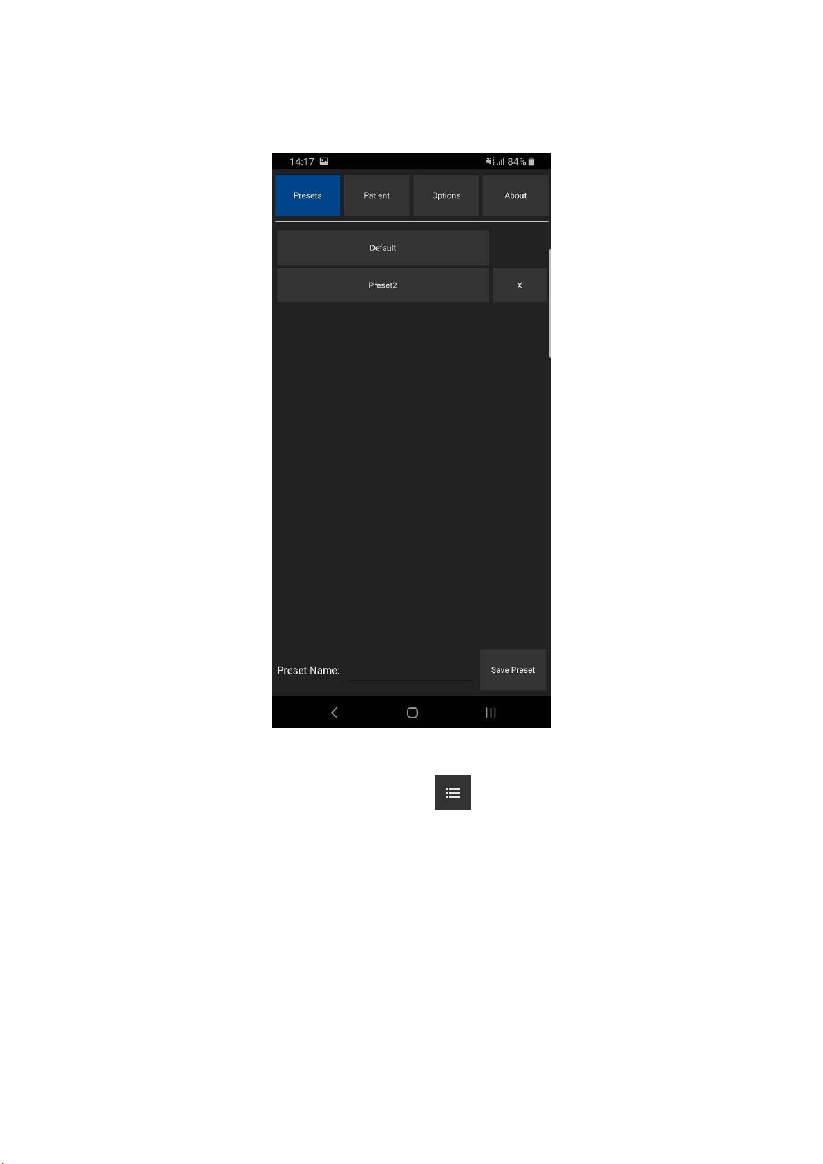
5. Using Ultrasound Scanning Presets
In order to apply ultrasound scanning preset, unfreeze ultrasound scanning (if now it is frozen) by
clicking “Freeze/Run” button and perform the following actions:
1.
Open the presets list by clicking on the "Settings" button , then “Presets” tab.
2.
In the appeared list click on preset name in order to apply it. If the number of available presets is large,
presets list can be scrolled by doing vertical sweeps with finger over opened presets list.
3.
Optionally, repeat steps 1-2 to use another preset.

TELEMED
Echo Wave A Software User Manual Ver. 1.2.1 2020.07.02 Page 9 of 25
To save current ultrasound scanning parameters as preset for future use, please perform the
following actions:
1.
Open the presets list by clicking on the "Settings" button and “Presets” tab.
2.
Click text field at the right of “Preset Name:” text, enter preset name using on-screen keyboard and click
“Save Preset” button. Presets are saved to folder "Internal Storage>Documents>EchoWaveA>Presets".
To delete ultrasound scanning preset, please perform the following actions:
1.
Open the presets list by clicking on the "Settings" button and then “Presets” tab.
2.
Click preset deletion button
3.
Click “Yes” when asked if you want to delete preset.
Please note that some presets are protected, and you may not be able to delete them (deletion
button is not shown).
at the right of its name.
TELEMED
Echo Wave A Software User Manual Ver. 1.2.1 2020.07.02 Page 10 of 25
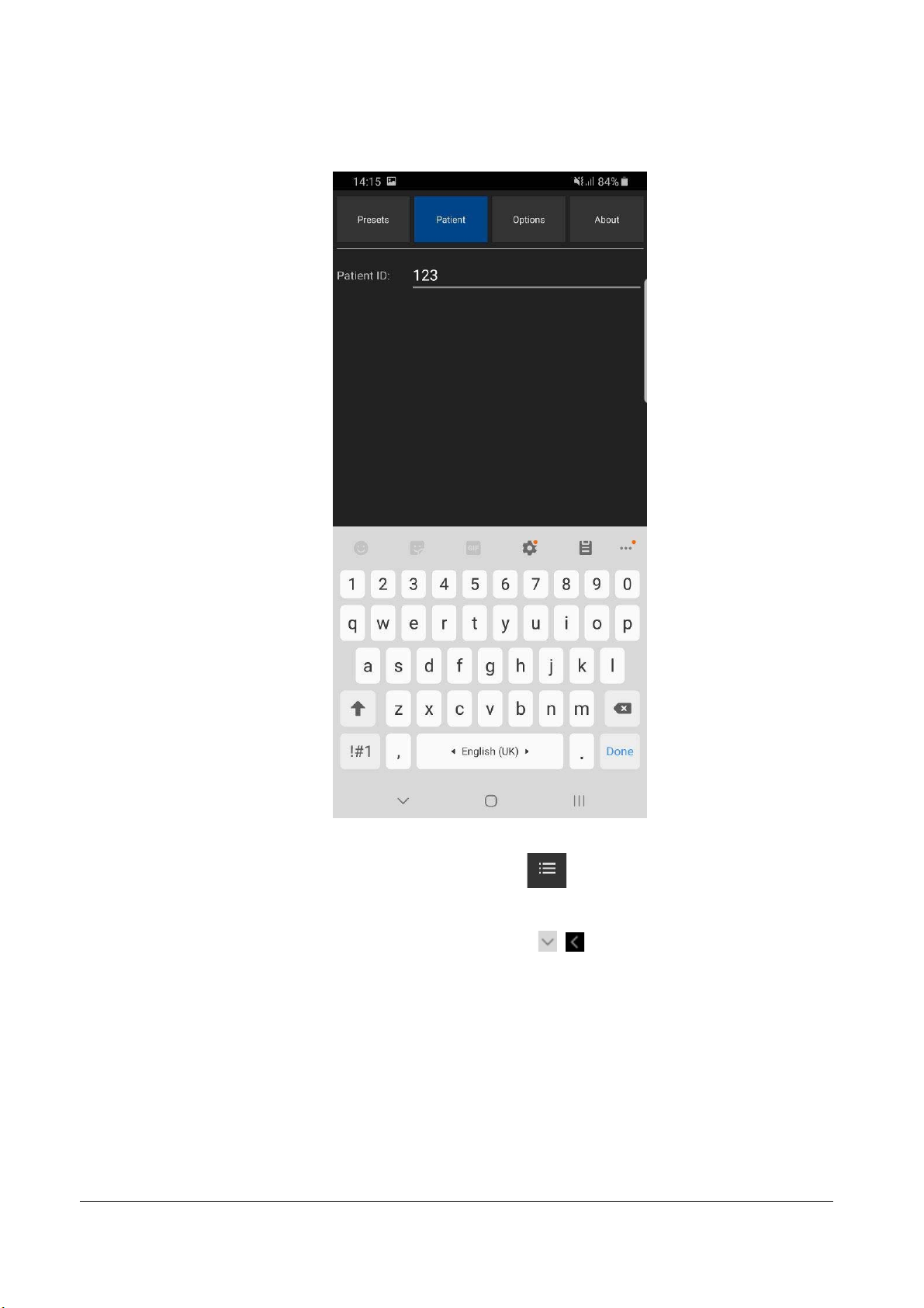
6. Patient Information
To enter patient identifier, please perform the following actions:
1.
Open the Settings window by clicking on the "Settings" button , then click “Patient” button at the top.
2.
Click textbox after “Patient ID”.
3.
Enter patient identifier.
4.
Close keyboard and Settings window by clicking “Back” buttons
,
.
Patient identifier (if was entered) appears in file names of saved image and video files.

TELEMED
Echo Wave A Software User Manual Ver. 1.2.1 2020.07.02 Page 11 of 25
7. Adjusting Ultrasound Image Quality
To adjust desired scanning parameter, click corresponding button at the bottom of software window
and do sweeps on ultrasound image (depending on control type). Control types were described in section
“Types of Controls” of this document. All scanning parameters will be described in next sections. If any
parameter is controlled using other method, then this information will be presented in the section that
describes this parameter. Buttons of scanning parameters are organized to multiple rows, and to show other
parameters (that are not initially visible) must be done vertical sweeps on buttons placement area.
7.1.Adjusting B Mode Controls
7.1.1.
Focus
Description
Focus optimizes the ultrasound image by increasing the resolution of specific areas. Always try to
adjust focuses so that focusing markers are at the center of the anatomical structure which is of most interest.
Values
The available list of focusing depth values depends on the probe used. Focusing depth
measurement units used - millimeters (mm).
Adjustment
To change focusing depth, wait while scanning controls will become inactive and then do vertical
sweeps with finger along vertical B mode scale line.
Relations to other controls
After adjusting Depth you may need to adjust the Focus controls.
7.1.2.
Depth
Description
Depth adjusts the field of view. Increase the depth to look at larger or deeper structures. Decrease
depth in order to look at structures near the skin surface. Additionally, you may wish to decrease the depth if
there is a large part of unnecessary ultrasound image below the displayed anatomical structures of interest.
You may also need to change the depth in order to see anatomical structures of interest in the center of the
screen.

TELEMED
Echo Wave A Software User Manual Ver. 1.2.1 2020.07.02 Page 12 of 25
Values
The list of available depth values depends on the type of probe used. Measurement units used -
millimeters (mm). The painted depth scale on the ultrasound image displays tick marks at 10 mm intervals.
Adjustment
Click “Depth” button and do sweeps on ultrasound image.
Relations to other controls
After adjusting the Depth you may need to adjust the Gain, TGC (Time Gain Compensation) and the
Focus controls.
Smaller scanning depths usually allow you to achieve higher frame rates (FPS - Frames Per Scond).
7.1.3.
Dynamic Range
Description
Dynamic range is a measure of the ultrasonic device's ability to display both very weak and very
strong signals at the same time while ensuring their levels can still be visually distinguished. The greater the
dynamic range the better the above-mentioned ability. As a rule, every observation should be started using
the maximum possible dynamic range since it provides you with the most complete diagnostic information.
Narrowing or reducing the dynamic range leads to the echo image displaying more contrast. Dynamic Range
is useful for optimizing tissue texture for different anatomical structures.
Values
The values available depend on the type of probe used. Measurement units used - decibels (dB).
Adjustment
Click “Dynamic Range” button and do sweeps on ultrasound image.
Hints
Adjust the Dynamic Range so that the highest amplitude edges appear as white while the lowest
levels (such as for blood) are only just visible.
7.1.4.
Power
Description
Power adjustment increases or decreases the acoustic power of the transmitted ultrasound signal.
Larger power values allow you to increase the penetration depth and can help to achieve better image
quality when observing tissues at greater depths.
Values
Available power values usually are in the interval [-20;0] dB. Measurement units used - decibels (dB).
Adjustment
Click “Power” button and do sweeps on ultrasound image.

TELEMED
Echo Wave A Software User Manual Ver. 1.2.1 2020.07.02 Page 13 of 25
Relations to other controls
After adjusting the Power level you may need to adjust the Gain. If you decrease the power level you
may need to increase the gain. If you increase the power level you may need to decrease the gain.
Hints
Always optimize gain before increasing power levels.
Caution
Always use the lowest possible power value in order to reduce any possible negative effects on the
patient. This is especially important when observing pregnant women and children.
7.1.5.
Gain
Description
Gain adjustment increases or decreases the amplification of the returning ultrasound echo signal.
Use this control to increase or decrease the amount of echo information displayed in the ultrasound image.
Gain adjustment allows you to balance echo contrast so that cystic structures appear echo-free and
reflecting tissues are filled in. Gain adjustment may brighten or darken the ultrasound image if sufficient echo
information is generated.
Values
Gain values available are usually found in the interval 10-100%. Measurement units used -
percentages (%).
Adjustment
Click “Gain” button and do sweeps on ultrasound image.
Relations to other controls
After adjusting the Gain you may need to adjust the Power level. If you increase the gain then you
may need to decrease the power level. If you increase the power level you may need to decrease the gain.
Please note that adjustments of the Gain control do not change the shape of the TGC (Time Gain
Compensation) curve. Gain control adjusts overall gain while TGC controls adjust the gain at appropriate
depths.
Hints
Always optimize gain before increasing the power level.
7.1.6.
Change Scan Direction
Description
The Change Scan Direction (Reverse) control allows you to change the ultrasound scanning
direction without rotating the probe. Use this feature when you wish to scan an anatomically correct
ultrasound image without rotating the probe.
Adjustment
Click “Change Scan Dir.” button.

TELEMED
Echo Wave A Software User Manual Ver. 1.2.1 2020.07.02 Page 14 of 25
Caution
When scanning, please observe the scan direction marker that is painted on the ultrasound image
in order to avoid any possible confusion.
7.1.7.
Frequency
Description
Frequency is a characteristic that defines the resolution of ultrasonic signal. Higher frequencies
increase resolution of the incoming ultrasonic signal but reduce the visibility of examined tissues at greater
depths. In order to examine tissues found at small depths use larger frequencies and when examining
tissues at greater depths it is better to use small frequencies.
Values
The frequency values available depend on the type of probe used. Measurement units used -
megahertz (MHz).
Adjustment
Click “Frequency” button and do sweeps on ultrasound image.
7.1.8.
FrameAveraging
Description
Frame averaging is an image processing technique that allows you to obtain smoother, softer
images and reduces ultrasound image noise by averaging several sequential ultrasound image frames
together. Use higher frame averaging values to obtain smoother images.
Values
The values available may differ depending on the type of probe but the following values are usually
available: Off, 2, 3, ..., 8. These values mean the number of averaged frames. “Off” means that frame
averaging is not used.
Adjustment
Click “Frame Averaging” button and do sweeps on ultrasound image.
Caution
Please note that higher frame averaging values not only make ultrasound images smoother but may
also hide small image details. Frame averaging may slightly decrease the frame rate.
7.1.9.
Rejection
Description
Ultrasonic signal rejection is a processing that changes a range of the values of the ultrasonic signal
received. Generally speaking, this processing is used to reduce visibility of noises on ultrasonic images.

TELEMED
Echo Wave A Software User Manual Ver. 1.2.1 2020.07.02 Page 15 of 25
Values
The range of values usually available is 0-32. The value means at what level the gray scale values
are rejected. A value of 0 means that no rejection is performed. Higher values mean that more data is
rejected.
Adjustment
Click “Rejection” button and do sweeps on ultrasound image.
7.1.10.
ImageEnhancement
Description
Ultrasound images can be enhanced by using smoothing filters that remove noise or by using
sharpening filters that enhance the tissue boundary visibility (e.g., for vessels).
Values
The software displays indexes of the image enhancement methods available. “Off” means that
image enhancement is not used.
Adjustment
Click “Image Enhanc.” button and do sweeps on ultrasound image.
Relations to other controls
Enabled image enhancement may reduce frame rate. If your want higher frame rates you may need
to turn off the image enhancement.
7.1.11.
SpeckleReduction
Description
Speckle reduction is an image enhancement technique that reduces speckle noise and allows to
view smoother ultrasound images.
Values
The software displays values that correspond to speckle filtration level.
Adjustment
Click “Speckle Reduction” button and do sweeps on ultrasound image.
Relations to other controls
Enabled speckle reduction may greatly reduce frame rate and slow down software operation. If your
want higher frame rates, you may need to turn off the speckle reduction.

TELEMED
Echo Wave A Software User Manual Ver. 1.2.1 2020.07.02 Page 16 of 25
7.1.12.
Lines Density
Description
Lines density adjusts the number of ultrasonic beams that are used for scanning ultrasound image.
Use a higher density when you are viewing small objects. A lower density allows you to increase the frame
rate and can be used when viewing fast moving objects (for example the heart).
Adjustment
Click “Lines Density” button and do sweeps on ultrasound image.
7.1.13.
Map
Description
The software allows to select gray/color map that defines how 256 input grayscale values from the
interval [0;255] are transformed to output values. When is used linear map, output values are the same as
input values (that is, no mapping is used).
Values
The software displays indexes of available maps. “1” means linear map.
Adjustment
Click “Color Map” button and do sweeps on ultrasound image. Gamma
7.1.14.
Gamma, Brightness, Contrast
Description
The software allows you to adjust the ultrasound image palette using gamma, brightness and
contrast controls. Gamma adjustment changes the gray scale values of the ultrasound image in a non-linear
manner by raising the normalized values to the power of the chosen gamma value. To make the entire
ultrasound image appear lighter you can increase the brightness value. By increasing the contrast value you
can increase the difference between the image gray scale values and make the ultrasound image appear
sharper.
Adjustment
Click “Palette”, “Gamma”, “Brightness” or “Contrast” button and do sweeps on ultrasound image.
Gamma correction is not used if the level 1 is selected, brightness correction is not used if the level 0 is
selected and contrast correction is not used if the level 0 is selected.
Hints
Before adjusting the ultrasound image Gamma, Brightness or Contrast, it is recommended that you
perform the correct ultrasound image adjustment using the Gain, TGC, Power, and Dynamic Range controls.

TELEMED
Echo Wave A Software User Manual Ver. 1.2.1 2020.07.02 Page 17 of 25
7.1.15.
Negative
Description
In order to invert the palette of the ultrasound image (change the dark gray scale values to light and
vice versa) you can use the Negative control.
Adjustment
Click “Negative” button.
7.1.16.
Zoom
To perform zoom in or zoom out of the B mode ultrasound image, click “Zoom” button and do
sweeps on ultrasound image. Zooming also can be performed by touching B mode image with two fingers
simultaneously and expanding/contracting them. When the image is zoomed and scanning controls are not
active, the image can be shifted by doing sweeps to any direction somewhere in the center of B mode image.
Default zoom value (when no zoom is used) is 100%. In order to reset zoom to default, click on B mode
ultrasound image.

TELEMED
Echo Wave A Software User Manual Ver. 1.2.1 2020.07.02 Page 18 of 25
7.1.17.
TGC (Time Gain Compensation)
The Time Gain Compensation (TGC) controls adjust how returning signals are amplified in order to
correct the attenuation that varies depending on the scanning depth and the tissue being observed. Using
the TGC controls you can equalize amplification of the returning echo signal so that the density of echoes at
different depths is similar. TGC allows you to control the gain level in several depth zones independently.
TGC control points are spaced proportionally to the current scanning depth. Small circular markers on this
curve correspond to the TGC control points.
Values
TGC values available are in the interval 0-100% (in software they are not shown). Measurement
units used - percentages (%).
Adjustment
When scanning controls are not active, press and hold for several seconds on ultrasound image (at
any depth) at the right of depth scale line to show TGC curve. Then, while TGC curve is visible, do horizontal
sweeps on ultrasound image at desired to change TGC control points (depth) that are painted as small
circular markers. Software will automatically hide TGC curve when it is not changed for some time.
Relations to other controls
To adjust the overall gain use the B mode Gain control. After adjusting the Depth you may need to
adjust the TGC.
TELEMED
Echo Wave A Software User Manual Ver. 1.2.1 2020.07.02 Page 19 of 25
8. Measurements and Calculations
This section describes the user interface for measurements and calculations. For equations and
references please see the "Echo Wave A Software Reference Manual".
8.1.B Mode Measurements
In order to perform B mode measurements, scan ultrasound image, freeze ultrasound by clicking
“Freeze/Run” button, click desired measurement button, do measurement by clicks/moves on the ultrasound
as will be described in next sections.
8.1.1.
Distance
To measure distance, perform the following actions:
1.
Click “Distance” button . Button color is changed .
2.
Press and move with finger on the ultrasound image in order to set position of first point. When done,
release finger. That is, do operation that in the future will be called press-move-release.
3.
Press-move-release on the ultrasound image to set second point and finish measurement.
4.
Optionally, perform another measurement of the same type by repeating steps 2-3.
Measurement object and result:
At first endpoint is displayed measurement number (“1:”) and measurement result (“48.6 mm”).
Please note that when measurement operation is in progress, painted measurement object has different
color than when measurement is finished.
8.1.2.
Area, Circumference and Volume using Ellipse
To measure area, circumference and volume using ellipse, perform the following actions:
1.
Click “Area (Ellipse)” button . Button color is changed .
2.
Press-move-release on the ultrasound image to set first point (long axis).
3.
Press-move-release to set second point (long axis).
4.
Press-move-release to set third point (short axis) and finish measurement.
5.
Optionally, perform another measurement of the same type by repeating steps 2-4.

TELEMED
Echo Wave A Software User Manual Ver. 1.2.1 2020.07.02 Page 20 of 25
Measurement object (ellipse) and result:
At first endpoint is displayed measurement number (“1:”) and measurement result: “17.26 cm2” area,
“P=154.5 mm” circumference and “V=43.236 cm3” volume.
Please note that for ellipse long axis (first axis) are marked two endpoint markers, while for short
axis (second axis) is marked only one endpoint.
8.2.Deleting Performed Measurements
To delete measurement, click “Delete” (“Undo”) button . Measurements are deleted one by one
starting from last done measurement.
This manual suits for next models
1
Table of contents
Popular Medical Equipment manuals by other brands


Getinge
Getinge Arjohuntleigh Nimbus 3 Professional Instructions for use

Mettler Electronics
Mettler Electronics Sonicator 730 Maintenance manual

Pressalit Care
Pressalit Care R1100 Mounting instruction

Denas MS
Denas MS DENAS-T operating manual

bort medical
bort medical ActiveColor quick guide

AccuVein
AccuVein AV400 user manual


