Telenot hiplex 8400H BT 800 User manual
INTRUDER ALARM
CONTROL PANEL
hiplex®8400H
BT800/820
Version (06) USER MANUAL english

2
1 User notes
Before using the product, read the user manual carefully
and keep it for future reference.
Do not open the product. All installation and main-
tenance work may only be carried out by an expert
installer.
The user manual describes an intruder alarm control pa-
nel that is installed in accordance with VdS guidelines.
Exceptions are indicated in the text.
Illustrations are intended to help the reader to under-
stand the content in general, and can deviate from the
actual design.
2 Table of content
1 User notes . . . . . . . . . . . . . . . . . . . . . . . . . . . 2
2 Table of content . . . . . . . . . . . . . . . . . . . . . . .2
3 Terms, abbreviations, and symbols . . . . . . . . . . . . 4
3.1 Terms . . . . . . . . . . . . . . . . . . . . . . . . . . . . . . . 4
3.2 Abbreviations. . . . . . . . . . . . . . . . . . . . . . . . . . 8
3.3 Symbols . . . . . . . . . . . . . . . . . . . . . . . . . . . . . 8
4 Basics of the intruder alarm system . . . . . . . . . . .9
4.1 Structure . . . . . . . . . . . . . . . . . . . . . . . . . . . . 9
4.2 Partitions . . . . . . . . . . . . . . . . . . . . . . . . . . . 10
4.3 Setting states. . . . . . . . . . . . . . . . . . . . . . . . . 10
4.3.1 Externally set . . . . . . . . . . . . . . . . . . . . . . . . 10
4.3.2 Internally set . . . . . . . . . . . . . . . . . . . . . . . . 11
4.3.3 Unset . . . . . . . . . . . . . . . . . . . . . . . . . . . . . 11
4.3.4 Alarm status and resetting . . . . . . . . . . . . . . . 12
4.4 Detector . . . . . . . . . . . . . . . . . . . . . . . . . . . . 12
5 Keypad . . . . . . . . . . . . . . . . . . . . . . . . . . . . 14
5.1 Structure of touch keypad BT800/801. . . . . . . . . 14
5.1.1 "Keypad" screen page. . . . . . . . . . . . . . . . . . . 14
5.1.2 "Indication panel1/2" screen page . . . . . . . . . . 18
5.1.3 "Overview" screen page . . . . . . . . . . . . . . . . . 19
5.1.4 “Switching actions” screen page. . . . . . . . . . . . 19
5.1.5 Settings menu . . . . . . . . . . . . . . . . . . . . . . . 20
5.2 Structure of BT820 . . . . . . . . . . . . . . . . . . . . . 21
5.3 Access levels . . . . . . . . . . . . . . . . . . . . . . . . . 21
5.4 Menu structure . . . . . . . . . . . . . . . . . . . . . . . 23
5.4.1 Alarm memory . . . . . . . . . . . . . . . . . . . . . . . 24
5.4.2 Indication test . . . . . . . . . . . . . . . . . . . . . . . 24
5.4.3 Walk test. . . . . . . . . . . . . . . . . . . . . . . . . . . 25

3
Table of content
5.4.4 Change the code. . . . . . . . . . . . . . . . . . . . . . 25
5.4.5 Disable input groups . . . . . . . . . . . . . . . . . . . 26
5.4.6 Overriding the setting prevention. . . . . . . . . . . 26
5.4.7 Reset tamper . . . . . . . . . . . . . . . . . . . . . . . . 27
5.4.8 Event memory . . . . . . . . . . . . . . . . . . . . . . . 28
5.4.9 Alarm counter . . . . . . . . . . . . . . . . . . . . . . . 29
5.4.10 Disable personal enabling codes? . . . . . . . . . . . 30
5.4.11 Identify transponder . . . . . . . . . . . . . . . . . . . 31
5.4.12 Closing element battery change. . . . . . . . . . . . 31
5.4.13 Service enabling . . . . . . . . . . . . . . . . . . . . . . 32
5.4.14 App enabling . . . . . . . . . . . . . . . . . . . . . . . . 32
5.5 Operation with keypad. . . . . . . . . . . . . . . . . . . 33
5.5.1 External setting . . . . . . . . . . . . . . . . . . . . . . 33
5.5.2 Internal setting. . . . . . . . . . . . . . . . . . . . . . . 34
5.5.3 Unsetting . . . . . . . . . . . . . . . . . . . . . . . . . . 34
5.5.4 Setting externally with exit time . . . . . . . . . . . 35
5.5.5 Unsetting with entry time . . . . . . . . . . . . . . . 35
5.5.6 Resetting alarms, faults, and battery warnings . . 36
6 Switching device . . . . . . . . . . . . . . . . . . . . . . 37
6.1 Structure of the reader cryplockR/K-MD . . . . . . . 37
6.2 Structure of the reader comlockR-ED . . . . . . . . . 37
6.3 Operation with reader . . . . . . . . . . . . . . . . . . . 38
6.3.1 External setting . . . . . . . . . . . . . . . . . . . . . . 38
6.3.2 Unsetting . . . . . . . . . . . . . . . . . . . . . . . . . . 40
6.4 Operation with switching lock . . . . . . . . . . . . . . 42
6.4.1 Shunt lock . . . . . . . . . . . . . . . . . . . . . . . . . . 42
6.4.2 Pulse switching lock . . . . . . . . . . . . . . . . . . . 43
7 System does not set. What can I do? . . . . . . . . . . 44
8 Maintenance and care. . . . . . . . . . . . . . . . . . . 46
9 Behavior in case of analarm . . . . . . . . . . . . . . . 47
9.1 Alarm (when externally set) . . . . . . . . . . . . . . . 47
9.2 Alarm (when internally set). . . . . . . . . . . . . . . . 47

4
Terms, abbreviations, and symbols
3 Terms, abbreviations, and symbols
3.1 Terms
Tear-off detector
The housing of an intruder alarm system can be equipped
with a tear-off detector that detects and reports the removal
(tear-off) of the housing from the wall (tamper protection).
Alarm
Warning about danger to life and property.
Alarm counter
A counter built into the intruder alarm control panel that cannot
be reset, which counts every intrusion, hold-up, or tamper alarm
(for documentation purposes).
Indication panel
Part of some keypads. The indication panel shows the status of
16or 32input groups by means of LEDs. It also offers the option
of disabling/enabling input groups for setting (depending on
the parameterization).
Response authority
A person appointed by the responsible operator, who receives
messages and initiates the necessary measures (assistance),
e.g. surveillance and security service or police.
Responsible operator
The person responsible for operating the intruder alarm system
and the group of people authorized by him/her to operate it.
Motion detector
A detector that detects and reports movements within its sur-
veillance area.
Shunt lock
A switching device in the form of a lock that is integrated in the
door and can be used to set and unset the system. The shunt
lock also prevents setting for as long as a setting prevention
criterion is present (see Coerciveness).
Exit time/entry time
An exit and entry time is used to set or unset the intruder alarm
system using a keypad that is located within the partition. In
this case, an exit time is required to allow persons to exit the
property after setting the system on the keypad. At the same
time, an entry time is required to allow entry into the partition
for unsetting the system without activating an alarm. This func-
tion is not in compliance with VdS directives.

5
Terms, abbreviations, and symbols
Externally set
The responsible operator sets the system when he/she is not
present in the property. The activation of an alarm results in an
external alarm.
External alarm
Alerting using an externally installed warning device (siren and
strobe beacon) and/or the sending of a message to the response
authorities.
False alarm
An alarm for which no danger actually exists. The following cau-
ses can lead to false alarms:
Persons or pets that are accidentally locked in
Subsequent structural changes in the surveillance area of
detectors, e.g. curtains waving and air drafts
Insufficient maintenance of the system
Remote alerting
Alerting whereby a message is sent to the response authorities.
Walk test function
The walk test is used to check and configure the surveillance
area of a motion detector. The LED on the detector is illumi-
nated as long as a person is moving in the surveillance area
and is detected by the detector.
Glass-break detectors
A detector that detects and reports the breakage of a glass
pane. You can recognize the triggered detector by its LED.
First alarm indication
The first input (dedicated signal or input group) triggered in
the event of an alarm is specially indicated on the keypad, e.g.
by blinking of the indicator. The first alarm indication indicates
where the intruder entered the property.
Intruder alarm system
The entire system with all detectors and the intruder alarm
control panel.
Installer
A specialist firm that installs intruder alarm systems and
carries out service and maintenance work. The employees
of the installer firms are trained by the manufacturer of the
intruder alarm system. The installer firms must be approved
by VdSSchadenverhütungGmbH in order to install systems in
compliance with VdS directives.
Tamper contact
The intruder alarm system components' lids or parts of the
housings that can be opened are equipped with tamper con-
tacts that detect and report when the components are opened
(tamper protection).

6
Terms, abbreviations, and symbols
Transponder
An electronic key for operating an electronic switching device.
The transponder for actuation of the switching procedure is
held in front of the reader belonging to the switching device.
The transponder is identified by a near-field wireless connection.
Pulse switching lock
A switching device in the form of a lock that is installed beside
the door and can be used to set and unset the system.
Internally set
The responsible operator sets the system when he/she is
present in the property. The activation of an alarm results in an
internal alarm.
Internal alarm
A signal is output by means of audible warning devices that
are only installed within the property under surveillance. An
internal alarm is only executed if the system is in the unset
(e.g. fire detector) or internally set state.
LED
Light-emitting diodes are reliable, long-lasting and energy-sa-
ving electronic components. LEDs of different colors are used.
Magnetic contact
A contact that detects and reports the opening of, for example,
doors and windows.
Input group
An input group combines multiple dedicated signals in order to
display and (if necessary) disable them together on the keypad,
e.g. motion detectors if the system is internally set.
Dedicated signal
An alarm source (detectors or inputs) that is individually de-
tected, processed, and indicated by the intruder alarm control
panel.
Input
Physical connection of multiple detectors to a common input on
the intruder alarm control panel. The processing performed by
the intruder alarm control panel as well as the indication on the
keypad is equivalent to that of an individual dedicated signal.
Alternative power source
If there is a power supply failure of the 230 V mains supply, the
function of the entire system must be guaranteed for at least
12hours (in compliance with VdS classA). To meet this require-
ment, the intruder alarm control panel is fitted with a built-in
rechargeable battery. The rechargeable battery is monitored by
the intruder alarm control panel. In the event of a power supply
fault, the intruder alarm system cannot be set (coerciveness).
Switching device
Switching devices are used to set and unset the system. For ex-
ample, it can be a shunt lock, a bolt switching lock, a switching
lock or a reader.

7
Terms, abbreviations, and symbols
Lock state monitoring
The locks on all access doors to partitions are fitted with bolt
contacts that monitor the lock state of the doors. It ensures
the coerciveness when the system is set. The partitions can
only be set if all access doors are locked. The status of lock
state monitoring is displayed on the keypad.
Coerciveness
On the one hand, coerciveness prevents the intruder alarm
control panel from being set as long as a setting prevention
criterion is present, e.g. if a detector is activated, a door/win-
dow opened, or if a fault state is pending. On the other hand,
coerciveness prevents the unintentional entry into the partition
as long as the system is still set (see Blocking element).
Silent alarm
Alerting which involves sending a message to the response
authorities without activating an internal/external alarm. This
alarm is used for hold-ups.
Transmission device
A telecommunications device built into the intruder alarm
control panel, which automatically transmits alarm, state, and
fault messages via a telecommunication network to an alarm
receiving center (response authority).
Unset
The system is not set. Nevertheless, some functions are still
active, e.g. tamper monitoring, fault monitoring, evaluation of
the technical detector, etc.
VdS (VdSSchadenverhütungGmbH)
An institution supported by the German Insurance
Industry whose functions include drafting standardized
guidelines and testing criteria for intruder alarm systems
and carrying out approval testing of intruder alarm system
concepts and specialist firms.
VdS class
Depending on the threat potential and the number of valuable
items in the building, the insurance company can prescribe an
intruder alarm system with a VdS class (protection class). There
are three VdS classes: A, B and C (VdS classC calls for the stric-
test protective measures).
Blocking element
If an intruder alarm system is set, the blocking element blocks
the door to the partition. Unintentional entry into the partition
and the resulting activation of a false alarm are not possible
(coerciveness).
8
Terms, abbreviations, and symbols
3.2 Abbreviations
General
Keypad = Keypad
IACP = Intruder alarm control panel
TD = Transmission device
Partition status
Ea = External alarm
Ee = External exit time
Es = Externally set
Ev = External entry time
Ia = Internal alarm
Ie = Internal exit time
Is = Internally set
Iv = Internal entry time
Ua = Unset alarm
Us = Unset
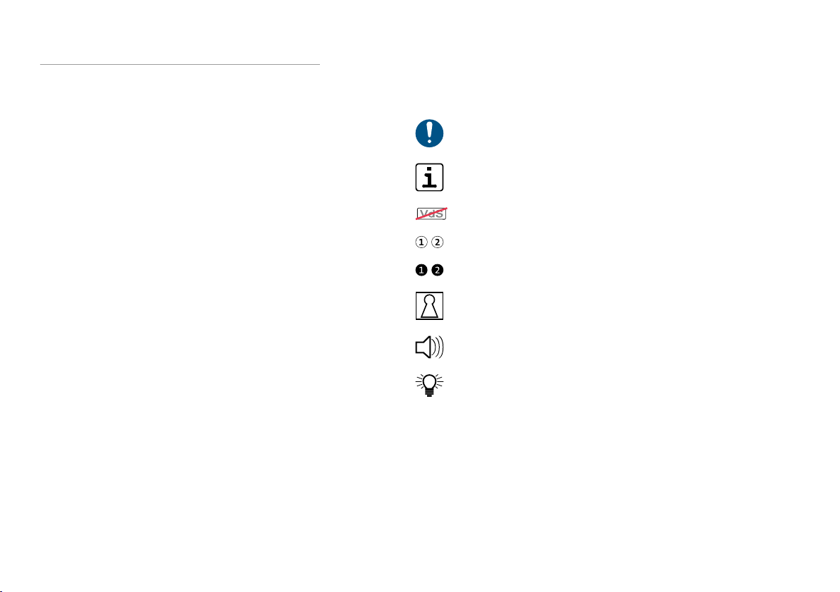
3.3 Symbols
Important notice, order
Tips, recommendations, useful information
Usage not in compliance with VdS directives
Legend
Sequence of action
Switching device
Buzzer
LED
9
Basics of the intruder alarm system
4 Basics of the intruder alarm system
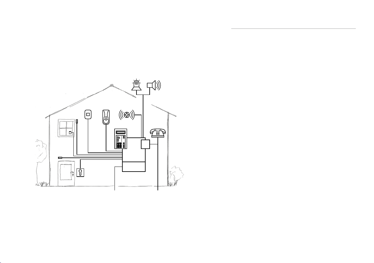
4.1 Structure
External warning devices
Strobe BeaconSiren
Window
contact
Hold-up
detector
Motion
detector
Internal
warning
devices
Glass-break
detector
Keypad
TD
Door contact
Switching
device
IACP
complex 400H
Power supply unit
with rechargeable
battery
230 V ~ mains connectionTelephone connection
Structure of an intruder alarm system
The intruder alarm control panel (IACP) controls and monitors
all functions. It supplies the entire system with electrical power.
For this, the IACP features an integrated power supply unit
which converts the 230V mains supply to 12V DC.
The TD (transmission device) transmits alarm, state, and fault
messages to a response authority, e.g. surveillance and security
service. The TD uses the telecommunications network for trans-
mission.
Messages to the responsible operator on site are shown on
the keypad display. With the help of the numeric pad on the
keypad, the responsible operator can operate the system, e.g.
look up stored information or disable input groups. Any posi-
tion within the partition, e.g. the IACP housing, is suitable as a
mounting location.
The detectors monitor the property, e.g. magnetic contacs on
doors and windows, glass-break detectors, motion detectors,
etc. They are combined physically into inputs and connected to
the IACP inputs. Consequently, the control panel is continuous-
ly informed about the status of all detectors, e.g. whether a
window is open.
If a detector detects that a window or a door is open, an alarm
should only be activated if the responsible operator has set the
system using the switching device.
The alerting on site is performed by the indoor warning devices
when the system is internally set and by the outdoor warning
devices when it is externally set.
10
Basics of the intruder alarm system
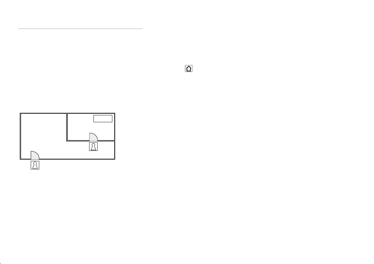
4.2 Partitions
An intruder alarm system can include several partitions. The-
se partitions can be set or unset either in a mutually depen-
dent manner or completely independently of one another. In
this case, each partition has its own switching device and (if
necessary) a separate keypad.
Example
Strong room1 can only be set if strong room2 was set first.
IACP
Partition
e.g. Strong room 1
Dependent partition
e.g. Strong room 2
SD1
SD2
Dependent partition
4.3 Setting states
4.3.1 Externally set
The system is set with no persons inside the partition(s).
The following criteria must be fulfilled for the external setting:
No person is inside the partition
All detectors are in the ready-to-set state
No pending faults
Switching device is used for external setting and subsequent un-
setting. There are different types of switching devices, e.g. shunt
locks, bolt switching locks or readers.
In case of an alarm activation, local alerting is performed by the
outdoor warning devices. In compliance with VdS, additional
remote alerting via the transmission device is necessary.

11
Basics of the intruder alarm system
4.3.2 Internally set
The system is set with persons present in the partition(s).
The keypad or an internal switching device is used for
internal setting and subsequent unsetting. It is possible to
disable specific dedicated signals (e.g. motion detectors) to
enable entry into rooms in the property.
In case of alarm activation, local alerting is performed by the
indoor warning devices. As an option, an external alarm and/
or remote alerting can be additionally activated after a defi-
ned time and under the requirement that the alarm was not
previously reset at the keypad (not in compliance with VdS
directives).
4.3.3 Unset
The system is not set.
While the system is unset, some functions of the intruder
alarm control panel will still be active. Important functions will
never be switched off.
Indication
The current states are indicated on the keypad.
Tamper
The IACP checks the cable connections to the keypads, to
the switching devices and to the external warning devices.
Likewise, the housings of all components are monitored for
opening. Depending on the parameterization, a tampering
attempt results in an internal or external alarm.
Fault
The IACP monitors the voltage supply, the rechargeable
battery, the transmission device, and the function of the
transmission paths used. Faults that occur are indicated
visually and audibly on the keypad. Transmission of faults is
possible independent of the current setting state.
Coerciveness
If a tamper alarm, an intruder alarm, or a fault is pending,
the system cannot be set (coerciveness). Lock state moni-
toring also affects the coerciveness, i.e., if a detector is not
in the ready-to-set state (e.g. a window is open), it is not
possible to set the intruder alarm system.

12
Basics of the intruder alarm system
4.3.4 Alarm status and resetting
After an internal or external alarm is activated, the IACP switches
to the alarm state. In the alarm state, the indoor and/or outdoor
warning devices in the system are activated (max. up to un-
setting). Depending on the parameterization, the transmission
device transmits an alarm message to the response authorities.
During unsetting, the switching device signals the pending
alarm. In the unset state, only the alarm LED and the buzzer on
the keypad indicate the alarm state. Only after the IACP is reset
does this signaling also end, which means that the system can
be set again (see Keypad/ Operation with keypad/ Resetting
alarm, faults and battery warning).
On VdS class B and C systems, the responsible operator is unable
to reset a tamper alarm. The reset can only be performed by
the installer of the system, who also determines the reason for
activation, checks that the system is functioning correctly and
seals the housing.
4.4 Detector
To ensure that the IACP can detect and report different hazar-
dous situations, a variety of detector types must be installed
in the system. Each detector type is intended for a particular
hazardous situation.
The table below shows how the system reacts depending on the
setting state. Depending on the parameterization, the actual
reaction of the system may differ from the example shown here.

13
Basics of the intruder alarm system
Detector Reaction of system
Unset Internally
set
Exter-
nally set
Magnetic contact on
doors and windows
Only displayed
on keypad
Internal
alarm
External
alarm4
Motion detector Only displayed
on keypad
Internal
alarm
External
alarm4
Glass-break detec-
tors
Internal alarm Internal
alarm
External
alarm4
Tamper contact1Internal alarm Internal
alarm
External
alarm4
Smoke alarm device2Internal alarm Internal
alarm
External
alarm4
Technical detector
(e.g. water or gas
detector)
Internal alarm Internal
alarm
External
alarm4
Escape door moni-
toring3
Internal alarm Internal
alarm
External
alarm4
Motion detectors in
outdoor areas
Only displayed
on keypad
Activation of exterior
lightning
Bolt switch contact
of doors and win-
dows
No alarm, prevents setting (coercive-
ness)
Hold-up alarm
device
Silent alarm
Table: Detector and reaction of the system
1The housings on all components are fitted with tamper
contacts or similar protective mechanisms, which activate
a tamper alarm in response to a mechanical attack on the
components.
2When activated, the smoke alarm devices trigger a fire
alarm (additional function). However, the installation of
these detectors does not make the system into a fire detec-
tion and fire alarm system as defined by EN52.
3In the case of day monitoring of buildings that are open to
the public, external doors that must not be locked for safety
reasons (e.g. escape doors) are monitored. Opening these
doors leads to alerting.
4In compliance with VdS directives, additional remote aler-
ting using the transmission device is necessary.
14
Keypad
5 Keypad
A keypad is used for indicating operating states, alarms, and
faults, for setting/unsetting, alarm resetting and for entry of
additional control commands by the responsible operator.
TELENOT offers a variety of keypads for operating the IACP. For
information, refer to the TELENOT website at www.telenot.
com.
Operation of the IACP is explained below based on the examp-
le of the touch keypad BT800 and the LCD keypad BT820.
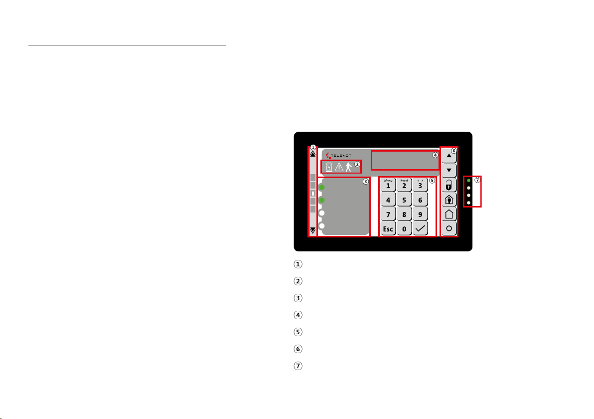
5.1 Structure of touch keypad BT800/801
5.1.1 "Keypad" screen page
The following control and indicating elements are available on
the touch keypad BT 800/801:
09:32
Mo 15.05.17
Ready for external setting
Unset
Internally set
Alarm
Switching of the screen pages
Icons
Freely parameterizable LEDs1–4
Display indication
Numeric block
Operating buttons
LED indication (operating states)
Structure of touch keypad BT800/801

15
Keypad
Switching of the screen pages
One screen page back
"Switching Functions" screen page
"Overview" screen page
"Keypad" screen page
"Indication Panel1" screen page
"Indication Panel2" screen page
One screen page forward
Switching of the screen pages
The page active in each case is visualized by the white square.
You can select the screen page also by selecting the gray rect-
angle directly (2-6) or by swiping vertically on the display.
Icons
Icons
Icons Color Function
Alarm Red Blinks for triggered and saved
alarms
Fault Yellow Blinks for pending and saved
faults
Walk test Green Blinks if walk test activated
(independent of partitions)
Table: Icon
16
Keypad
Freely parameterizable LEDs1–4
Ready for external setting
Unset
Internally set
Alarm
Freely parameterizable LEDs1–4
The freely parameterizable LEDs1–4 can indicate different
states (e.g. externally set, unset, internally set, alarm etc.). The
function, the text and the color of the LEDs are freely paramete-
rizable and are defined by the installer.
Display indication
12:19
Mo 20.01.14
Display indication
The display has a limited number of characters. Long
texts are divided in two indications, which are dis-
played alternatingly.
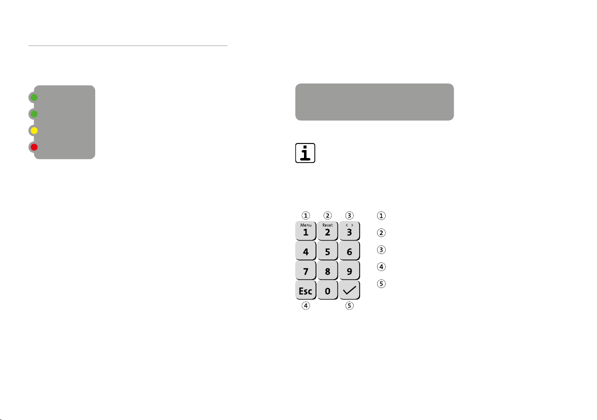
Numeric block
Menu/ digit1
Reset/ digit2
Selection/ digit3
Esc (cancel)
Enter (accept)
Numeric block

17
Keypad
LED indication (operating states)
LED indication (operating states)
LED indication
(operating states)
Color Function
Operation Green Illuminated during operation
and blinks during initialization
Alarm Red Blinks for triggered and saved
alarms
Fault Yellow Blinks for pending and saved
faults
Technical
alarm LED
Blue Blinks if technical functions are
activated
Table: LED indication
Operating buttons
Scroll (up)
Scroll (down)
Unsetting
Internal setting
External setting (only if enabled)
Freely parameterizable button
Operating buttons

18
Keypad
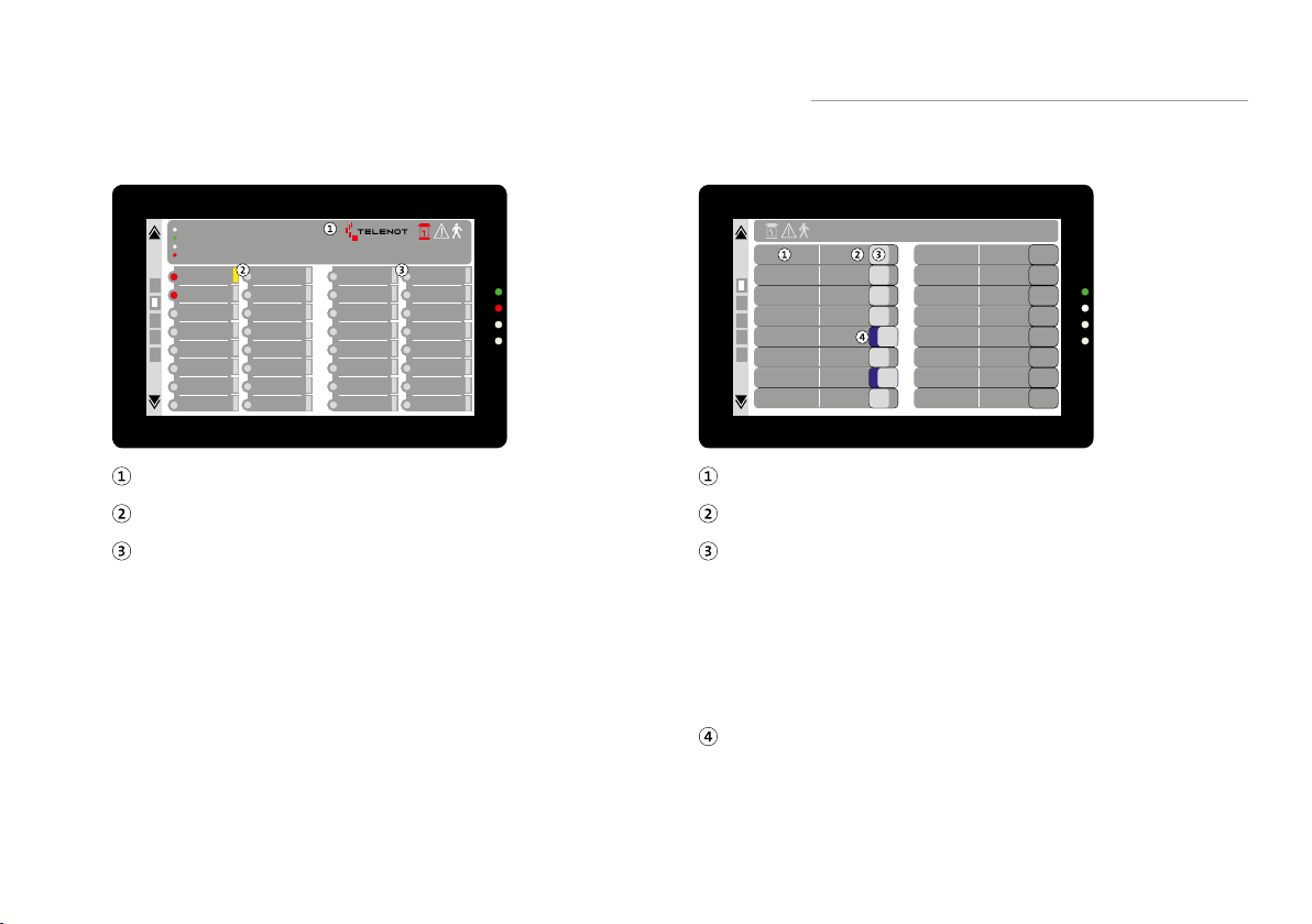
5.1.2 "Indication panel1/2" screen page
IG1 (Tamper)
Input group 2
Input group 3
Input group 4
Input group 5
Input group 6
Input group 7
Input group 8
Input group 9
Input group 10
Input group 11
Input group 12
Input group 13
Input group 14
Input group 15
Input group 16
IG-disabled LED
Input group text
IG-status LED
Button “Disable/enable input group”
"Indication panel1/2" screen page
The screen page “Indication panel1” of the touch keypad
displays the statuses of the first 16input groups; screen
page “Indication panel2” displays the statuses of ano-
ther 16input groups. Which input groups are displayed
depends on the parameterization.
IG-status LED: This LED (red) indicates whether at least one
dedicated signal in this input group is open or in the alarm
state.
Input group text: The input group text is displayed here as
defined in the IACP parameterization.
IG-disabled LED: This LED (yellow) indicateswhether an
input group is disabled. If the input group is enabled, the
LED is off.
Button “Disable/enable input group”: Use this button to
disable/enable the respective input group. Whether you can
disable an input group depends on the IACP parameterizati-
on and the access level.
19
Keypad
5.1.4 “Switching actions” screen page
Mo 15.05.17
09:32
Ds
Door 1
Ds
activate
Ds
Door 2
Ds
activate
Light
Corridor
switch on
Light
Basement
switch on
Garage door close
Shutters
Kitchen
close
Shutters
Living room
open
Pump switch on
Text/use of the switching action
Action text (ON/OFF) of the switching action
Button for activating the switching action
To activate or deactivate the switching switching action,
hold down the button.
For as long as you hold the button down, the entire row
(including the button) is colored orange. If you do not
hold down the button for long enough, a notice is dis-
played informing you of this (e.g. button > 1 s).
The blue display (area behind the button) indicates the
activated state of the switching action.
Screen page “Switching actions”
5.1.3 "Overview" screen page
Mo 15.05.17
Ready for external setting
Unset
Internally set
Alarm
IG1 (Tamper)
Input group 2
Input group 3
Input group 4
Input group 5
Input group 6
Input group 7
Input group 8
Input group 9
Input group 10
Input group 11
Input group 12
Input group 13
Input group 14
Input group 15
Input group 16
Input group 17
Input group 18
Input group 19
Input group 20
Input group 21
Input group 22
Input group 23
Input group 24
Input group 25
Input group 26
Input group 27
Input group 28
Input group 29
Input group 30
Input group 31
Input group 32
"Keypad" overview
"Indication Panel1" overview
"Indication Panel2" overview
"Overview" screen page
The "Overview" screen page of the touch keypad is a summary
view. It displays the screen pages "Keypad", "Indication Panel1"
and "Indication Panel2" in an overview. However, you cannot
perform any operations (e.g. using operating buttons, numeric
block, etc.).

20
Keypad
5.1.5 Settings menu
From the settings menu, the following parameters can be
adjusted:
Buzzer volume during button actuation
Brightness of the display
Brightness of the LED display
Color scheme of the display
Hold down (approx. 5s) the “Esc” button.
Mo 15.05.17
Ready for external setting
Unset
Internally set
Alarm
Start the settings menu
Enter the access enabling code (AL2) and confirm your input
with the “Enter” button. The access enabling code (AL2)
that you need to use depends on the parameterization. Ask
your installer.
1 2 3 4 5 6 7 8 9 0
# % & * / - + ( )
? ! " ' : ; ,
abc esc .
* * * * * 2
Enter code
Entering the acess-enableing code for the settings menu
Make the required changes.
To exit the settings menu, press the “double arrow” button.
This manual suits for next models
1
Table of contents
Other Telenot Control Panel manuals


