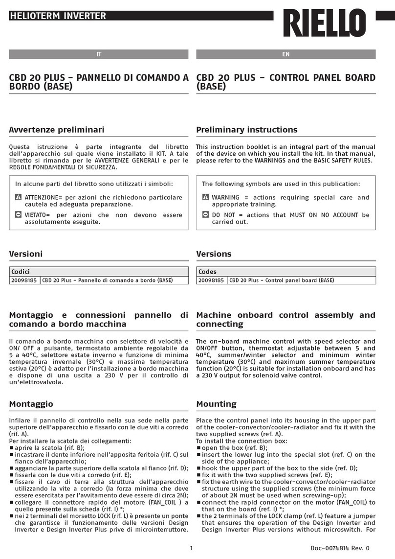
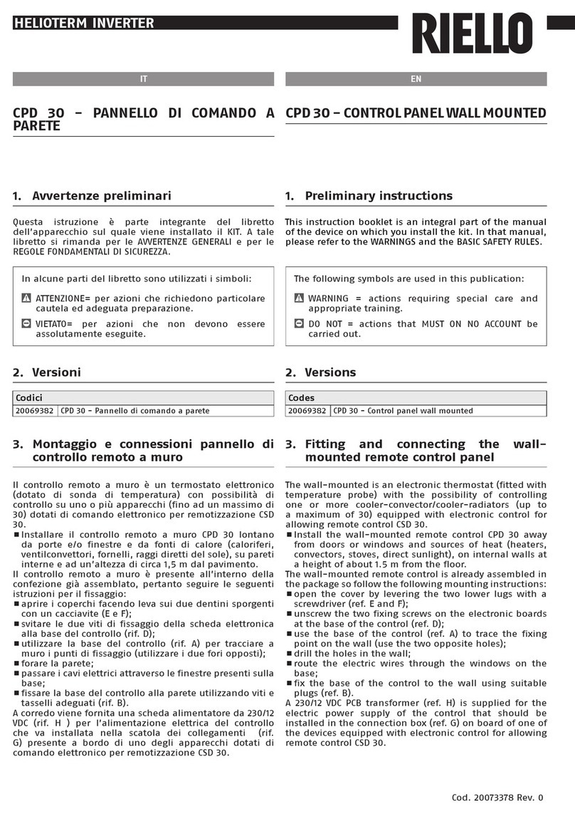
Riello Wired Touch panel User manual

cod.Doc-0090216rev.0
Wired Touch panel
06/2018
EN USER INSTRUCTIONS

2
www.riello.it
Support // Authorized Support Centre
9
The product must be used for its intended purpose, as stated by Rfor which it has
been expressly manufactured. Rshall bear no responsibility, whether of a contrac-
tual or non-contractual nature, for any damage caused to people, animals, or property
due to incorrect installation, adjustments, or maintenance, or improper use.
WARRANTY
Rproduct has a Conventional Warranty (valid for Italy, Republic of San Marino, Vatican
City), starting from the product's date of purchase.
Find the nearest Authorised Technical
Support by visiting the website
9
WARNING
Keep the product purchase documents for tax purposes to be presented to the Authorised
Technical Support upon request of a service call under warranty.
Dear customer,
Thank you for choosing a Rproduct, an innovative and high quality appliance that guar-
antees wellbeing for a long time.
This manual contains information we deem necessary for correct and easy use.
Thanks again.
RIELLO
COMPLIANCE
The appliances Rsono conformi with European Directives:
—Low Voltage Directive 2014/35/EU
—Electromagnetic Compatibility Directive 2014/30/EU
—RoHS Directive 2011/65/EU
—WEEE Directive 2012/19/EU

3
TABLE OF CONTENTS
This booklet cod. Doc-0090216 rev. 0
(06/2018) consists of 20 pages.
The following symbols are used in this
publication:
9
WARNING = actions requiring special
care and appropriate training.
0 DO NOT = actions that MUST ON NO
ACCOUNT be carried out.
1 GENERAL INFORMATION . . . . . .
1.1 General Notices . . . . . . . . . . . . . . . . .
1.2 Safety precautions . . . . . . . . . . . . . . .
1.3 Energy saving tips . . . . . . . . . . . . . . .
1.4 Unit description . . . . . . . . . . . . . . . . .
Control panel display . . . . . . . . . . . . .
2 INSTALLATION . . . . . . . . . . . . . . .
2.1 Receiving the product . . . . . . . . . . . .
2.2 Dimensions and weight . . . . . . . . . . .
2.3 Storage . . . . . . . . . . . . . . . . . . . . . . .
2.4 Place of installation . . . . . . . . . . . . . .
2.5 Positioning. . . . . . . . . . . . . . . . . . . . .
2.7 Electrical connection . . . . . . . . . . . . .
3 USE . . . . . . . . . . . . . . . . . . . . . . . . .
3.1 Initial settings . . . . . . . . . . . . . . . . . .
3.1.1 Start-up. . . . . . . . . . . . . . . . . . . . . . .
Time setting . . . . . . . . . . . . . . . . . . . .
3.2 Functions. . . . . . . . . . . . . . . . . . . . . .
Cooling mode. . . . . . . . . . . . . . . . . . .
Heating Mode . . . . . . . . . . . . . . . . . .
Dehumidification mode . . . . . . . . . . .
Ventilation mode . . . . . . . . . . . . . . . .
Smart mode. . . . . . . . . . . . . . . . . . . .
Adjusting ventilation speed . . . . . . . .
Hourly programming . . . . . . . . . . . . .
Horizontal motorised deflector. . . . . .
Vertical motorised deflector . . . . . . . .
Sleep function . . . . . . . . . . . . . . . . . .
Energy Saving function. . . . . . . . . . . .
Anti-freeze function. . . . . . . . . . . . . .
Parental lock function . . . . . . . . . . . .
Screensaver function . . . . . . . . . . . . .
Selecting the temperature
measurement unit . . . . . . . . . . . . . . .
4 DISPOSAL. . . . . . . . . . . . . . . . . . . .

4
GENERAL INFORMATION
1
GENERAL INFORMATION
1.1
General Notices
9
When you get the product, check imme-
diately that the contents are all present
and undamaged. Contact the dealer
Rif you notice any problems.
9
The product' s installation must be car-
ried out by an authorised company that
will issue a declaration of the installa-
tion's conformity to the product's owner
once the work has been completed, in-
dicating that the work has been carried
out in accordance with the standards of
good practice, current National and Local
regulations, and the indications provid-
ed by Rin the instruction booklet ac-
companying the device.
9
The product must be used for its in-
tended purpose, as stated by Rfor
which it has been expressly manufac-
tured. Rshall bear no responsibility,
whether of a contractual or non-con-
tractual nature, for any damage caused
to people, animals, or property due to
incorrect installation, adjustments, or
maintenance, or improper use.
9
During storms, set the main switch to
“Off”.
9
Comply with the legislation in force on
the country of deployment with regard
to the use and disposal of packaging,
of cleaning and maintenance products
and for the management of the unit's
decommissioning.
9
Any repair and maintenance inter-
ventions must be carried out by R
Technical Support Service, in accordance
with the provisions contained in this
publication. Do not modify or tamper
with the unit as dangerous situations
may arise and the unit manufacturer will
not be liable for any damage caused.
9
This booklet is an integral part of the
device, and must therefore be carefully
preserved, and must ALWAYS accompany
it, even in the event that it is sold to an-
other Owner or User, or is transferred to
another system. If it is damaged or lost,
another copy can be requested to R
Technical Support Service in your Area.
1.2
Safety precautions
It should be noted that the use of products
that utilize electric energy requires certain
essential safety regulations to be respected,
including the following:
0 Do not allow children or unassisted dis-
abled people to use the unit.
0 Do not touch the unit while barefoot
and/or partially wet.
0 Do not spray or throw water directly on
the unit.
0 Do not pull, detach or twist the electrical
wires coming out of the unit, even when
the unit is disconnected from the power
grid.
0 The packing material must not be dis-
posed of in the surrounding environ-
ment and must be kept out of children
reach, as it can be dangerous. It must be
disposed of according to the regulations
in force.

5
GENERAL INFORMATION
1.3
Energy saving tips
9
Cover the windows with a shutter or a
curtain to block the entrance of sunlight,
increasing the cooling effect.
9
Maintaining the temperature setting at a
moderate level helps save energy.
Recommended temperature settings:
—for cooling: 26-28 °C
—for heating: 20-24 °C
1.4
Unit description
Control, setting and programming opera-
tions are carried out with the control panel.
The electronics modulates the device opera-
tion according to the temperatures detected
by the probes inside the indoor and outdoor
units.
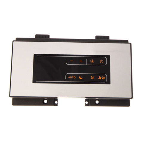
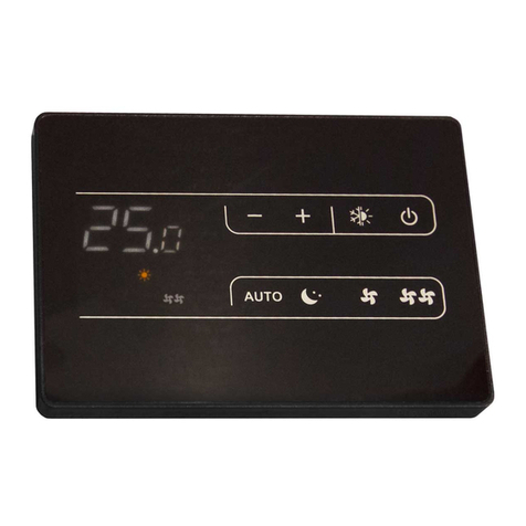
Control panel display
The control panel display shows the settings as changed by the user and the detected
weather conditions.
The backlit display is divided in areas.
1 On / off button and screensaver
2 Available icons 3 Function keys
1
2
3

6
GENERAL INFORMATION
Operating mode
Smart mode enabled
Cooling mode enabled
Heating mode enabled
Ventilation mode enabled
Dehumidification mode enabled
Functions
Access to the following functions is performed sequentially by pressing the key and work
on .
Vertical air deflector activated
Horizontal air deflector activated
Sleep function enabled
Heat Reclaim Ventilation function enabled
Not available
Energy Saving function on
Filter cleaning function enabled (visible in the cycle only when filter
cleaning is required)
Follow me function activated (available only for some models)
10 °C Anti-freeze function activated (available only for some models)
Health airflow
up Air flow upwards function (available only for some models)
Health airflow
down Air flow downwards function (available only for some models)

7
GENERAL INFORMATION
Other icons
(1) Display current time
(2) Alarm display
(1) Timer setting value
(2) Switch on timer enabled
(3) Switch off timer enabled
Cassette deflectors function enabled
(1) Detected ambient temperature
(2) Value of the desired temperature when pressing the increase and
decrease keys
Parental lock function activated
Lock function activated
Centralized control enabled
Not available
Fan speed set
Automatic speed enabled
Function keys
The control panel is equipped with touch function keys which can activate functions such
as choosing the operating mode, setting the desired temperature, timer and the motorized
deflector.
Allows you to switch the display off and on
Allow to select the operating mode
Decreases the value of the selected parameter
Increases the value of the selected parameter
Select required ventilation speed: superminimum (if available),
minimum, medium, maximum, maximum power (if available) or
automatic
Allows access to the timer settings and current time changing
Allows access to the functions

8
INSTALLATION
2
INSTALLATION
2.1
Receiving the product
The appliance is delivered in a single pack,
protected by cardboard packaging.
The following items can be found inside the
packaging:
Document envelope:
—Installer and user instruction booklet in
Italian
9
The Instruction book comes with the
equipment and it should be taken, read
and kept carefully.
9
The document envelope must be kept
in a safe place. Any duplicate must be
requested from Riello S.p.A. which re-
serves to charge the cost.
2.2
Dimensions and weight
PACKAGING
241
175
58
CONTROLS
86
86
2.3
Storage
9
The product must be stored of according
to the regulations in force.
2.4
Place of installation
The location of the device must be deter-
mined by the system's designer or by an-
other competent person, and must take into
account the technical requirements, as well
as any current local regulations.
The control panel is designed for indoor wall
installation.
1,5 m
OK

9
INSTALLATION
Check that:
—the position is about 1.5 m off the
ground
—installed taking into consideration the
maximum length of the connecting
cable.see the chapter "Electrical con-
nection"
Avoid:
—installation on a perimeter wall
—walls crossed by cold or hot piping
—installation near doors or windows,
cooking equipment, radiators, fan coils
or generally in conditions that might
alter the measured temperatures
—placing the unit less than 1 metre away
from radio and video systems
2.5
Positioning
The installation requires the positioning of
the control panel on the wall.
1 Touch panel
2 Base
—separate the device from base
—use the base as template
—mark fixing holes
—use a drill
—drill the wall
—use anchor bolts
1 Connection hole
1
CON1
A
B
C
—insert the connector through the con-
nection hole
—fix the base on the wall
—link the connector to the device
—hook the device to the base

10
INSTALLATION
2.7
Electrical connection
The appliance only needs to be connected to
the air conditioning system devices that are
being used.
Connection to system appliances
For sizing the signal cable, use the table be-
low:
Minimum
length
Maximum
length
Cable
diameter
m m mm² x n
0100 0,3 x 3
100 200 0,5 x 3
200 300 0,75 x 3
300 400 1,25 x 3
400 500 2 x 3
9
The connection is polarised, respect the
correct sequence.
9
Use a shielded double pole cable.
9
The connecting cable must be connected
to ground.
9
The connection cable must not have
joints; if these are required, they should
be tinned and suitably protected.
9
Any ducting of the connection cable
must be separated from voltage cables.
—make electrical connections according
to the diagrams below
1 Indoor unit
2 Wired Touch panel
A B C
A
1
2
B C
9
The connection is polarised, respect the
correct sequence.
Mandatory items:
—make sure that the electrical power
supply system is compliant with the
current national safety standards
—for any electrical intervention, always
refer to the wiring diagrams contained
within this booklet
—take anti-static precautions in case of
weather conditions where humidity is
less than 40%
9
Electric connections shall be made in
compliance with national regulations.
9
Avoid placing the connection cables less
than 1 metre away from radio and video
systems.
9
Avoid using mobile phones.
0 It is forbidden to earth the device to-
gether with pipes, lightning conductors
or the earthing system of a telephone
line. Using an improper earthing system
can cause electric shocks.

11
USE
3
USE
3.1
Initial settings
The control panel was designed to ensure
user-friendliness even with no special pro-
gramming.
To activate, just power on and set current
time.
3.1.1
Start-up
To switch on:
—press
The control display comes on and shows all
icons.
At the first commissioning and after the re-
set, the control panel performs an initializa-
tion procedure:
—the green LED flashes
The display shows the following icons in se-
quence:
—in the upper left corner
—
—in the upper right corner
Time setting
The current time must be set before using
the control panel:
—press for 5 seconds
9
At the first start up it's possible to set the
time until 10 seconds without press
.
—press to select minutes or hours
—work on
—set minutes and current time
Each time the key is pressed, the values
changes by 1. By keeping the key pressed
down, the value changes faster.
—confirm with
Abort:
—wait 10 seconds
Alternatively:
—press to cancel and turn off the
control panel
9
It is not possible to adjust the time dur-
ing the setting of the Timer and the Night
function.
3.2
Functions
Cooling mode
The Cooling mode allows starting and use of
the air conditioner as a producer of cold and
dehumidified air. To activate this function an
external temperature between +10 ° C and
46 ° C is recommended.
Required ambient temperature available
range is between 16 °C and 30 °C.
• Activation
—press in sequence until the
appears
Set required temperature as follows:
—work on
Value is stored with no need to press other
buttons.
• Switch-off
—select another operating mode
Alternatively:
—press to turn off the control panel
Heating Mode
The Heating mode allows starting and use of
the air conditioner as a hot air producer. To
activate this function an external tempera-
ture between -25 °C and 16 °C.

12
USE
Required ambient temperature available
range is between 16 °C and 30 °C.
Activation
—press in sequence until the
appears
Set required temperature as follows:
—work on
Value is stored with no need to press other
buttons.
• Switch-off
—select another operating mode
Alternatively:
—press to turn off the control panel
Dehumidification mode
Dehumidification mode allows starting and
using the system to reduce ambient humid-
ity.
Required ambient temperature available
range is between 16 °C and 30 °C.
The equipment will operate at displayed
ventilation speed. When the delta between
ambient temperature ad set temperature is
below two degrees, the equipment will op-
erate intermittently at the minimum ventila-
tion speed.
• Activation
—press in sequence until the
appears
Set required temperature as follows:
—work on
Value is stored with no need to press other
buttons.
• Switch-off
—select another operating mode
Alternatively:
—press to turn off the control panel
Ventilation mode
The Fan mode allows the user to turn on only
the fan, so as to recirculate and filter ambi-
ent air.
• Activation
—press in sequence until the
appears
9
The equipment will operate at selected
ventilation speed.
9
During operation in Ventilation mode,
automatic sped cannot be selected.
• Switch-off
—select another operating mode
Alternatively:
—press to turn off the control panel
Smart mode
In Automatic mode, equipment automati-
cally changes operating mode, toggling be-
tween Cooling and Heating to keep a con-
stant ambient temperature when outdoor
conditions change.
Temperature settings are preset.
—press in sequence until the
appears
Set required temperature as follows:
—work on
Value is stored with no need to press other
buttons.
• Switch-off
—select another operating mode
Alternatively:
—press to turn off the control panel
Adjusting ventilation speed
Ventilation speed can be adjusted in the fol-
lowing modes:
—Cooling
—Heating
—Dehumidification
—Ventilation

13
USE
A Super minimum Speed
B Minimum Speed
C Medium Speed
D Maximum Speed
E Super maximum Speed
F Automatic Speed
A
B
C
D
E
F
Set required ventilation speed as follows:
—work on
—Each press will select a different speed.
If selected , the speed changes auto-
matically according to preset strategies.
Maximum power speed and Supermax pow-
er forces equipment operation at maximum
to quickly achieve ambient required condi-
tions.
Hourly programming
Hourly programming allows user to set
equipment on and off times.
Switch-on occurs in the current operating
mode.
Automatic switch-on
Automatic switch-on programming allows
user to set equipment ON time.
9
Before activation, set current time.
• Activation
—press
—Control panel display shows .
• Set required time as follows:
—press to select hours or minutes
—work on
Each time the key is pressed, the values
changes by 1. By keeping the key pressed
down, the value changes faster.
—confirm with
• Abort:
—press or
• Alternatively:
—wait 10 seconds
• Switch-off
—press in sequence until all the in-
dications relative to the time program-
ming have disappeared
9
Programming remains active even when
control panel is off.
Automatic switch-off
Automatic switch-off programming allows
user to set equipment OFF time.
9
Before activation, set current time.
• Activation
—press in sequence until the
appears
• Set required time as follows:
—press to select hours or minutes
—work on
Each time the key is pressed, the values
changes by 1. By keeping the key pressed
down, the value changes faster.
—confirm with
• Abort:
—press or
• Alternatively:
—wait 10 seconds
• Switch-off
—press in sequence until all the in-
dications relative to the time program-

14
USE
ming have disappeared
Automatic start and stop (combined
function)
Timer functions can also be activated in
combination. Two configurations are avail-
able.
Timer on-off
The function is activated when the Timer on
is earlier than the Timer off.
Timer off-on
The function is activated when the Timer off
is earlier than the Timer on.
• Activation
—press in sequence until the
appears
• Set required time as follows:
—press to select hours or minutes
—work on
Each time the key is pressed, the values
changes by 1. By keeping the key pressed
down, the value changes faster.
—confirm with
• Abort:
—press or
• Alternatively:
—wait 10 seconds
• Switch-off
—press in sequence until all the in-
dications relative to the time program-
ming have disappeared
Horizontal motorised deflector
The horizontal motorised deflector controls
the vertical air flow by setting a preferred
outlet tilt or activating automatic operation.
Set required deflector position as follows:
• Activation
—press to enter the function cycle
—work on until the intermittent
appears
—press to confirm
The icon stay fixed.
• If the exit angle can be set:
—press to enter the function cycle
—work on until the intermittent
appears
—press
—work on
—select required position
Each press will select a different position.
—press to confirm
• Switch-off
—press to enter the function cycle
—work on until the intermittent
appears
—press to confirm
The icon disappears.
9
In environments with high humidi-
ty, condensation may form on the de-
flector during operation in Cooling and
Dehumidification mode. In this situa-
tion, if the deflector is kept in vertical
position for a long time, condensation
may fall on the objects below.
9
Do not set under the equipment any ob-
jects susceptible to get damaged in con-
tact with water.
9
When climate control system is turned
off, the horizontal deflector will close
automatically.
0 Do not manually move the deflector.
Vertical motorised deflector
The vertical motorised deflector controls the
horizontal air flow by setting a preferred out-
let tilt or activating automatic operation.
9
The Vertical Deflector is available on
some indoor unit models.

15
USE
Set required deflector position as follows:
• Activation
—press to enter the function cycle
—work on until the intermittent
appears
—press to confirm
The icon stay fixed.
• If the exit angle can be set:
—press to enter the function cycle
—work on until the intermittent
appears
—press
—work on
—select required position
Each press will select a different position.
—press to confirm
• Switch-off
—press to enter the function cycle
—work on until the intermittent
appears
—press to confirm
The icon disappears.
0 Do not manually move the deflector.
Sleep function
The Sleep function allows user to select a
time period throughout which the equip-
ment will change reference ambient tem-
perature:
—increasing it in Cooling and
Dehumidification mode
—decreasing it in Heating mode
9
In Smart mode: depending on the oper-
ating mode selected by the programme.
9
In the Sleep function, fan will decrease
its set speed by one.
• Activation
—press to enter the function cycle
—work on until the intermittent
appears
Control panel display shows with
the period of time.
• To set the time period:
—press
OFF icon starts blink.
—work on
—press to confirm
• Abort:
—press or
• Alternatively:
—wait 10 seconds
• Switch-off
9
The Auto Off Timer function can be set si-
multaneously with the Night function. In
this case the priority will be assigned to
the Auto Off Timer function.
9
The Auto On Timer function and the Night
function can not be set at the same time.
Energy Saving function
The appliance works by adopting energy
saving logics. The temperature setting values
are pre-setted by the program.
The Energy Saving function can be turned on
in the following modes:
—Heating
—Cooling
—Dehumidification
• Activation
—press to enter the function cycle
—work on until the intermittent
appears
—press to confirm
The icon stay fixed.

16
USE
• Switch-off
—press to enter the function cycle
—work on until the intermittent
appears
—press to confirm
The icon disappears.
9
Energy Saving function efficiency is high-
er after at least two hours of operation.
Anti-freeze function
In case of long periods away during winter
time, the Anti-freeze function maintains the
room at a temperature sufficient to avoid
freezing.
9
The Antifreeze function is visible in the
function cycle only in the Heating mode.
The Anti-freeze function can be turned on in
the following modes:
—Heating
• Activation
—press to enter the function cycle
—work on until appears writing "10
°C"
—press to confirm
The temperature value is fixed at 10 °C.
9
The equipment will operate at selected
ventilation speed.
9
The equipment will operate to keep
room temperature at 10 °C.
• Switch-off
—press to enter the function cycle
—work on until appears writing "10
°C"
—press to confirm
The temperature value is not fixed at 10 °C
and it is possible to change.
Parental lock function
Prevent any accidental control by locking re-
mote control buttons.
• Button locking
—press + simultaneously for 5
seconds
Remote control display shows .
• Button unlocking
—press + simultaneously for 5
seconds
disappears in the display of the remote
control
Screensaver function
The screensaver function allows the display
to be switched off when not required for
carrying out the operations, providing ener-
gy savings.
The time after which the screen saver starts
can be set between: 15, 30, 60 seconds.
Factory setting value is 15 seconds.
9
By setting the value to 0 seconds, the
display is always on.
• Activation:
—press and simultaneously for 5
seconds
—work on
—confirm with
• To cancel:
—press
Selecting the temperature
measurement unit
If required, it is possible to change the tem-
perature measurement unit.
The available units are:
—Celsius °C
—Fahrenheit °F
• It switches the temperature scale from
Celsius to Fahrenheit:
—set temperature 30° in each operating

17
USE
mode
—press for 15 seconds
It switches the temperature scale from
Fahrenheit to Celsius:
—set temperature 30° in each operating
mode
—press for 15 seconds

18
RECYCLING AND DISPOSAL
4
DISPOSAL
Packing materials must be disposed of sepa-
rately, in order to be recovered and recycled.
Equipment at end of life and flat batteries
must be disposed of as required by prevail-
ing law and regulations.


RIELLO S.p.A. - 37045 Legnago (VR)
tel. +39 0442 630111 - fax +39 0442 630371
www.riello.it
As the manufacturer is constantly improving its products, the aesthetic or dimen-
sional features, the technical data, the equipment and accessories indicated could
be subject to variations.
Table of contents
Other Riello Control Panel manuals

Riello
Riello 20147241 User manual

Riello
Riello RIELLOtech PRIME User manual

Riello
Riello RIELLOtech CLIMA TOP User manual

Riello
Riello Thermital TBOX BASIC ACS Technical manual

Riello
Riello CPD 35 User manual

Riello
Riello NexSirius User manual

Riello
Riello Touchscreen N User manual

Riello
Riello CBD 35 User manual

Riello
Riello 4030011 User manual

Riello
Riello CPD 30 User manual
Popular Control Panel manuals by other brands

Entrematic
Entrematic LCU40H installation manual

wattstopper
wattstopper Legrand Miro MRDS10 quick start guide

Scantronic
Scantronic 808 user guide

Paradox
Paradox IMPERIAL K651 User quick reference guide

Paradox
Paradox MG5000 Programming guide

AutomationDirect
AutomationDirect C-more EA1-T4CL Hardware user manual