Teleorigin RB900 User manual

1

Contents
1. Overview............................................................................................................................5
2. References.........................................................................................................................6
3. Package.............................................................................................................................7
3.1 Box......................................................................................................................................... 7
4. Comple e package con en s..............................................................................................8
5. General presen a ion.........................................................................................................9
5.1 Produc pic ures ....................................................................................................................9
5.2 Ex ernal connec ions............................................................................................................10
5.2.1 GSM an enna connec or................................................................................................10
5.2.2 GPS an enna connec or................................................................................................10
5.2.3 Memory slo ...................................................................................................................11
5.2.4 USB In erface.................................................................................................................11
5.2.5 RS-232 In erface (EIA574)............................................................................................12
5.2.6 RS-485 in erface........................................................................................................... 13
5.2.7 D-Sub HD 15-pin connec or...........................................................................................14
5.2.8 Power supply connec or................................................................................................15
5.2.9 SIM card holder............................................................................................................. 15
5.3 Produc s icker.................................................................................................................... 16
6. Basic fea ures and services.............................................................................................17
7. Using he modem.............................................................................................................18
7.1 Se ing up he modem...........................................................................................................18
7.2 Moun ing he modem...........................................................................................................19
7.2.1 On DIN bus.................................................................................................................... 19
7.2.2 On he wall.....................................................................................................................20
7.3 Checking he communica ion wi h he modem.....................................................................20
7.4 S a us of he modem (LEDs)................................................................................................21
7.5 Disabling and enabling echo func ion...................................................................................21
7.6 Verifying he s reng h of received signal...............................................................................22
7.7 PIN code s a us................................................................................................................... 22
7.8 Ne work regis ra ion..............................................................................................................23
7.8.1 GSM ne work regis ra ion..............................................................................................23
7.9 GPRS ne work regis ra ion...................................................................................................24
7.10 AT commands summary.....................................................................................................25
8. Troubleshoo ing................................................................................................................26
2

8.1 No connec ion/communica ion wi h he modem....................................................................26
8.2 Receiving ERROR message................................................................................................26
8.3 Receiving NO CARRIER message.......................................................................................27
9. Technical charac eris ics..................................................................................................28
9.1 Mechanical charac eris ic.....................................................................................................28
9.2 Housing descrip ion (dimensioning diagram)........................................................................28
10. Elec rical charac eris ic..................................................................................................29
10.1 Power supply......................................................................................................................29
10.2 RF charac eris ics...............................................................................................................29
10.3 Ex ernal an enna................................................................................................................ 31
10.4 Environmen al charac eris ic...............................................................................................31
11. Py hon Scrip In erpre er................................................................................................32
12. AppZone.........................................................................................................................34
13. RB900-GPS...................................................................................................................35
14. RB900MODBUS............................................................................................................36
15. AT Reference manual.....................................................................................................37
16. Safe y recommenda ions...............................................................................................46
16.1 General Safe y....................................................................................................................46
16.2 Care and Main enance.......................................................................................................46
16.3 Responsibili y..................................................................................................................... 46
17. Accessories....................................................................................................................47
17.1 Accessories cri ical for using modem..................................................................................47
17.2 Addi ional accessories........................................................................................................48
18. Conformi y Assessmen Issues......................................................................................49
19. Safe y Recommenda ions..............................................................................................50
20. Lis of Acronyms.............................................................................................................51
21. On-line suppor ...............................................................................................................53
3

APPLICABILITY TABLE
Modem Short description
RB900 Basic GPRS modem
RB900-IO GPRS modem wi h GPIO signals
RB900-M GPRS modem wi h memory card connec or
RB900-GPS GPRS modem wi h GPS/Glonass receiver
RB900MODBUS GPRS modem wi h Modbus applica ion
RB900U Basic UMTS modem
RB900U-IO UMTS modem wi h GPIO signals
RB900U-M UMTS modem wi h memory card connec or
RB900U-GPS UMTS modem wi h GPS/Glonass receiver
RB900L Basic LTE modem
4

1. Overview
The RB900 Terminal is he comple e modem solu ion for wireless m2m applica ions.
Based on he Teli GE910, HE910 or LE910 module, i is available as pen a or quad-band
version and offers high level GSM/GPRS/HSPA+/LTE fea ures in compac aluminium
housing wi h all he s andardized in erfaces and op ionally GPS receiver, configurable
GPIO or memory card o s ore all measured da a. Toge her wi h i s small size and wide
supply vol age range, makes i easy o in egra e in o all kinds of machines.
The RB900 erminal enabling voice, high speed da a ransmission, SMS and fax
communica ion is a universal solu ion for all low-volume M2M and mobile da a applica ions
including me ering, raffic sys ems, ranspor a ion and logis ics, securi y, vending
machines, and facili y managemen .
Device can be con rolled by s andard AT commands or by cus omer's applica ion inside
(embedded Py hon Scrip In erpre er or “C” language), hus making i he smalles ,
comple e SMT pla form for m2m solu ions.
This documen con ains full RB900 modem descrip ion and gives informa ion abou
ins alla ion and using i .
5

2. References
[1] Teli _AT_Commands_Reference_Guide.pdf
[2] Teli _HE910_UE910_UL865_AT_Commands_Reference_Guide.pdf
[3] Teli _LE910_AT_Commands_Reference_Guide.pdf
[4] Teli _GE910_Produc _Descrip ion.pdf
[5 Teli _HE910-Family_Produc _Descrip ion.pdf
[6] Teli _LE910_Produc _Descrip ion.pdf
[7] Teli _Easy_Scrip _Py hon_2.7.pdf
[8] GE910_AppZone_API_User_Guide.chm
[9] h p://www.py hon.org/
6

3. Package
3.1 Box
Original box of he produc is shown in he pic ure below.
We can find produc s icker on he box. I ma ches modems s icker ha is placed on he
device. This proves ha your modem is original produc . More informa ion abou s ickers
in chap er 5.3.
7
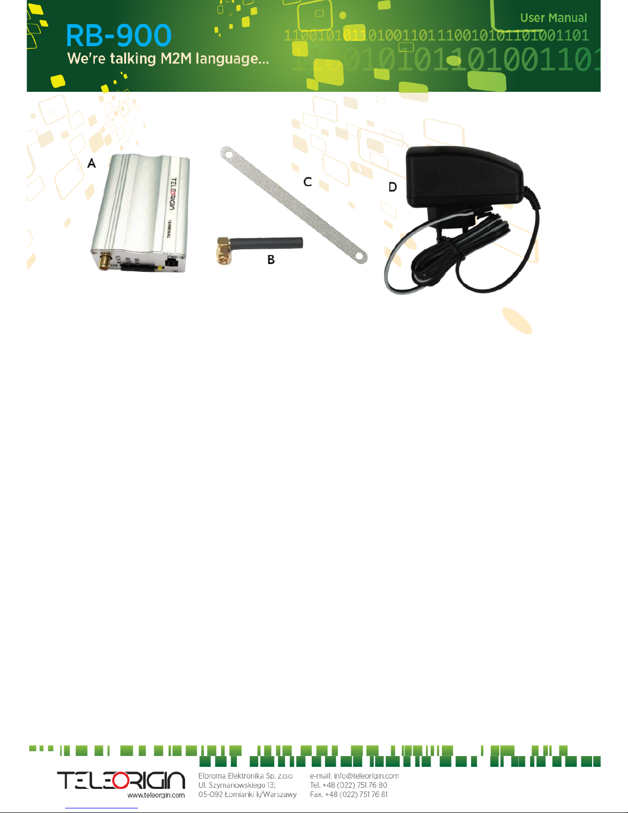
. Complete package contents
Comple e package con ains:
•RB900 erminal (i em A)
•GSM an enna (via SMA) (i em B)
•wall handle (i em C)
•power adap or (i em D)
8

5. General presentation
5.1 Product pictures
9
SMA
connector
Extractable
SIM card
holder
SIM card
holder
ejector
Power
supply
EIA574 (RS- 3 )
DE9 D-sub socket
USB
DATA
GSM
PWR
LED's

5.2 External connections
5.2.1 GSM antenna connector
SMA “ANT” inpu is used o connec ex ernal GSM an enna. To es ablish connec ion
wi h GSM ne work an ex ernal an enna mus be used. Type of an enna depends on GSM
coverage. In good circums ances (level of received signal is high) use an enna which is
a ached in he package. If range of GSM is low or none, an ou door or indoor (for ins ance
in place where GSM range is sufficien ) an enna should be used.
Note: If there is no antenna connected to SMA connector, the connection with GSM
network is impossible.
5.2.2 GPS antenna connector
SMA “GPS” inpu is used o connec ex ernal GPS an enna. To es ablish connec ion
wi h GPS sa eli es and check he coordina es of device an ex ernal an enna mus be used
and should be loca ed ou door.
10
Other manuals for RB900
1
This manual suits for next models
9
Table of contents
Other Teleorigin Modem manuals


