Teleorigin RB900 User manual
1

Contents
1. Overview............................................................................................................................5
2. References.........................................................................................................................6
3. Product variants.................................................................................................................7
4.Package..............................................................................................................................8
4.1 Box......................................................................................................................................... 8
5. omplete package contents..............................................................................................9
6. General presentation.......................................................................................................10
6.1 Product pictures .................................................................................................................. 10
6.2 External connections.............................................................................................................11
6.2.1 GSM antenna connector................................................................................................11
6.2.2 GPS antenna connector.................................................................................................11
6.2.3 Memory slot...................................................................................................................12
6.2.4 USB Interface................................................................................................................12
6.2.5 RS232 Interface (EIA574).............................................................................................13
6.2.6 RS485 interface............................................................................................................14
6.2.7 D-Sub HD 15-pin connector...........................................................................................15
6.2.8 Power supply connector................................................................................................17
6.2.9 SIM card holder.............................................................................................................17
6.3 Product sticker....................................................................................................................18
7. Basic features and services.............................................................................................19
8. Using the modem.............................................................................................................20
8.1 Setting up the modem...........................................................................................................20
8.2 Mounting the modem...........................................................................................................21
8.2.1 On DIN bus....................................................................................................................21
8.2.2 On the wall.....................................................................................................................22
8.3 hecking the communication with the modem.....................................................................22
8.4 Status of the modem (LEDs)................................................................................................23
8.5 Disabling and enabling echo function...................................................................................23
8.6 Verifying the strength of received signal...............................................................................24
8.7 PIN code status................................................................................................................... 24
8.8 Network registration..............................................................................................................25
8.8.1 GSM network registration..............................................................................................25
8.9 GPRS network registration...................................................................................................26
8.10 AT commands summary.....................................................................................................27
2

9. Troubleshooting................................................................................................................28
9.1 No connection/communication with the modem....................................................................28
9.2 Receiving ERROR message................................................................................................28
9.3 Receiving NO ARRIER message.......................................................................................29
10. Technical characteristics................................................................................................30
10.1 Mechanical characteristic...................................................................................................30
10.2 Housing description (dimensioning diagram)......................................................................30
11. Electrical characteristic...................................................................................................31
11.1 Power supply...................................................................................................................... 31
11.2 RF characteristics...............................................................................................................31
11.3 External antenna.................................................................................................................33
11.4 Environmental characteristic...............................................................................................33
12. Python Script Interpreter................................................................................................34
13. AppZone.........................................................................................................................36
14. RB900-GPS...................................................................................................................37
15. RB900MODBUS............................................................................................................38
16. AT Reference manual.....................................................................................................39
17. Safety recommendations...............................................................................................43
17.1 General Safety....................................................................................................................43
17.2 are and Maintenance.......................................................................................................43
17.3 Responsibility.....................................................................................................................43
18. Accessories....................................................................................................................44
18.1 Accessories critical for using modem..................................................................................44
18.2 Additional accessories........................................................................................................45
19. onformity Assessment Issues......................................................................................46
20. Safety Recommendations..............................................................................................47
21. ertifications..................................................................................................................49
22. List of Acronyms.............................................................................................................51
23. Online support................................................................................................................53
3
APPLI ABILITY TABLE
Modem Short description
RB900 Basic GPRS modem
RB900-IO GPRS modem with GPIO signals
RB900-M GPRS modem with memory card connector
RB900-GPS GPRS modem with GPS/Glonass receiver
RB900MODBUS GPRS modem with Modbus application
RB900U Basic UMTS modem
RB900U-IO UMTS modem with GPIO signals
RB900U-M UMTS modem with memory card connector
RB900U-GPS UMTS modem with GPS/Glonass receiver
RB900L Basic LTE modem
4

1. Overview
The RB900 Terminal is the complete modem solution for wireless m2m applications.
Based on the Telit GE910, HE910 or LE910 module, it is available as penta or quad-band
versions and offers high level GSM/GPRS/HSPA+/LTE features in a compact aluminium
housing with all the standardized interfaces and optional GPS receiver, configurable GPIO
or memory card to store all the measured data. Together with its small size and wide
supply voltage range, it is easy to integrate into all kinds of machines.
The RB900 terminal enabling high speed data transmission, SMS and T P/IP
communication is a universal solution for all low-volume M2M and mobile data applications
including metering, traffic systems, transportation and logistics, security, vending
machines, and facility management.
The device can be controlled by standard AT commands or by customer's own
application inside (embedded Python Script Interpreter or “ ” language), thus making it the
smallest, complete SMT platform for m2m solutions.
This document contains full RB900 modem description and gives information about
installation and using it.
5

2. References
[1] Telit_AT_ ommands_Reference_Guide.pdf
[2] Telit_3G_Modules_AT_ ommands_Reference_Guide.pdf
[3] Telit_LE9x0_AT_ ommands_Reference_Guide.pdf
[4] Telit_GE910_Product_Description.pdf
[5] Telit_HE910-Series_Product_Description.pdf
[6] Telit_LE910_Product_Description.pdf
[7] Telit_Easy_Script_Python.pdf
[8] Telit_Easy_Script_Python_2.7.pdf
[9] Telit_IoT_AppZone _API_Reference Guide.pdf
[10] http://www.python.org/
6

3. Product variants
RB900 modem variants, order codes and its description are listed below.
Example:
RB900 .IO.X.X.X.1 – HSPA+ modem with RS232 and IO connector, 1 SIM holder, with
DIN rail mounting kit
7
RB900 .....
X - GE910
U - HE910
L - LE910
XM -
UM -
LM -
X - standard
IO -
I -
O -
GPS
IO GPS -
X - 1SIM
2 - 2SIM
X - RS232
2 - RS232+RS485
X - standard
X - standard:
1 -
Special Sof tweare
Special Option
GE910+MicroSD
HE910+MicroSD
LE910+MicroSD
option GPIO
only INPUT
only OUTPUT
option GPS
option IO + GPS
- power supply
- antenna
- wall mount kit
Standard + DIN rail mounting kit


5. Complete package contents
omplete package contains:
•RB900 terminal (item A)
•GSM antenna (SMA connector) (item B)
•wall bracket (item )
•power adaptor (item D)
9
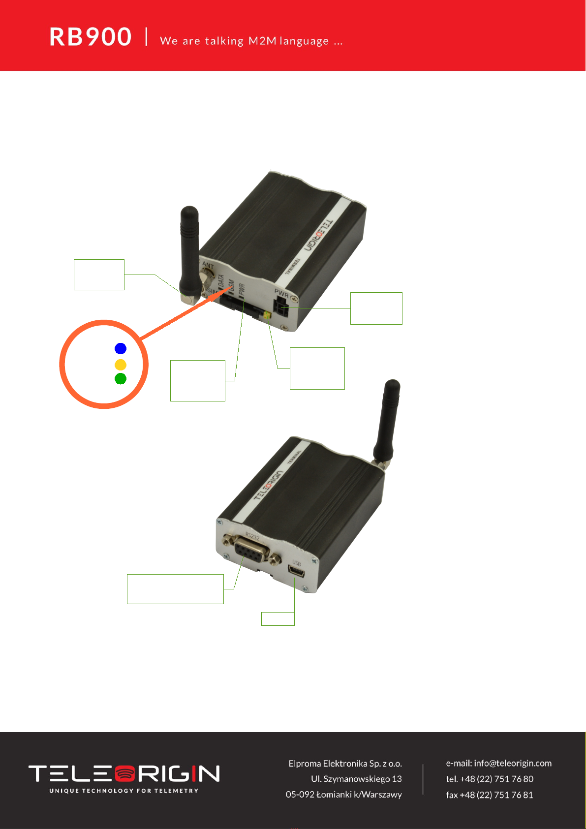
6. General presentation
6.1 Product pictures
10
SMA
connector
Extractable
SIM card
holder
SIM card
holder
ejector
Power
supply
EIA574 (RS- 3 )
DE9 D-sub socket
USB
DATA
GSM
PWR
LED's
Other manuals for RB900
1
This manual suits for next models
10
Table of contents
Other Teleorigin Modem manuals


