Teleorigin RB900SG User manual

1

Contents
1. Overview............................................................................................................................5
2. Product variants.................................................................................................................6
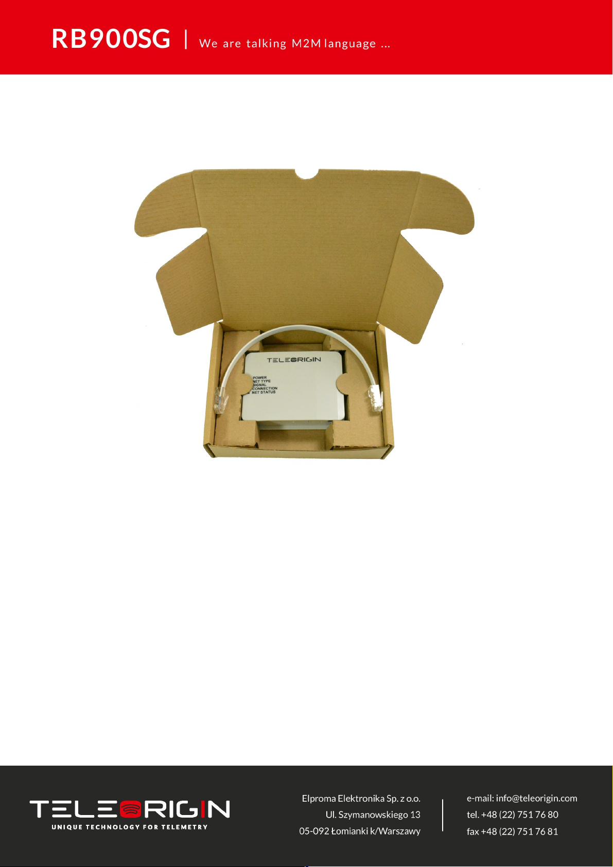
3. Complete package contents..............................................................................................7
4. General presentation.........................................................................................................
4.1 Product pictures ....................................................................................................................
4.2 External connections..............................................................................................................9
4.2.1GSM antenna connector...................................................................................................9
4.2.2GNSS antenna connector.................................................................................................9
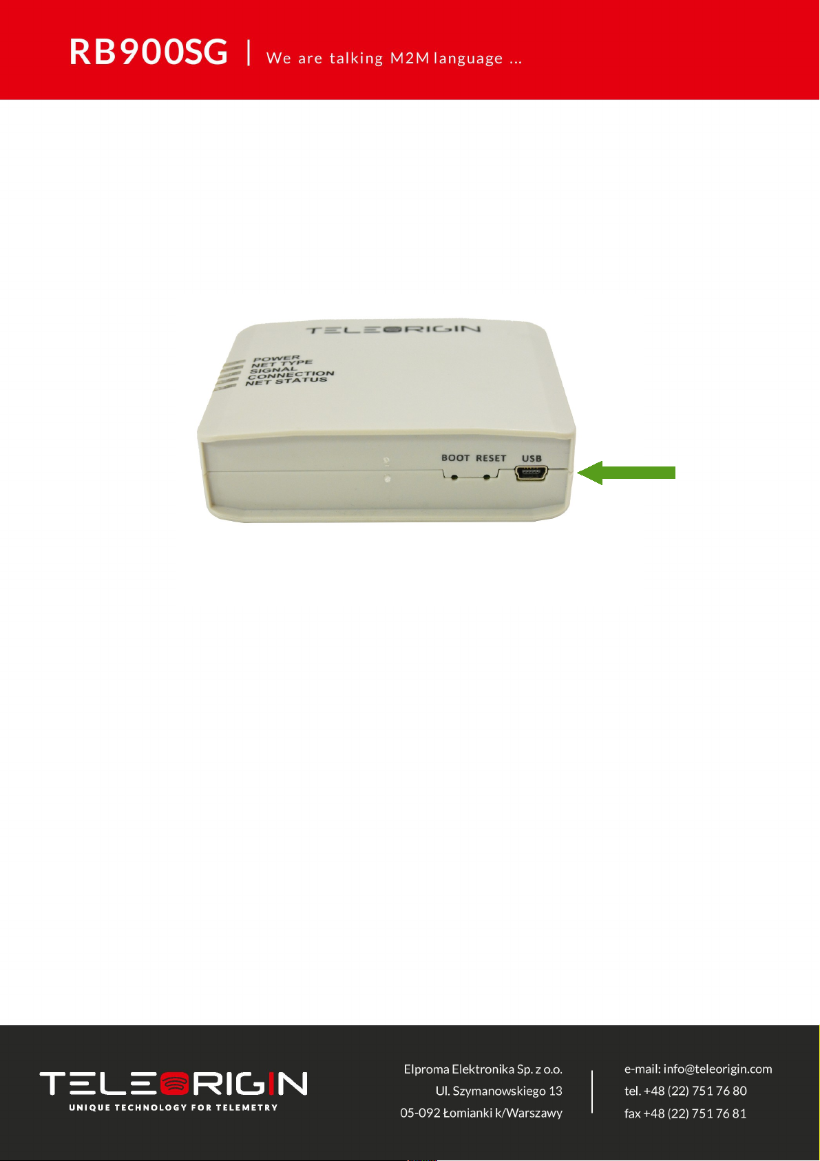
4.2.3 USB Interface................................................................................................................10
4.2.4 RS232/RS4 5/RS422 interfaces....................................................................................11
4.2.5 Power supply connector................................................................................................12
4.2.6 SIM card holder.............................................................................................................13
4.3 Product sticker......................................................................................................................14
5. Basic features and services.............................................................................................15
6. Using the modem.............................................................................................................16
6.1 Setting up the modem...........................................................................................................16
6.2 Mounting the modem............................................................................................................20
6.3 Checking the communication with the modem......................................................................21
6.4 Status of the modem (LEDs)................................................................................................22
6.5 RESET and BOOT buttons...................................................................................................22
7. Troubleshooting................................................................................................................23
7.1 No connection/communication with the modem....................................................................23
. Technical specifications....................................................................................................24
.1 Mechanical specifications.....................................................................................................24
.2 Housing description (dimension diagram).............................................................................24
9. Electrical specification......................................................................................................25
9.1 Power supply........................................................................................................................ 25
9.2 RF specifications..................................................................................................................25
9.3 External antenna.................................................................................................................. 31
9.4 Environmental characteristic.................................................................................................31
10. Safety recommendations...............................................................................................32
10.1 General Safety....................................................................................................................32
10.2 Care and Maintenance.......................................................................................................32
10.3 Responsibility.....................................................................................................................32
2

11. Accessories....................................................................................................................33
12. Conformity Assessment Issues......................................................................................34
13. Safety Recommendations..............................................................................................35
14. List of Acronyms.............................................................................................................37
15. Online support................................................................................................................39
3

APPLICABILITY TABLE
Modem Short description
RB900SG-L2 2G+LTE Cat. M1 + LTE Cat. NB1 modem version
RB900SG-L5 2G+LTE Cat. M1 + LTE Cat. NB2 modem version
RB900SG-E5 4G Cat. 4 modem version
RB900SG-E1 4G Cat. 1 modem version
RB900SG-U6 3G Global modem version
RB900SG-U5 3G Dual band modem version
4

1. Overview
The RB900SG Terminal is the complete modem solution for wireless m2m applications.
It offers high level LPWA/2G/3G/4G features and RS232/4 5/422 communication
interfaces and USB interface for configuration. Together with its small size and wide power
supply range, it is easy to integrate it with energy meters.
The RB900SG terminal enabling high speed data transmission, SMS and TCP/IP
communication. The device can be controlled by standard AT commands and configured
by RB-Setup application, thus making it the complete SMT platform for m2m solutions.
This document contains full RB900SG modem description and gives information about
installation and using it.
5

2. Product variants
RB900SG modem variants and its description are listed below.
Model Description
RB900SG-U5.X.X.2.X.X Dual band 3G modem
RB900SG-U6.X.X.2.X.X Quad band 3G modem
RB900SG-E1.X.X.2.X.X LTE Cat. 1 modem
RB900SG-E5.X.X.2.X.X LTE Cat. 4 modem
RB900SG-L2.X.X.2.X.X 2G/LTE Cat. M1 & NB1 modem
RB900SG-L5.X.X.2.X.X 2G/LTE Cat. M1 & NB2 modem
It is possible to use SIM-CHIP solution. Example P/N of the modem with SIM-CHIP:
RB900SG- 2.X.C.2.X.X – 2G/LTE Cat. M1 & NB1 modem with SIM-CHIP
6

3. Complete package contents
Complete package contains:
•RB900SG modem (item A)
•RJ45 cable (item B)
7
AA
B

4. General presentation
4.1 Product pictures
SMA
connector
Extractable
SIM card
holder
SIM card
holder
ejector
Power
supply
RESET button
USB
POWER
ET TYPE
SIG AL
CO ECTIO
ET STATUS
LED's
Power
supply
BOOT button

4.2 External connections
4.2.1 GSM antenna connector
An SMA “ANT” input is used to connect external GSM/UMTS/LTE antenna. To establish
a connection with a GSM/UMTS/LTE network, an external antenna must be used. Type of
antenna depends of GSM/UMTS/LTE coverage. In good circumstances (level of received
signal is high) use antenna contained in the package. If the range of GSM/UMTS/LTE is
low or none, an outdoor or indoor (for instance in place where GSM/UMTS/LTE range is
sufficient) antenna should be used.
Note: If there is no antenna connected to SMA connector, the connection with
GSM/UMTS/LTE network is impossible.
4.2.2 GNSS antenna connector
An SMA “GNSS” input is used to connect an external GPS/Glonass antenna. To
establish connection with GPS/Glonass sattelites and check the coordinates of the device,
an external antenna must be used and should be located outdoors. GNSS is optionally
available in RB900SG-L2 and RB900SG-L5 modem variants.
9

4.2.3 USB Interface
RB900SG terminal is equipped with a USB interface (as shown below). Type of
connector is miniUSB. It is used for device configuration.
10

4.2.4 RS232/RS485/RS422 interfaces
The RB900SG terminal is equipped with RS232/RS4 5/RS422 interfaces in RJ45
socket. Use the jumper to switch between interfaces. All available jumper positions are
presented in 7.1. Setting up the modem
Table of RJ45 serial connector:
Connector RJ6 RJ6 RJ6 RJ1 RJ4 RJ2 RJ5 RJ7
RS232 GND GND GND VCC RJ5 RJ7 RJ4 RJ2
RS4 5 GND GND GND VCC TX - RX DTR
RS422 GND GND GND VCC TX+ TX- RX+ RX-
11

4.2.5 Power supply connector
The power supply connector is a 2-pin connector for external DC power supply
connection, which can handle voltage from range 5..30 V DC, 2.5 W max. continuous
power.
No. Singal I/O Description
+ V+BATTERY I 5 V – 30 V DC
- GND - Ground
Attention!
An attempt to power terminal from a DC source outside of 5..30 V range may result in the
physical destruction of the device.
12

4.2.6 SIM card holder
A SIM card holder is placed at the front of the RB900SG terminal (as shown below), and
is accessible externally. To insert a SIM card into the holder, press the yellow button,
eject the little drawer, place the SIM card inside and insert drawer into the modem (you will
hear „click”). To operate the module in a GSM/UMTS/LTE/LPWA network, it is necessary to
insert a SIM card obtained from the network operator.
13

4.3 Product sticker
Product stickers are on the modem and on the box of the product. They includes the
following informations and markings:
•product serial number (IMEI)
•model signature
•CE marking
•15-digit bar code
•manufacturer address
Device sticker Box sticker
14

5. Basic features and services
Basic features and available services for RB900SG are contained in table below.
Feature/service Description
Standard
Supported Bands:
RB900SG-L2:
•Cat M1/Cat NB1: LTE FDD: B1/B2/B3/B4/B5/B /B12/B13/B1 /B19/B20/B26/B2
•LTE TDD: B39 (For Cat M1 Only)
•EGPRS: 50/900/1 00/1900MHz
RB900SG-L5:
•LTE Cat M1/Cat NB2/EGPRS
RB900SG-E5:
•LTE FDD: B1/B3/B7/B /B20/B2 A
•WCDMA: B1/B
•GSM: 900/1 00MHz
RB900SG-E1:
•LTE FDD: B1/B3/B7/B /B20/B2 A*
•WCDMA: B1/B
•GSM: 900/1 00MHz
RB900SG-U6:
•00/ 50/900/1900/2100MHz @UMTS
•50/900/1 00/1900MHz @GSM
RB900SG-U5:
•900/2100MHz@UMTS
•900/1 00MHz@GSM
Physical:
•100 x 70 x 27 mm
•Weight 170 g
Interfaces
Connectors
•SMA for GSM antenna
•SMA for GPS antenna (option)
SIM Card
•3.0V / 1. V
•STK 3.1
Connectivity
•RS232/4 5/422
•USB 2.0 HS (configuration)
SMS MO/MT Text and PDU mode
GSM/ TE supplementary
services
TCP/IP
Power supply 5V – 30V DC
15

6. Using the modem
6.1 Setting up the modem
To set up the modem, follow these steps:
•Eject SIM card holder using yellow button and pull out the drawer.
16
1
2

•Insert your SIM card into drawer.
•Verify if SIM card fits in the drawer properly (as shown below).
•Insert the drawer into the modem.
17

•Insert a jumper to one of the connector to set the right serial port. Possible jumper positions
are described in a picture below
1
RS422
RS232
RS485

•Plug the power supply cable into the power supply input
•Connect the modem using RS232/RS4 5/RS232 RJ45 cable to meter or miniUSB cable to PC
with configuration software
•Now the modem is ready to work.
19

6.2 Mounting the modem
To mount the modem inside the meter housing, please use one of the handles.
20
Other manuals for RB900SG
2
Table of contents
Other Teleorigin Modem manuals