© 2009 Bosch Security Systems, Inc.
130 Perinton Parkway, Fairport, NY 14450-9199 USA
(800) 289-0096
F01U126801-01
Installation Guide
3/0
ISW-EN126
Page 2 of
4.0 Register the Transmitter
To ensure that the detector is supervised by the system receiver,
you must register its transmitter with the system receiver. Each
detector has a unique factory-programmed identification number.
Refer to the receiver, network coordinator or control panel
installation instructions for details on registering a transmitter.
1. If necessary, remove the housing cover.
2. When prompted to reset the detector, press the Reset button
on the detector.
3. Replace the housing cover.
To ensure correct operation, test the detector after it
is registered with the system receiver. To test the
detector, activate each of the conditions and ensure
that an appropriate response occurs.
5.0 Mount the Detector
1. Install the housing cover.
2. Remove the mounting bracket.
Refer to Figure 1, page 1.
3. Mount the housing base to the ceiling using the supplied
anchors and screws.
The maximum mounting height for the detector is
3.6 m (12 ft). As mounting height increases, distance
between detection zones also increases toward the
perimeter, thus intensifying the effects of factors such
as floor surface temperature, and intruder direction
and speed. These effects can ultimately reduce
detection speed.
Ensure that a walk test is performed to check all
detection zones, including the intrusion paths
crossing the edges of the zones.
Refer to Figure 3 and Figure 4 for more information.
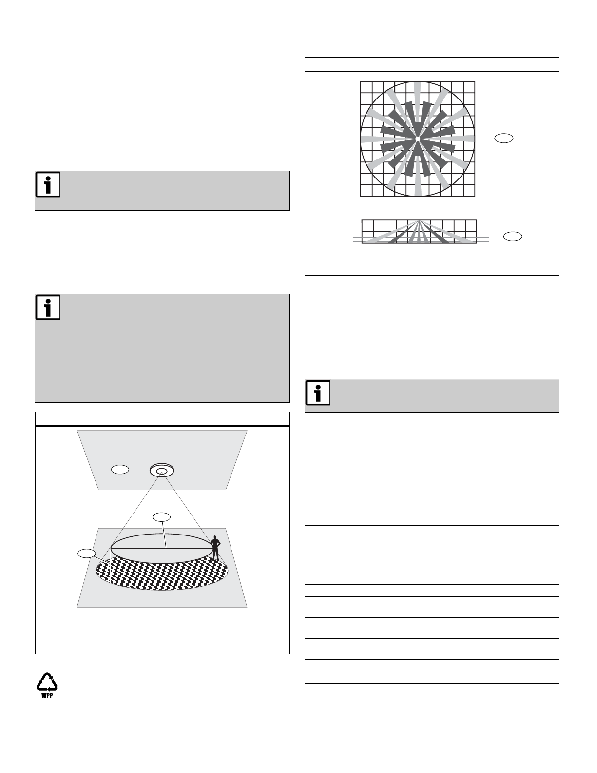
Figure 3: Detection Diameter
1
3
2
1 - Ceiling mounting height: 10 ft (3 m)
2 - Effective detection diameter: 46 ft (14 m)
3 - Distance between detection diameter and floor: 2.6 ft
(0.8 m)
Figure 4: Lens Pattern
1
2
0 m
0 m
2 m
2 m
2 m
4 m
4 m
4 m
6 m
6 m
6 m
0 ft
13.1 ft
8 m 10 m
6 m
13.1 ft 26.2 ft
32.8 ft
10 m
8 m
4 m 2 m
26.2 ft 13.1 ft
26.2 ft
8 m10 m
13.1 ft
32.8 ft
26.2 ft
32.8 ft
8 m
10 m
32.8 ft
0 ft
0 m
0 m
2 m
2 m
4 m
4 m
6 m
13.1 ft
8 m 10 m
6 m
13.1 ft 26.2 ft
32.8 ft
4 m 2 m
26.2 ft 13.1 ft
8 m10 m
32.8 ft
0 ft
0 ft
12 ft
3.65 m
3 m
2.4 m 8 ft
10 ft
1 - Top view
2 - Side view
6.0 Test the Detector
6.1 Perform a One-Minute Walk Test
To start a one-minute walk test:
•Remove the cover, and hold a magnet near the test reed switch
for 1 sec, or
•Press and hold the test button for 1 sec.
During the walk test period, the detector does not send alarm
signals, and the test LED blinks each time the detector senses
motion.
The test LED (refer to Figure 2, page 1) blinks only
during a walk test or transmission test.
6.2 Perform a Transmission Test
To start a transmission test:
•Remove the cover, and hold a magnet near the Test Reed
switch for at least 3 sec, or
•Press and hold the Test button for at least 3 sec.
During the transmission test, the detector sends alarm and restoral
signals at regular intervals for approximately one minute. The LED
blinks each time the unit sends a signal. Ensure that events are
received by your network coordinator, receiver or control panel.
7.0 Specifications
Dimensions (H x W): 131 cm x 57 cm (5.2 in. x 2.25 in.)
Weight: 185 g (6.52 oz)
Detection Method: Four-element PIR
Operating Temperature: 0°C to +49°C (+32°F to +120°F)
Humidity: 10% to 90% (non-condensing)
Battery: 3 V lithium (DL123A)
Typical Battery Life: 4 years in a location with low-to-
moderate activity
Visible Light Protection: Stable against halogen light 2.4 m
(8 ft) or reflected light
Temperature
Compensation:
Yes
Pulse Count: Single or multiple pulse
Standard Lens Coverage: 20 m (65.6 ft) x 360∞


