Televes CoaxManager User manual

CoaxManager™
User Guide

Content Index
Important safety instructions.................................................................................................................... 4
General installation conditions.....................................................................................................................4
How to use the equipment safely.................................................................................................................4
Electrical safety symbols..............................................................................................................................4
Introduction............................................................................................................................................... 5
Application Description................................................................................................................................ 5
Features.......................................................................................................................................................5
System Requirements .................................................................................................................................5
Supported CoaxDATA Devices.................................................................................................................... 5
Installing CoaxManager Application......................................................................................................... 6
Connecting CoaxDATA Modem to CoaxManager .......................................................................................7
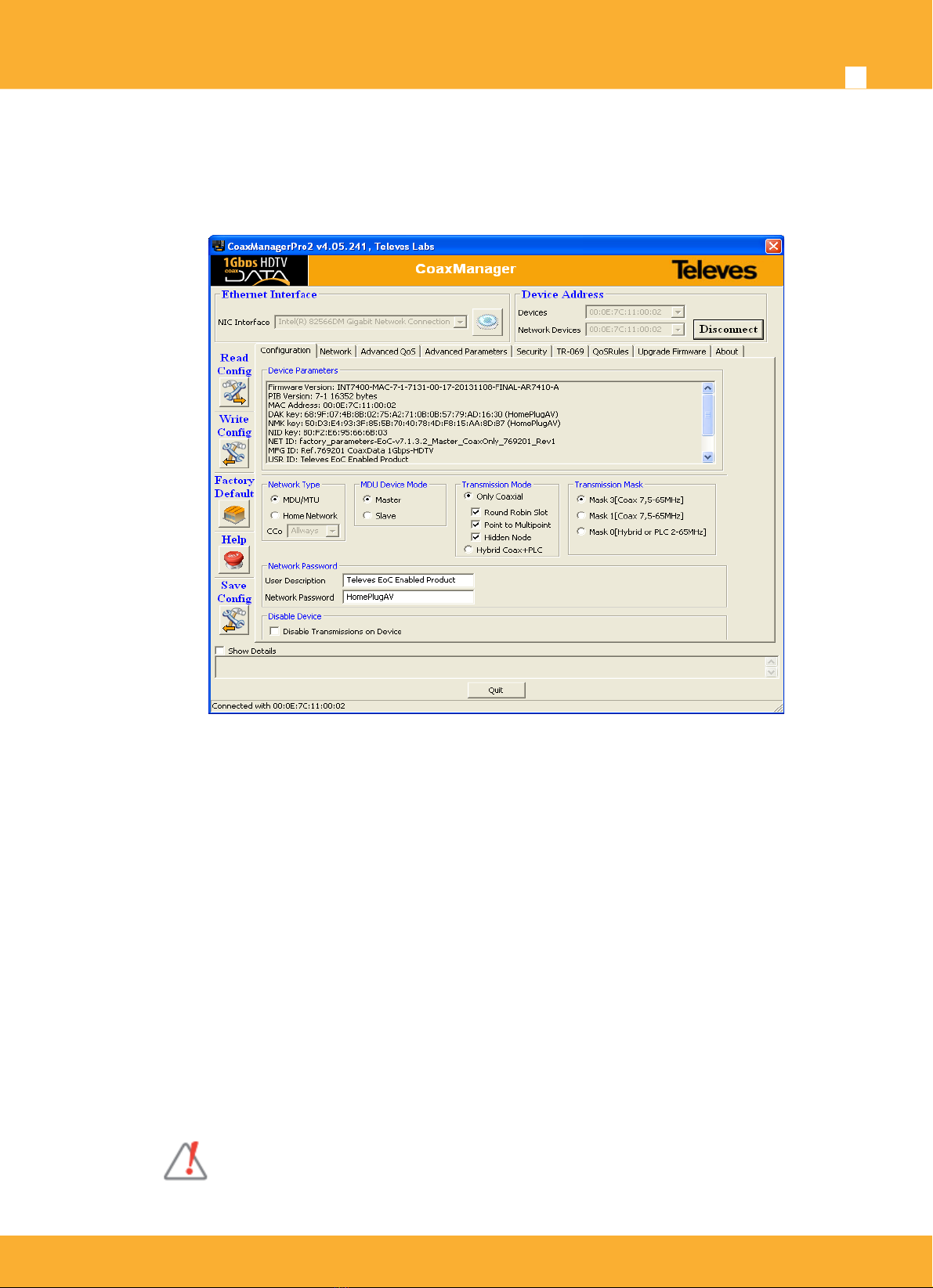
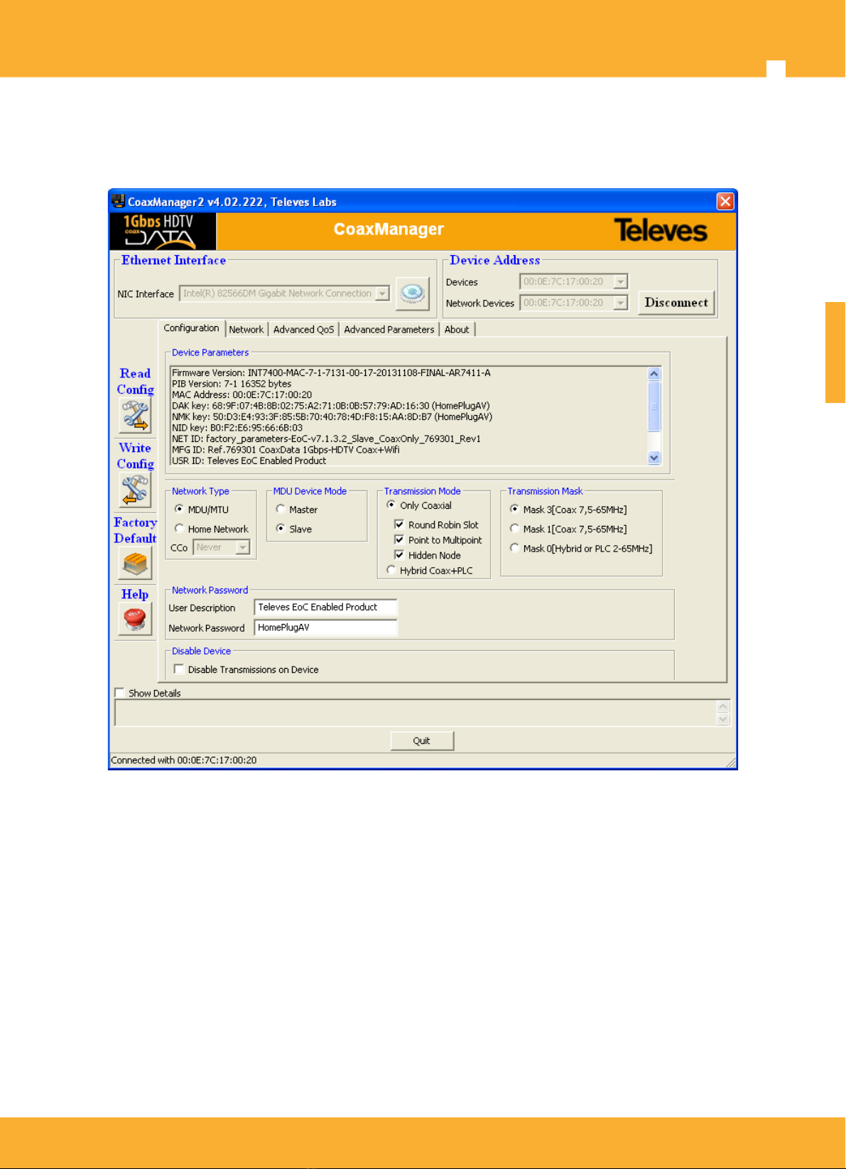
Device Configuration................................................................................................................................ 8
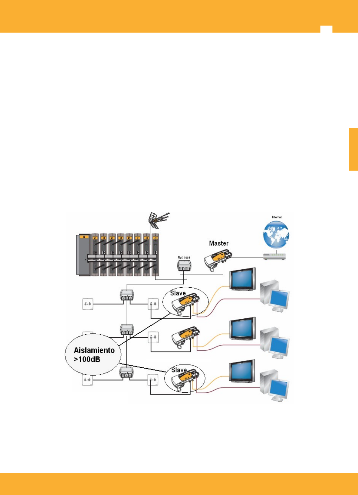
MDU Configuration...................................................................................................................................... 9
Select Transmission medium.....................................................................................................................10
Transmission Mask.................................................................................................................................... 11
Writing Device Settings .............................................................................................................................12
Checking Devices Network.................................................................................................................... 13
Device Info.................................................................................................................................................13
CCO Info....................................................................................................................................................14
Network Topology...................................................................................................................................... 15
Generating traffic to verify network links ...................................................................................................16
Generating Reports for Checking Network State...................................................................................... 16
Setting QoS parameters (Advanced User) ............................................................................................ 18
Default Priorities.........................................................................................................................................18
Priority Levels Assignment.........................................................................................................................19
TTL - Time to Live......................................................................................................................................19
Buffer Allocation, Priority Thresholds.........................................................................................................20
Bandwidth Limit..........................................................................................................................................21
Bandwidth Limit with QoS..........................................................................................................................21
Setting Advanced Configuration ........................................................................................................... 23
IGMP options............................................................................................................................................. 23
Number of Users per Slave........................................................................................................................ 25
Network Mitigation..................................................................................................................................... 28
Factory Defaults Button............................................................................................................................. 29
Advanced Power Management..................................................................................................................29
Advanced MME Features.......................................................................................................................... 30

CoaxManager™User Guide
4
Important safety instructions
General installation conditions
Before handling or connecting the equipment,please read this manual.
In order to reduce the risk of fire or electric shock, do not expose the equipment to rain or
moisture.
Do not take the cover off the equipment without disconnecting it from the AC power.
Do not obstruct the equipment’s ventilation system.
Please allow air circulation around the equipment.
The equipment must not come into contact with water or even be splashed by liquids. Do not
place containers with water on or near the equipment if it is not adequately protected.
Do not place the equipment near sources of heat or in excessively moisture conditions.
Do not place the equipment where it may be affected by strong vibrations or knocks.
How to use the equipment safely
The powering supply of this product is: 100-264 Vac~ 50/60 Hz.
If any liquid or object falls inside the equipment, please contact a specialized technician.
To disconnect the equipment from the mains, pull from the connector, and never pull from the
cable.
Do not connect the equipment to the mains until all the other connections have been made.
The AC Power socket that is going to be used to connect the equipment should be located
nearby and should be easily accessible.
Electrical safety symbols
This symbol indicates compliance with the requirements of CE mark.
This symbol indicates that the equipment is for indoor use only.
This symbol indicates that the equipment complies with the safety requirements for
class II equipment.
ENGLISH
www.televes.es

Televes
®
5
Introduction
Application Description
CoaxManager™ software allows CoaxDATA™ device configuration, setting different modes of operation,
checking installation state and links between devices. CoaxManager™ also allows configuration of QoS
parameters, and other options such as activation of low-power modes for energy efficiency,
Features
Check coax or PLC installation obtaining links status and traffic rates between devices.
Create PDF reports of network status for later analysis.
Allows basic device configuration setting MxU/HomeNetworking operating modes.
Set Network password for create several system networks. You can install up to four masters
(each with a different key) on the same coaxial network.
Allows configuration of QoS parameters supporting four priority levels based on IEEE 802.1Q
VLAN tags or IPv4 ToS (Type of Service).
Supports Advanced Features to configure IGMP, number of users or Low Power Mode.
System Requirements
Application works with Windows 2000/XP/Vista/7/8
Application works on Mac OS X and Linux Operating systems with virtualization based on Oracle
VM VirtualBox software for Windows 2000/XP/Vista/7/8.
Application requires installation of additional Winpcap library (http://www.winpcap.org/install/
default.htm). If library is not installed, CoaxManager auto atically install on your PC.
Syste is fully Plug & Play and requires no installation of any additional software or drivers.
Supported CoaxDATA Devices
Following CoaxDATA devices are supported by application:
•Ref.7689 CoaxDATA™ 200Mbps-HDTV
•Ref.768973 CoaxDATA™ 200Mbps-HDTV 1xEth
•Ref.769201 CoaxDATA™ 1Gbps-HDTV
•Ref.769202 CoaxDATA™ 1Gbps-HDTV with SFP
•Ref.769203 CoaxDATA™ 1Gbps-HDTV 1XEth
•Ref.769301 CoaxData™ 1Gbps-HDTV 3XEth + Wifi
www.televes.es

CoaxManager™User Guide
6
Installing CoaxManager Application
CoaxManager application installed through an executable that guide the user through the installation
process.
Language selection: This option selects setup language
Follow installer instructions to complete applcation installation. Read carefully license before use
program and approval before continue.
Once installed application will appear on your desktop the icon below:
ENGLISH
www.televes.es

Televes
®
7
Connecting CoaxDATA Modem to CoaxManager
After installing application, when CoaxManager start scan all computer ethernet interfaces trying to find
connected devices. In the case of identifying a device already connected, get information associated
therewith.
Application provides two combos NIC Interface and Devices showing interfaces and devices that have
been located within these interfaces. When pressed in combo Devices updates automatically Network
Devices list, showing local device (connected directly through ethernet) and all devices that it has
located within its network. .
Click on Connect/Disconnect Button to select which device you want to configure. Different operations
are available :
•Read Config: Reads connected device configuration. This operation is performed automatically
when connected to a device.
•Write Config: Write configuration on connected device. Configuration is changed through tab
GUIs.
•Factory Defaults: Sets device to factory settings. Be careful with this option since restore to
factory configuration causes lose any settings you made on it. This button has the same effect as
Factory Defaults button located on the front of the modems.
•Help: This manual.
Once connected to device we have access to different tabs that show different information about it.
If you can not connect to device, verify that this is correctly
connected via an Ethenet cable. If there is an intermediate switch or
other network devices, are configured properly.
www.televes.es

CoaxManager™User Guide
8
Device Configuration
Operation ode setting can be perfor ed through Configuration ta , where shows device info and also
those fields that configure device access ode, network password or trans ission ask.
Device Parameters displays information about device:
•Firmware Version: Version Info of Device Firmware.
•PIB Version: Device PIB Version (Parameters Information Block) . PIB stores user configuration
changes and contains firmware runtime parameters.
•MAC Address: Device MAC Address. All Televes MAC Address start with 00:0E:7C hexadecimal
values and are registered on IEEE.
•DAK key (Device Access key): Key established in the manufacturing process and determines
access to devices when it occurs remotely (via coaxial). Knowledge of this key is essential for
updating/configuring devices remotely, although default DAK key value is always the same, on
manufacturing proccess, simplifying devices configuration.
•NMK key (Network Management Key): Key set by the user and allows creation of different data
networks named AVLN. This 128bit hexadecimal key, is generated based on the Network
Password field value using a hash algorithm. NMK key determines whether a slave can connect
to a master or not and only devices with the same NMK can be connected together.
ENGLISH
www.televes.es

Televes
®
9
•NET ID, MDF ID, USR ID: Description fields determining the network name, Televes product
description and user description, done by the installer. Installer can change descriptions that
make sense in the coaxial network as the location of the modem, its role in the network or who is
using it.
•MDU mode: Indicates whether MDU mode is active or not.
•CCo mode (Central coordinator): CCo is responsible for coordinating communications between
devices. There are three options: CCo Auto: Device negociates with other who is CCo, Cco
Never: Device never is CCo, CCo Always: Device is Always CCo.
- On MDU mode: Master is always CCo, and slave never. CCo mode is not configurable.
- On Homenetworking mode: CCo Auto is default mode and CCo is assigned by negociation
between devices. When devices negociate who is CCo, all devices communicate with each other.
On hybrid networks with PLC medium or on networks where communication between all devices
are not guaranteed, installer must configure devices as well CCo never, well CCo Always, and
CCo Always device be connected to the router that gives Internet service . This avoids problems
with the negotiation of CCo Auto mode in case of lack of communication between all devices.
•Disable Device Transmissions: This options allows disable device transmissions and avoids
data transmission on network. Coaxmanager application still connect to device for management
but device cannot transmit data avoiding bandwith consumption.
MDU Configuration
Sets operating mode of the device.
Home Networking: This is default mode setting
at the factory and allows the creation of a local
area network where all devices communicate with
each other. These networks are usually created
when the modem is used to extend internet
services within a house. Default mode that is
retrieved using the Defaults button.
MDU/MTU (Multi-Dwelling/Multi-Tenant Unit). This
mode uses current coaxial network on a building
or house to communicate from the headend with
each of modems installed on coaxial outlets,
providing access to multiple dwellings without can
communicate with each other. In this mode have
two modes, master and slave.
If you select MDU option is necessary to specify which mode you want:
•Master: CoaxDATA operate in master mode and is typically installed in the headend, as
described in CoaxDATA product manual. Master controls when the slaves can access the
medium synchronizing transmissions and avoiding slave conflicts.
•Slave: modem will be installed in a coaxial outlet, as indicated in CoaxDATA product
manual.
www.televes.es
ENGLISH

CoaxManager™User Guide
10
Select Transmission medium
Sets device transmission medium
•Hybrid Coax+PLC: This option indicates that operation mode is hybrid, where devices
communicate via PLC and Coax. The medium swich on front of device must be on the left and
power LED is set to orange color.
•Only Coax: In this mode of operation only coaxial is used as communication medium. The
medium swich on front of device must be on the right and power LED is set to green color.
•Round Robin Slot(Only MxU): Every Slave have chance to transmit data and reduce probability
of whole network colliding. Enable Round Robin generally enhance the throughput.
•Point to Multipoint (Only MxU): Master have chance to transmit data and reduce probability of
whole network colliding
•Enable Hidden Node(Only MxU): This option changes medium access mechanism of the
devices. Typically medium access method is based on CSMA (carrier sense medium access)
listening and checking medium is avaliable. Devices access to medium when no one else is
transmitting. This mechanism, however, requires that all of the devices can listen all
transmissions of other devices connected to the network. Depending on the coaxial network in
which the system is implemented, there may not listen slaves of other slaves transmissions due
to a high isolation of distribution outlets (> 100dB) and CSMA access mechanism in not valid.
Enable Hidden Node option replaces medium access contention for a token-based system, where
slaves transmit only when the master gives them permission. For this mechanism to work properly, all
devices on the network must have this feature enabled.
With this feature modems access to the medium only when they have permission to do so, providing
better performance in environments where the insulation between slaves is very high. Since the devices
have to get the token for access to the medium, there is a 20% reduction in the total thoughput system.
This feature is enabled by default when user select Coaxial Medum to transmit. Disable only when
isolation between slaves is a known low value.
ENGLISH
www.televes.es

Televes
®
11
Transmission Mask
This option allows setting the transmission mask to use:
•Mask 0, Hybrid Mask: This mask transmission is set by default when it is being used in
HomeNetworking. Signal starts in very low frequency (2Mhz) to assure transmission on power
line network.
•Mask 1, Only Coaxial: This Transmission mask is used in Coaxial Only mode, the signal starts at
a higher frequency (7.5 MHz instead of 2Mhz) avoiding the possible degradation of the
communication by using very low frequencies (2 to 7.5 Mhz): noise produced by power switching
sources, ground earth on installation, etc...
This mask is used on coaxial transmission at CoaxDATA Ref.200Mbps ref.7689 and ref.768973. It
is similar to the Mask 3 and no spectral difference, only provided for compatibility between
different CoaxDATA 200Mbps and 1Gbps products and different firmware versions.
•Mask 3, Only Coaxial: Transmission mask used in Coaxial Only mode, the signal starts at a
higher frequency (7.5 MHz instead of 2Mhz) avoiding the possible degradation of the
communication by using very low frequencies (2 to 7.5 Mhz): noise produced by power switching
sources, ground earth on installation, etc...
This transmission mask is used by default on CoaxDATA1Gpbs devices like refs 769201, 769202
and 769203.
Frequencies Range used by different transmission masks depend on the product being used
Mask 0
Hybrid Mask 1
Only Coax Mask 3
Only Coax
CoaxDATA 200Mbps
Ref.7689, 768973 2-30Mhz 7,5-30Mhz 7,5-30Mhz
CoaxDATA 1Gbps
Ref.769201, 769202, 769203 2-67,5Mhz 7,5-67,5Mhz 7,5-67,5Mhz
Network Password, Create an AVLN Network
This option allows you to set the network key (NMK) devices. All devices that want to communicate
within the same network need the same key NMK. Network set up multiple devices with same key are
called AVLN (HomePlug AV Logical Networks) .
NMK is a 128-bit Hexadecimal value, in order to generate valid NMK in a easy way, Network Password
on CoaxManager provide a text passphrase, which through a hash algorithm, generate necessary NMK.
The passphrase must be entered without any spaces.
Default Network Password is “ omePlugAV” which generate NMK key
50:D3:E4:93:3 F:85:5B:70:40:78:4D:F8:15:AA:8D:B7( omePlugAV).
Network key also defines various networks established in a coaxial
network called AVLN (Associated Logical Virtual Network). It is possible
to set up four masters simultaneously in a coaxial network.
If user enters a different network key that default, HomePlugAV, next time you connect to device for
safety CoaxManager prompted the introduction of it.
Be careful and don't forget the password to connect with devices later.
www.televes.es

CoaxManager™User Guide
12
In case you have forgotten the password, you have a button on the front
of the device called Factory Defaults Button that allows the device
restored to factory settings and reset network key as the default key,
omePlugAV.
User Description
Description that user wants to assign to the device. Descriptions can be set to what makes sense for the
installation and the location of the modem, its role in the network or the user who is using it.
Writing Device Settings
Once the user has configured CoaxDATA modem with the appropriate values, Write Config Button
write configuration on device. Configuration is stored in a memory area dedicated to user settings.
If you have issues about setting up or want to delete, Press Factory Default Button to restore the device
to the factory, eliminating user settings.
When writing the configuration to a remote device connected through
the coaxial, be careful if you change the network key, Network
Password, since when change key, change network membership and
can not reconnect to device remotely.
By changing the network key loses connectivity via coaxial and
reconfigure device will have to do well locally, connecting in the place
where it is installed, or set as network key local device the same as the
remote device. The same also applies if you change the transmission
mask or MxU master/slave mode.
ENGLISH
www.televes.es

Televes
®
13
Checking Devices Network
CoaxManager can check data network created with tab named Network that allows you to view the
network information associated with a device and other devices as part of the same AVLN (Associated
Logical Virtual Network), ie, the devices they have been programmed with the same Network password.
Device Info
Parameters shown in Device Info:
•MAC: MAC address of the device that we have connected.
•TEI (Terminal equipment identifier): Is an unique identifier of a device on a network. It can
accommodate values from 1 (master) to 253 (slaves) MxU mode, and up to 64 slaves on
HomeNetworking mode.
•Hosts Info: List of different users who have connected to the device from its Ethernet interface.
•Ethernet Link: Indicates if any of the two Ethernet interfaces of the device is connected. If is On,
this field indicates that the device has someone connected via Ethernet.
•Get Counters: This button allows access to the information packets transmitted by the device.
The counters displayed are those associated with the coaxial transmission protocol not Ethernet
packet count, so these counters are not suitable to measure the traffic sent by a user, and only
used for informative purposes.
www.televes.es

CoaxManager™User Guide
14
•Ethernet Stats (Only MxU): This button get ethernet statistics of device: Transmission and
reception rates between ethernet and coaxial interfaces of device and show rate graphs
CCO Info
Parameters shown in CCo Info:
•CCo MAC: MAC address of the device with CCo functions (Central Coordinator) on the network.
On MxU, displays MACAddress of network master.
•CCo TEI (Terminal equipment identifier): Is an unique identifier of a device on a network. It is
always 1
•NID (Network identifier): When a master proceeds to create new networks on coaxial data
generated Network identifiers value by a hash algorithm. In same network can coexists up to 4
masters with same Netwok Password, creating same AVLN, but with a different NID Identifier. A
slave may choose to connect to a master NID or with other, depending on channel conditions.
•SNID (Short Network identifier): Value derived from the NID but a single byte. This value is used
by slaves to uniquely identify the master who joined to form a network.
ENGLISH
www.televes.es

Televes
®
15
Network Topology
This section contains information related to network modems. When the application is connected to the
master shows the links established with the slaves.
When device has link set but none devices connected to Ethernet ports show a MAC Bridge = FF: FF:
FF: FF: FF: FF and displays a estimate of the channel's bandwidth with three colours green, orange or
red.
When device have Ethernet hosts and really there is a flow of information between the master and a
slave, you will see information on the channel coding (Mbps) in the columns for TXCoded / Raw (Mbps)
and RXCoded / Raw (Mbps), which indicate rates maximum reached by the channel coding on each of
the links.
Attenuation conditions, channel noise or zero frequency response can alter the values obtained for
throughput. To make more intuitive analysis of the values in the application has chosen a range of colors
to indicate the status of the channel
Indicates that the link operates
at maximum rate coaxDATA 200Mbps-HDTV (120Mbps<throughput<150Mps)
coaxDATA 1Gbps-HDTV (300Mbps<throughput<450Mps)
Indicates that the link operates
at medium rate coaxDATA 200Mbps-HDTV (70Mbps<throughput<120Mps)
coaxDATA 1Gbps-HDTV (170Mbps<throughput<300Mps)
Indicates that the link operates
at poor rate coaxDATA 200Mbps-HDTV (throughput<70Mps)
coaxDATA 1Gbps-HDTV (throughput<170Mps)
CoaxManager also provide data about the link tonemap (set of carriers with QAM 4096, QAM 1024,
QAM 256,..., QPSK) and transmission mask, which indicates whether the carriers are attenuated or
transmitting.
By clicking directly on the link you will get the following window with all the data on it.
This information allows to know in addition to providing the link information about frequencies where, by
excessive noise or channel attenuations, are decreased their rate tonemap and each of the carriers
contributing to the data stream.
www.televes.es

CoaxManager™User Guide
16
•Source and Destination MAC: MAC Address of devices that MAC devices that make up the link.
•TX Rate Coded/PHY y RX Rate Coded/PHY (Mbps): Estimated Channel rate, for both
transmission and reception.
•Avg.SNR: Average SNR estimation of received signal
•Avg.Attenuation: Average attenuation of the signal in the transmission network.
Generating traffic to verify network links
Some of the information associated with the devices are shown only in the event that there is effective
transmissions between two devices. If a device is not connected to any PC, STB or other devices,
Generate Traffic button allows virtual generation of traffic between connected device and remote devices
that are part of the network.
This feature is only available when connected locally to a device through an
Ethernet cable, but is not available when CoaxManager connect to a remote
device.
Once the traffic generated between all links, the application displays a message indicating packet
generation is over. With this option we can get an estimate of channel between devices without any
active hosts on devices, this is useful to check the links at the time of installation of apartment buildings,
hotels, etc. ..
The duration of this test depends on the number of devices that form
the data network.
Generating Reports for Checking Network State
application can generate reports containing all the information concerning the status of the network.
These reports allow you to export information generated by the application in PDF for later review.
Generate Report Button automatically generate the PDF report :
ENGLISH
www.televes.es

CoaxManager™User Guide
18
Setting QoS parameters (Advanced User)
This tab allows configuration of the QoS parameters of a device.
CoaxDATA devices have various QoS mechanisms that allow prioritize traffic by type: either video, voice
or data. Each one of these traffic can have, depending on the installation requirements and provide
different mechanisms for ensuring priority.
You can set up to 4 priority levels, called CAP "Channel Access Priority": CAP3 (highest priority), CAP2,
CAP1 and CAP0 (lowest priority). Packets belonging to higher priority are transmitted first.
There are three mechanisms for priority setting. Are shown in order of
preference in the firmware.
- Default Priorities
- Mapping as 802.1p and / or cough
- QoS Rules (CoaxManagerPro Only)
Default Priorities
This section allows the assignment of priority levels based on packets by type. This assignment
overrides VLAN tag (802.1p) or IPv4 ToS (Type of Service) priority settings:
Unicast (default CAP1): sets the default priority for unicast packets without VLAN tag transmitted
between devices
IGMP (default CAP3): Permite asignar la prioridad de paquetes IGMP utilizados para gestionar
streams multicast.
ENGLISH
www.televes.es

Televes
®
19
Multicast (default CAP1): Prioridad asignada a streams multicast que no son gestionados por
IGMP; es decir, aquellos streams multicast para los cuales no se han generados IGMP reports ni
existen IGMP queries que los gestionen.
Multicast gestionados por IGMP (default CAP3): Prioridad asignada a streams multicast que
han sido gestionados por los dispositivos mediante IGMP Snooping.
Priority Levels Assignment
Packets can be assigned to the desired priority level based on:
•VLAN 802.1P Priority: VLAN tags are small data field in 802.1 Ethernet packets and determines
or specifies the packet type in question. This tag is normally assigned at source or swiches
established by the network depending on the input port (or any other parameter: multicast, UDP.
Destination port, etc). You can set the "User Priority" Tag VLAN 802.1P priority levels CAP0-
CAP3.
•IP Traffic Class: Priority based on ToS (Type of Service) of IP packets. RFC 1349 describes this
field and values like delay, rate optimization or reliability. You can assign one of four priority levels
CAP0-3 device according to the first 3 bits of the ToS field (ToS Precedence).
TTL - Time to Live
CoaxDATA devices allow you to specify a parameter called TTL (Time to Live) for each priority level,
CAP. This parameter indicates how long a packet can stay in the buffers (SDRAM) before exceeding the
maximum lifetime. Once established time is out packet is dropped.
The time a packet remains in the device buffers before transmission depends on network traffic
conditions, the number of modems that make up the network and its effective occupation, so that the
establishment of these values should be account the implementation and the estimated rate of service.
By example, this mechanism is often used in VoIP or Video packets where packet time on buffer is
excessive and can be discarded because elapsed time is too late at the receiver and is not necessary for
decoding.
TTL values for each priority queue and MME (Management Messages, which are used by the application
www.televes.es

CoaxManager™User Guide
20
management like CoaxManager) can be set. The default values are set as follows:
•CAP0 traffic: 2000 msec (used for TCP data traffic)
•CAP1 traffic: 2000 msec (used for TCP data traffic)
•CAP2 traffic: 300 msec (used for UDP video/music traffic)
•CAP3 traffic: 300 msec (used for VoIP traffic)
•MME traffic: 300 msec (used for Management Messages)
It is recommended not to change TTL values unless you know exactly what you
are doing.
Buffer Allocation, Priority Thresholds
This option determines memory size (buffers) for each of the priorities. When buffers are full, packets are
dropped based on their priority.
Thresholds determining buffers available for each
priority.
Available buffers are managed in terms of a percentage
allocated to each CAP. When the percentage of
allocated buffers exceeded, lower priority packets are
discarded but higher priority is still admitted.
By enabling this option, the packages are stored waiting to be transmitted, but if at any time it exceeds a
certain percentage of occupancy, the packet is discarded leaving room for higher priority packets.
example:
Suppose you have the following prioritization:
Assigned Percentage Total Percentage
(accumulative)
CAP 0 and higher = 20% 20 %
CAP 1 and higher = 25% 45 %
CAP 2 and higher = 45% 90 %
CAP 3 = 10% 100 %
At any given time:
- If the total number of buffers used for transmission is less than 20% shall be
allowed traffic of all priorities (CAP 0 or better).
- If the total number of buffers used exceeds 45% shall be allowed only packages
or higher priority CAP1 (CAP1, CAP2 or CAP 3).
- If the number of occupied buffers is greater than 90% are permitted only packets
with higher priority than CAP 2, ..., and so on.
ENGLISH
www.televes.es
Table of contents
Other Televes Modem manuals