TeleVideo 955 User manual
TeleVideo~
--Qispley
--Te-rmineJ--
Operator's
Manual
Televideo
S~:rstems,
Inc.
---._"

TELEVIDEO®
955
VIDEO DISPLAY TERMINAL
OPERATOR I S
MANUAL
TeleVideo
Document
131969-00-B
11
September
1985
Copyright
Copyright
(c)
1985
by
TeleVideo
Systems,
Inc.
All
rights
reserved.
No
part
of
this
publication
may
be
reproduced,
transmitted,
transcribed,
stored
in
a
retrieval
system,
or
translated
into
any
language
or
computer
language,
in
any
form
or
by
any
means,
electronic,
mechanical,
magnetic,
optical,
chemical,
manual,
or
otherwise,
without
the
prior
written
permission
of
TeleVideo
Systems,
Inc.,
1170
Morse
Avenue
P.O. Box
3568
Sunnyvale,
CA
94088-3568
800/521-4897
Disclaimer
TeleVideo
Systems,
Inc.
makes
no
representations
or
warranties
with
respect
to
this
manual.
Further,
TeleVideo
Systems,
Inc.
reserves
the
right
to
make
changes
in
the
specifications
of
the
product
described
within
this
manual
at
any
time
without
notice
and
without
obligation
of
TeleVideo
Systems,
Inc.
to
notify
any
person
of
such
revision
or
changes.
FCC
Class
A
Warning
This
peripheral
equipment
generates,
uses,
and
can
radiate
radio
frequency
energy.
If
not
installed
and
used
in
accordance
with
the
instruction
manual,
it
may
cause
interference
with
radio
emissions.
This
peripheral
equipment
has
been
tested
and
found
to
comply
with
the
limits
for
a
Class
A
computing
device,
pursuant
to
Subpart
J
of
Part
15
of
FCC
Rules,
which
are
designed
to
provide
reasonable
protection
against
radio
frequency
interference
when
operated
in
a
commercial
environment.
Operation
of
this
equipment
in
a
residential
area
is
likely
to
cause
interference,
in
which
case
the
user
at
his
own
risk
and
expense
wi
11
be
required
to
correct
the
interference.
The
use
of
nonshielded
I/O
cables
may
not
guarantee
compliance
with
FCC
RFI
limits.
TeleVideo
is
a
registered
trademark
of
TeleVideo
Systems,
Inc.
Televideo
Systems,
Inc.,
1170
Morse
Avenue
P.O. Box
3568
Sunnyvale,
CA
94088-3568
800/521-4897
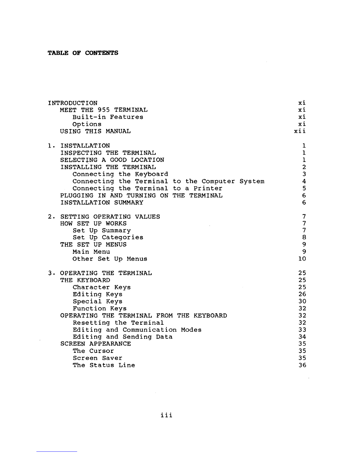
TABLE OF CONTENTS
INTRODUCTION
MEET
THE
955
TERMINAL
Built-in
Features
Options
USING
THIS
MANUAL
1.
INSTALLATION
INSPECTING
THE
TERMINAL
SELECT+NG A
GOOD
LOCATION
INSTALLiNG
THE
TERMINAL
Connecting
the
Keyboard
Connecting
the
Terminal
to
the
Computer
System
Connecting
the
Terminal
to
a
Printer
PLUGGING
IN
AND
TURNING
ON
THE
TERMINAL
INSTALLATION
SUMMARY
2.
SETTING OPERATING VALUES
HOW
SET
UP
WORKS
Set
Up
Summary
Set
Up
Categories
THE
SET
UP
MENUS
Main
Menu
Other
Set
Up
Menus
3.
OPERATING
THE
TERMINAL
THE
KEYBOARD
Character
Keys
Editing
Keys
Special
Keys
Function
Keys
OPERATING
THE
TERMINAL
FROM
THE
KEYBOARD
Resetting
the
Terminal
Editing
and
Communication
Modes
Editing
and
Sending
Data
SCREEN APPEARANCE
The
Cursor
Screen
Saver
The
Status
Line
iii
xi
xi
xi
xi
xii
1
1
1
2
3
4
5
6
6
7
7
7
8
9
9
10
25
25
25
26
30
32
32
32
33
34
35
35
35
36

4.
MAINTENANCE
AND
ASSISTANCE
TROUBLESHOOTING
Troubleshooting
Table
Running
the
Self
Test
Checking
the
Line
Fuse
IF
YOU
NEED
ASSISTANCE
Technical
Support
Customer
Service
Service
Under
Warranty
Shipping
the
Terminal
5.
PROGRAMMING
THE
955
ENTERING
COMMANDS
Command
Descriptions
Using
Commands
in
Your
Programs
Entering
Commands
From
the
Keyboard
VERIFYING
OPERATIONS
Self
Test
Monitor
Mode
CHANGING OPERATING VALUES
Terminal
Operating
Modes
Variable
Operating
Values
Saving
Operating
Values
Programming
Compatibility
Mode
Changing
the
Screen
Refresh
Rate
Resetting
the
Terminal
RUNNING A
PROGRAM
6.
CONTROLLING
THE
TERMINAL'S OPERATION
KEYBOARD
AND
BELL
Keyboard
Repeat
Mode
Locking/Unlocking
the
Keyboard
Locking
Four
Terminal
Keys
Editing
Key
Mode
Keyclick
Sounding
the
Bell
Selecting
the
Bell
Column
Margin
Bell
Mode
SCREEN APPEARANCE
Screen
Saver
Screen
Visibility
Screen
Background
Visual
Attributes
Attribute
Space
Mode
Normal
Intensity
Mode
Attribute
Base
Mode
Selecting
the
Status
Line
Attribute
Cursor
Style
Columns
per
Line
Mode
iv
Contents
39
39
39
41
42
43
44
44
44
44
45
45
46
46
47
47
47
48
49
49
50
50
51
52
52
54
55
55
55
55
56
56
56
56
57
57
57
57
58
58
58
60
60
60
61
61
61

CHARACTER
SETS
AND
BLOCK
GRAPHICS
Selecting
a
Character
Set
Special
Graphics
Mode
Multinational
Character
Set
Data
Word
Mode
Block
Graphics
Optional
Graphics
Firmware
7.
EDITING
EDITING
MODES
Autowrap
Mode
New
Line
Mode
DOWN
Key
Mode
Write
Protect
and
Protect
Modes
ADDITIONAL
SCREEN
MEMORY
Selecting
the
Number
of
Lines
per
Page
Autopage
Mode
Moving
to
Another
Page
SCROLLING
Controlling
the
Rate
of
Scrolling
Defining
a
Scrolling
Region
Line
Lock
CURSOR
CONTROL
Line
Feed
and
Reverse
Line
Feed
Directional
Cursor
Movement
Addressing
the
Cursor
Reading
the
Cursor
Addressing
the
Cursor
in
Decimal
Units
Cursor
Home
Reading
the
Cursor
in
Decimal
Units
TAB
STOPS
Setting
a
Column
of
Tab
Stops
Moving
the
Cursor
to
a
Tab
Stop
Clearing
Typewriter
Tab
Stop(s)
Clearing
Field
Tab
Stop(s)
EDITING
DATA
Line
and
Page
Edit
Insert
and
Replace
Mode
The
Replacement
Character
Inserting
Data
Deleting
Data
Erasing
Data
Clearing
Data
v
Contents
62
62
62
63
64
64
65
67
67
67
67
68
68
71
72
73
74
75
75
76
76
78
78
80
83
84
85
85
85
.86
86
87
88
88
89
89
89
90
90
91
93
94

Contents
8.
COMMUNICATIONS
97
CHANGING
PORT
OPERATING
VALUES
97
SETTING
UP
COMMUNICATIONS
WITH
THE
COMPUTER
98
Selecting
a
Handshaking
Protocol
98
Receive
Buffer
Fill
Limit
99
Transmission
Control
Mode
99
Selecting
the
Transmit
Delay
Rate
100
Communication
Modes
100
Setting
the
Communication
Mode
102
SENDING SCREEN
DATA
102
Delimiters
102
Reprogramming
Delimiters
103
Data
Markers
103
Sending
Text
104
LOADING
AND
SENDING MESSAGES
107
Sending
the
Terminal's
Identification
108
The
Answerback
Message
108
Displaying
the
Bottom
Information
Line's
Contents
108
Selecting
Both
Information
Lines'
Contents
109
Loading
the
User
Messages
109
Sending
the
Information
Line
Contents
111
THE
FUNCT
KEY
111
PRINTING
112
Print
Commands
112
Page
Print
Flip
Mode
116
Printer
Handshaking
Protocols
116
Page
Print
Terminator
118
9.
REPROGRAMMABLE
KEYS
119
FUNCTION
KEYS
119
Selecting
the
Function
Key
Set
121
Reprogramming
Function
Keys
121
Saving
the
Contents
of
the
Function
Keys
124
Invoking
a
Function
Key
124
REPROGRAMMING
EDITING
KEYS
125
The
SEND
Key
125
One
Editing
Key
125
All
Editing
Keys
128
vi

APPENDICES
A
SPECIFICATIONS
B STATEMENT OF LIMITED
WARRANTY
C
ASCII
CODE
TABLES
D MONITOR
MODE
CONTROL
CHARACTERS
E
CURSOR
COORDINATES
F FOREIGN CHARACTER SETS
G MULTINATIONAL CHARACTER
SET
H
CONTROL
CODES
AND
ESCAPE SEQUENCES
I CALCULATOR
MODE
GLOSSARY
INDEX
QUICK REFERENCE GUIDE
vii
Contents
A-I
A-4
A-S
A-7
A-8
A-9
A-14
A-16
A-23
G-l
X-I
Q-l

Contents
LIST
OF
FIGURES
1-1
1-2
1-3
1-4
1-5
2-1
2-2
2-3
2-4
2-5
2-6
3-1
3-2
3-3
3-4
3-5
3-6
4-1
4-2
4-3
5-1
6-1
6-2
7-1
7-2
7-3
7-4
7-5
7-6
7-7
7-8
7-9
7-10
8-1
8-2
F-l
F-2
F-3
F-4
F-5
F-6
F-7
F-8
Comfortable
Terminal
Lighting
Ideal
Terminal
Placement
955
Terminal,
Front
View
955
Terminal,
Rear
View
Pin
Numbers
(25-Pin
RS-232
Connector)
Main
Menu
Main
Port
Menus
Print
Communications
Menu
Screen
Menus
Keyboard
Menus
Programming
Menus
Character
Keys
Editing
Keys
Special
Keys
Data
Sent
by
the
Unshifted
SEND
Key
Data
Sent
by
the
Shifted
SEND
Key
955
Status
Line
Location
of
the
Line
Fuse
Good
Fuse
Burned-Out
Fuse
Typical
Monitor
Mode
Display
Special
Graphics
and
Multinational
Characters
Display
with
Three
Blocks
of
Graphics
Effect
of
Line
Feed
and
Carriage
Return
Commands
Sample
Protected
Form
with
Spaces
Left
for
Data
Entry
Partial
Page
of
Memory
Displayed
on
the
Screen
Dividing
Memory
into
Pages
Cursor
Movement
in
Autopage
Mode
Cursor
Movement
Between
Adjacent
Pages
Scrolling
Movement
Within
a
Scrolling
Region
Setting
Field
Tab
Stops
Deleting
Data
Erasing
Data
Data
Flow
in
Communication
Modes
Print
Modes
U.S.
ASCII
Keyboard
Layout
U.K.
Keyboard
Layout
French
Keyboard
Layout
German
Keyboard
Layout
Spanish
Keyboard
Layout
Finnish
Keyboard
Layout
Norwegian
Keyboard
Layout
Italian
Keyboard
Layout
viii
2
2
3
3
4
9
10
14
16
19
22
26
26
31
34
34
36
43
43
43
48
63
65
68
70
72
73
74
74
77
87
92
93
101
113
A-9
A-I0
A-I0
A-II
A-II
A-12
A-12
A-13
Contents
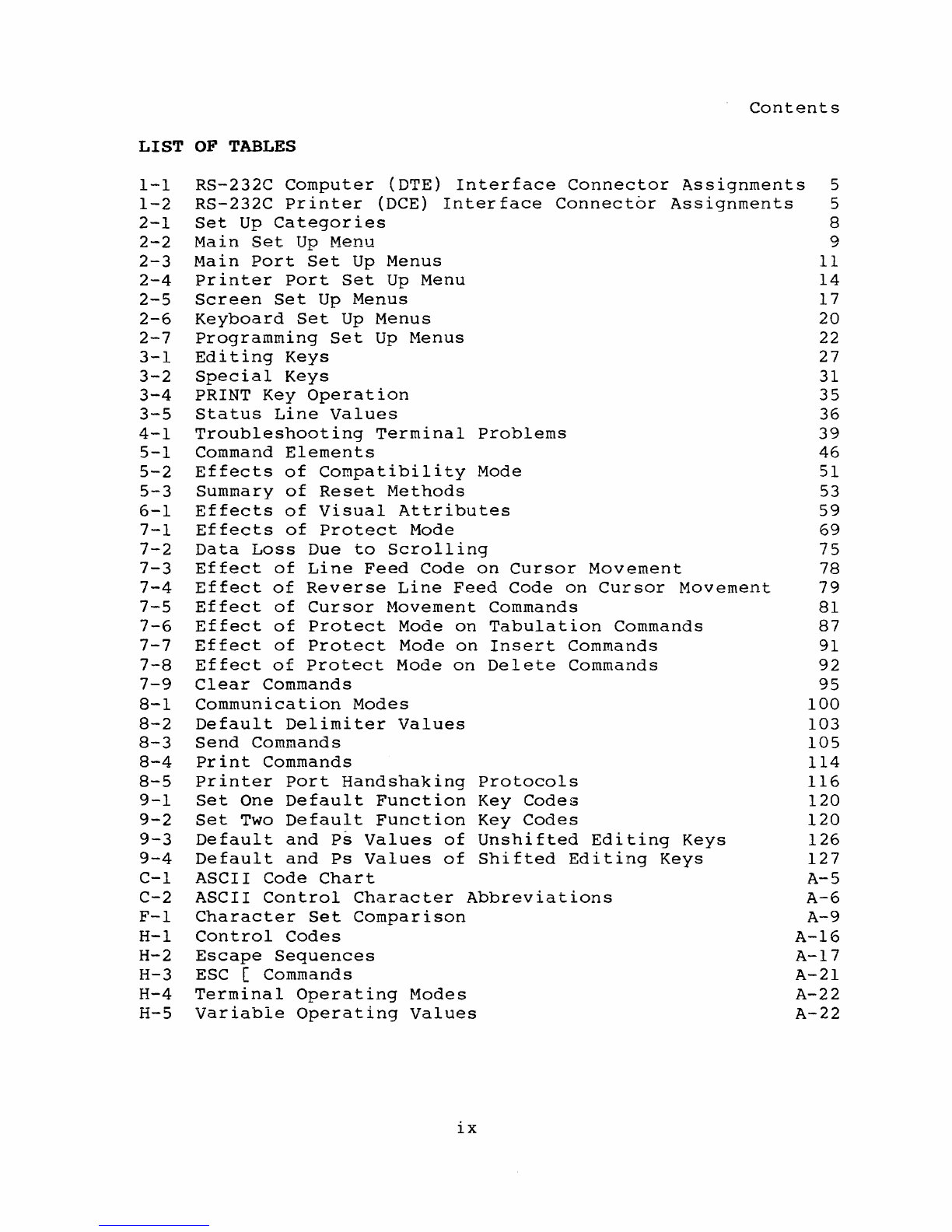
LIST
OF
TABLES
1-1
RS-232C
Computer
(DTE)
Interface
Connector
Assignments
5
1-2
RS-232C
Printer
(DCE)
Interface
Connector
Assignments
5
2-1
Set
Up
Categories
8
2-2
Main
Set
Up
Menu 9
2-3
Main
Port
Set
Up
Menus
11
2-4
Printer
Port
Set
Up
Menu
14
2-5
Screen
Set
Up
Menus
17
2-6
Keyboard
Set
Up
Menus
20
2-7
Programming
Set
Up
Menus
22
3-1
Editing
Keys
27
3-2
Special
Keys
31
3-4
PRINT
Key
Operation
35
3-5
Status
Line
Values
36
4-1
Troubleshooting
Terminal
Problems
39
5-1
Command
Elements
46
5-2
Effects
of
Compatibility
Mode 51
5-3
Summary
of
Reset
Methods
53
6-1
Effects
of
Visual
Attributes
59
7-1
Effects
of
Protect
Mode
69
7-2
Data
Loss
Due
to
Scrolling
75
7-3
Effect
of
Line
Feed
Code
on
Cursor
Movement
78
7-4
Effect
of
Reverse
Line
Feed
Code
on
Cursor
Movement
79
7-5
Effect
of
Cursor
Movement
Commands
81
7-6
Effect
of
Protect
Mode
on
Tabulation
Commands
87
7-7
Effect
of
Protect
Mode
on
Insert
Commands 91
7-8
Effect
of
Protect
Mode
on
Delete
Commands
92
7-9
Clear
Commands
95
8-1
Communication
Modes
100
8-2
Default
Delimiter
Values
103
8-3
Send
Commands
105
8-4
Print
Commands
114
8-5
Printer
Port
Handshaking
Protocols
116
9-1
Set
One
Default
Function
Key
Codes
120
9-2
Set
Two
Default
Function
Key
Codes
120
9-3
Default
and
Ps
Values
of
Unshifted
Editing
Keys
126
9-4
Default
and
Ps
Values
of
Shifted
Editing
Keys
127
C-l
ASCII
Code
Chart
A-5
C-2
ASCII
Control
Character
Abbreviations
A-6
F-l
Character
Set
Comparison
A-9
H-l
Control
Codes
A-16
H-2
Escape
Sequences
A-17
H-3
ESC
[ Commands
A-21
H-4
Terminal
Operating
Modes
A-22
H-5
Variable
Operating
Values
A-22
ix

INTRODUCTION
MEET
THE
955
TERMINAL
Televideo's
955
terminal
is
designed
with
quality,
dependability,
and
user
convenience
in
mind.
It
is
fully
code
compatible
with
TeleVideo's
925/950
family
of
terminals,
but
also
offers
such
innovative
features
as
a
high-resolution
screen
with
amber
color
option,
64
function
keys,
and
two
operator
information
lines.
Built-in
Features
TeleVideo's
955
terminal
is
a
"smart"
terminal
with
many
built-in
features:
Full
925/950
programming
compatibility
Tilt-and-swivel
case
High-resolution
screen
l4-inch,
80/l32-column
display
Easy-to-use
set
up
menus
Switchable
space/no-space
visual
attributes
Top
and
bottom
operator
information
lines
Two
sets
of
32
programmable
function
keys
Reprogrammable
editing
keys
Special
graphics
and
multinational
character
sets
Options
The
following
options
are
available:
RS-422
communication
interface
One
or
three
additional
pages
of
memory
Tektronix
40l0/40l4-compatible
graphics
Eight
foreign-language
character
sets
No-cost
amber
screen
20
rnA
current
loop
Function
key
overlays
Blank
keycaps
WordStar(tm)-CP/M(r)
EPROM
and
keyboard
overlay
Contact
your
distributor
or
TeleVideo's
spare
parts
department
to
order
any
options.
xi

Introduction
USING THIS
MANUAL
The
first
chapters
of
the
manual
contain
general
user
information.
Chapters
I
through
3
describe
how
to
install
the
terminal,
change
operating
values
in
the
set
up
menus,
and
control
the
terminal
from
the
keyboard.
Chapter
4
lists
troubleshooting
procedures
and
tells
you
how
to
obtain
service.
Chapters
5
through
9
are
for
programmers.
They
explain
how
the
terminal
operates
and
all
the
programming
commands.
At
the
back
of
the
manual
is
reference
material:
appendices,
glossary,
index,
and
a
programmer's
quick
reference
guide.
xii

l.
INSTALLATION
This
chapter
tells
you
how
to
install
the
terminal.
The
end
of
the
chapter
summarizes
the
installation
steps.
INSPECTING
THE
TERMINAL
WARNING!
Do
not
open
the
terminal
case.
Opening
the
case
exposes
you
to
potential
shock
hazards.
If
you
wish
to
inspect
the
interior
of
your
terminal,
have
a
qualified
technician
open
the
case
and
discharge
the
voltage
for
you.
After
you
unpack
the
terminal,
keep
the
shipping
carton
and
packing
material
in
case
you
move
or
ship
the
terminal
again.
In
the
packing
carton
you
should
find
(in
addition
to
this
manual)
:
The
terminal
A
keyboard
A
coiled
keyboard
cable
A
power
cable.
Inspect
the
keyboard,
cabinet,
and
video
screen
for
shipping
damage.
If
anything
is
missinq
or
damaged,
contact
your
distributor
or
dealer.
SELECTING A
GOOD
LOCATION
Make
sure
the
site
you
have
chosen
for
the
terminal
has
4
inches
(10.2
cm)
of
clearance
for
ventilation
on
all
sides.
The
orientation
of
the
terminal's
screen
can
greatly
affect
your
comfort.
Reflections
and
bright
light
are
the
most
common
causes
of
eye
strain.
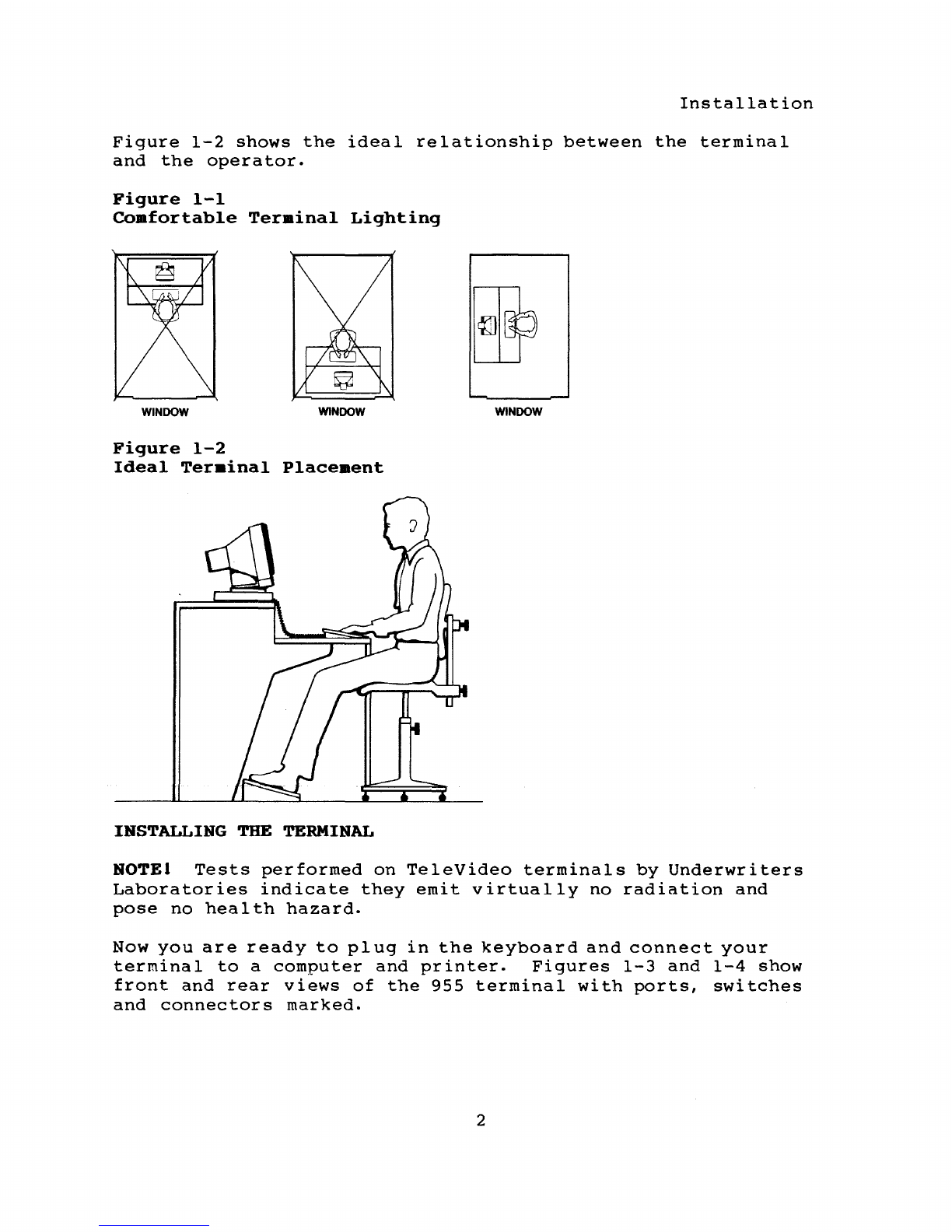
Choose
a
site
with
indirect
lighting,
away
from
windows
and
other
sources
of
bright
light,
as
Figure
1-1
shows.
You
can
avoid
fatigue
by
selecting
furniture
whose
design
is
conducive
to
good
working
posture
and
placing
the
terminal
at
the
correct
height.
The
keyboard
should
be
lower
than
the
terminal
screen.
1
Installation
Figure
1-2
shows
the
ideal
relationship
between
the
terminal
and
the
operator.
Figure
1-1
Coafortable
Teraina1
Lighting
WINDOW
WINDOW
WINDOW
Figure
1-2
Ideal
Teraina1
P1aceaent
INSTALLING
THE
TERMINAL
NOTEI
Tests
performed
on
TeleVideo
terminals
by
Underwriters
Laboratories
indicate
they
emit
virtually
no
radiation
and
pose
no
health
hazard.
Now
you
are
ready
to
pi
ug
in
the
keyboard
and
connect
your
terminal
to
a
computer
and
printer.
Figures
1-3
and
1-4
show
front
and
rear
views
of
the
955
terminal
with
ports,
switches
and
connectors
marked.
2

Installation
connecting
the
Keyboard
Plug
the
ends
of
the
coiled
keyboard
cable
into
the
front
of
the
keyboard
case
and
the
front
of
the
terminal
(Figure
1-3).
Figure
1-3
955
Ter.inal,
Front
View
Figure
1-4
955
Terminal,
Rear
View
POWERCABLE~~~~~~=
SOCKET
......
;;;;;;;;;;;;;;;;;;.~
3

Installation
connecting
the
Terminal
to
the
Computer
System
Before
you
connect
the
terminal,
make
sure
its
voltage
is
the
same
as
your
electrical
outlet's.
Your
terminal
should
carry
a
label
stating
whether
its
setting
is
115
volt
or
230
volt
ac
power.
If
you
want
to
change
the
voltage
setting,
call
the
TeleVideo
Customer
Service
Department
for
instructions.
Before
you
connect
the
terminal
to
the
computer,
measure
the
distance
between
them.
If
the
distance
is
less
than
50
feet,
you
can
use
an
RS-232C
interface
(with
a
25-pin
connector)
between
the
terminal
and
the
computer.
For
distances
more
than
50
feet,
consult
your
dealer
or
call
TeleVideo's
Peripherals
Technical
Support
Department
for
help
in
selecting
the
correct
interface.
See
the
section
on
assistance
in
Chapter
4
for
information
about
calling
TeleVideo.
If
you
use
the
RS-232C
interface,
follow
these
steps:
1.
Compare
the
suggested
pin
connector
assignments,
listed
in
Table
1-1,
with
those
required
by
your
computer.
Figure
1-5
shows
the
terminal's
pin
connector
numbers.
If
necessary,
change
the
interface
cable's
pin
assignments
(or
ask
your
service
technician
to
do
it
for
you)
.
2.
Connect
the
interface
cable
to
the
terminal's
main
port
and
the
computer's
RS-232C
port.
NOTEI
Not
all
computers
have
a
one-to-one
pin
compatibility
with
standard
RS-232C
pin
assignments.
Typically,
pins
2,
3,
and
7
are
required
to
transmit
d~ta
between
the
terminal
and
the
computer.
If
your
computer
fails
to
operate
properly,
call
the
computer
manufacturer
for
assistance
in
wiring
the
interface
cable.
Figure
1-5
Pin
Numbers
(25-Pin
RS-232
Connector)
13
\@@@@@@@@@@@
@
(~
l
@@@@@@@'~@CiJ~_~~
25
14
4
Installation
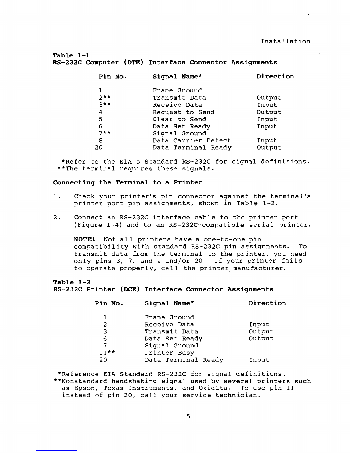
Table
1-1
RS-232C
Computer
(OTE)
Interface
Connector
Assignments
Pin
No.
Signal
Name*
Direction
1
Frame
Ground
2**
Transmit
Data
Output
3**
Receive
Data
Input
4
Request
to
Send
Output
5
Clear
to
Send
Input
6
Data
Set
Ready
Input
7**
Signal
Ground
8
Data
Carrier
Detect
Input
20
Data
Terminal
Ready
Output
*Refer
to
the
EIA's
Standard
RS-232C
for
signal
definitions.
**The
terminal
requires
these
signals.
Connecting
the
Terminal
to
a
Printer
1.
Check
your
printer's
pin
connector
against
the
terminal's
printer
port
pin
assignments,
shown
in
Table
1-2.
2.
Connect
an
RS-232C
interface
cable
to
the
printer
port
(Figure
1-4)
and
to
an
RS-232C-compatible
serial
printer.
NOTE!
Not
all
printers
have
a
one-to-one
pin
compatibility
with
standard
RS-232C
pin
assignments.
To
transmit
data
from
the
terminal
to
the
printer,
you
need
only
pins
3,
7,
and
2
and/or
20.
If
your
printer
fails
to
operate
properly,
call
the
printer
manufacturer.
Table
1-2
RS-232C
Printer
(DCE)
Interface
Connector
Assignments
Pin
No.
Signal
Name*
Direction
1
Frame
Ground
2
Receive
Data
Input
3
Transmit
Data
Output
6
Data
~et
Ready
Output
7
Signal
Ground
11**
Printer
Busy
20
Data
Terminal
Ready
Input
*Reference
EIA
Standard
RS-232C
for
signal
definitions.
**Nonstandard
handshaking
signal
used
by
several
printers
such
as
Epson,
Texas
Instruments,
and
Okidata.
To
use
pin
11
instead
of
pin
20,
call
your
service
technician.
5

Installation
PLUGGING
IN
AND
TURNING
ON
THE TERMINAL
Now
you
are
ready
to
plug
in
the
terminal
and
turn
it
on.
1.
Plug
the
power
cable
into
the
termini'll
and
into
a
grounded
wall
outlet.
See
Figure
1-4
for
the
location
of
the
power
cable
outlet
at
the
rear
of
the
terminal.
In
the
United
States,
use
a
3-prong
electrical
outlet
with
a
National
Electrical
Manufacturers
Association
(NEMA)
Standard
5-15R
rating.
If
you
use
a
two-prong
adapter,
ground
it
with
a
pigtail.
2.
Push
the
white
dot
on
the
ON/OFF
switch
on
the
right
side
of
the
grooved
panel
below
the
screen
(Figure
I-i).
3.
Listen
for
the
terminal's
bell,
after
about
a
second,
and
look
for
the
cursor
in
the
top
left
corner
of
the
screen
after
10
to
15
seconds.
If
the
screen
remains
dark,
go
to
step
5.
4.
Adjust
the
angle
of
the
terminal
by
pushing
on
the
case
until
you
can
see
the
screen
easily.
5.
Adjust
the
screen
contrast
with
the
roller
on
the
left
side
of
the
grooved
panel
below
the
screen
(Figure
1-3).
INSTALLATION
SUMMARY
1.
Unpack
and
inspect
the
terminal.
2.
Plug
the
keyboard
cable
into
the
termini'll
and
keyboard.
3.
Check
that
the
unit
has
the
correct
voltage
(115
or
230).
4.
Connect
the
appropriate
interface
cable
between
the
computer
system
and
the
terminal.
5.
Attach
a
printer
interface
cable
(if
you
are
connecting
a
printer
to
the
terminal).
6.
Plug
the
power
cord
into
the
terminal
and
wall
outlet.
7.
Turn
on
the
terminal,
listen
for
the
beep,
watch
for
the
cursor,
and
adjust
the
tilt
and
screen
contrast.
Before
using
the
terminal,
check
its
operating
values,
as
described
in
the
following
chapter.
6

2.
SETTING OPERATING
VALUES
When
you
turn
on
the
905,
it
is
ready
to
operate.
Its
factory
default
operating
values
are
set
when
it
is
manufactured.
This
chapter
tells
how
to
reset
the
default
values.
NOTEI You
can
change
all
set
up
values
with
programming
comands.
See
Chapter
5.
HOW
SET
UP
WORKS
To
change
the
955's
operating
values,
select
new
values
from
the
set
up
menus.
Each
has
an
instruction
line
at
the
top
of
the
screen
and
a
selection
line
at
the
bottom
to
guide
you.
Set
Up
Summary
1.
Press
SET
UP
(shifted
NO
SCROLL).
The
main
menu
appears.
You
can
enter
set
up
any
time,
but
if
the
computer
is
sending
data,
the
screen
stops
receiving
incoming
data
until
you
leave
set
up.
NOTE
I
If
the
SET
UP
key
has
been
disabled
by
a
programming
command
(see
Chapter
6),
you
cannot
enter
set
up.
The
terminal's
bell
sounds
and
the
main
menu
does
not
appear.
2.
Press
the
UP
and
DOWN
keys
to
display
different
set
up
menus.
3.
Press
the
LEFT
and
RIGHT
keys
to
move
from
field
to
field
in
each
menu.
4.
Press
the
space
bar
to
flip
through
the
values
in
each
field.
When
the
desired
value
appears,
simply
move
to
the
next
field
or
menu
(or
leave
set
up).
NOTE I
The
main
menu
has
action
fields.
Pressing
the
space
bar
triggers
the
action.
7
Setting
Operating
Values
5 .
Wh
e n
you
fin
ish
s e 1 e c
tin
g
set
up
val
u e
s,
pre
s
sSE
T UP
to
return
to
normal
operation.
The
message
SAVE?
yiN
appears
on
the
screen.
6.
Press
Y
to
save
your
new
values
in
nonvolatile
memory.
If
you
press
any
other
key,
the
values
you
selected
are
lost
when
you
turn
the
power
off
or
reset
the
terminal.
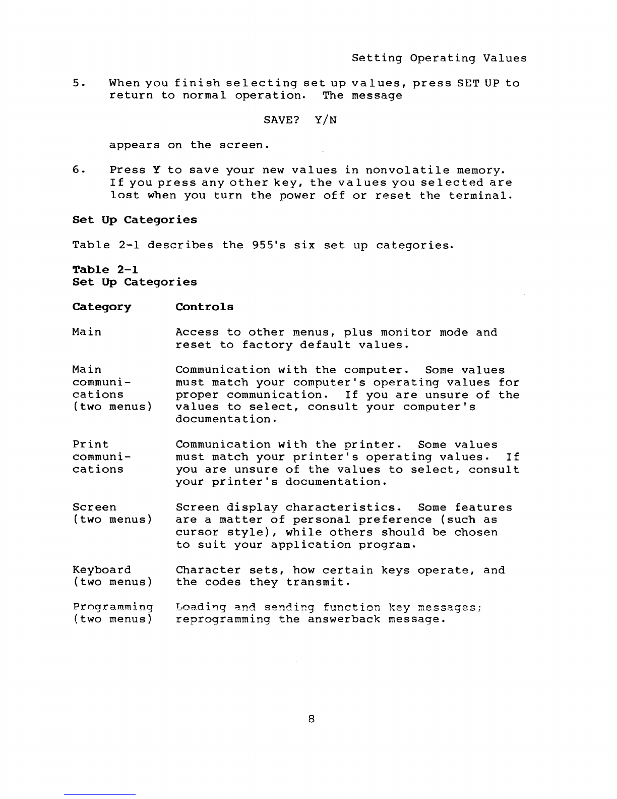
Set
Up
Categories
Table
2-1
describes
the
955's
six
set
up
categories.
Table
2-1
Set
Up
Categories
Category
Main
Main
communi-
cations
(two
menus)
Print
communi-
cations
Screen
(two
menus)
Keyboard
(two
menus)
Programming
(two
menus)
Controls
Access
to
other
menus,
plus
monitor
mode
and
reset
to
factory
default
values.
Communication
with
the
computer.
Some
values
must
match
your
computer's
operating
values
for
proper
communication.
If
you
are
unsure
of
the
values
to
select,
consult
your
computer's
documentation.
Communication
with
the
printer.
Some
values
must
match
your
printer's
operating
values.
If
you
are
unsure
of
the
values
to
select,
consult
your
printer's
documentation.
Screen
display
characteristics.
Some
features
are
a
matter
of
personal
preference
(such
as
cursor
style),
while
others
should
be
chosen
to
suit
your
application
program.
Character
sets,
how
certain
keys
operate,
and
the
codes
they
transmit.
Loading
and
sending
function
key
messages;
reprogramming
the
answerback
message.
8
Other manuals for 955
2
Table of contents
Other TeleVideo Desktop manuals

TeleVideo
TeleVideo 950 User manual

TeleVideo
TeleVideo TS 806/20 User manual

TeleVideo
TeleVideo 9320 User manual

TeleVideo
TeleVideo TS 806H User manual

TeleVideo
TeleVideo TVI-9128 User manual

TeleVideo
TeleVideo TS-1605 User manual

TeleVideo
TeleVideo 925 User manual

TeleVideo
TeleVideo TPC I SYSTEM User manual

TeleVideo
TeleVideo TS 802H User manual
Popular Desktop manuals by other brands


Dell
Dell OptiPlex 380 Setup and features information

Asus
Asus Pundit P3-PE5 Quick installation guide

Muller Elektronik
Muller Elektronik SPRAYDOS Installation and operating instructions

Asus
Asus EeeBox EB1501P user manual

Sony
Sony PCV-R526DS - Vaio Digital Studio Desktop... user guide

Compaq
Compaq BL10e - HP ProLiant - 512 MB RAM Configuration