TeleVideo TS 806H User manual
Te/eVideo®
TS
806,
TS 806C, TS806H,
TS 806120andTS
806HI20
Maintenance Manual
TeleVideo Systems, Inc. 1170 Morse Avenue Sunnyvale, California 94086 408/745-7760

PREFACE
This
document
contains
reference
information
to
be
used
in
specifying,
operating,
and
maintaining
the
TeleVideo
TS
806,
TS806C,
TS
806H,
TS
806/20,
and
TS
806H/20
systems.
The.contents
of
this
document
are
copyrighted
by
TeleVideo
Systems,
Inc,
1983,
and
must
not
be
photocopied,
duplicated,
or
reproduced
without
the
express
written
permission
of
TeleVideo
Systems,
Inc.
TeleVideo
Systems,
Inc.
reserves
the
right
to
make
improvements
to
products
without
incurring
any
obligations
to
incorporate
such
improvements
in
products
previously
sold.
Specifications
and
information
contained
herein
are
subject
to
change
without
notice.
.
Send
comments
or
suggestions
on
this
material
to
the
following
address:
TeleVideo
Systems,
Inc.
Technical
Documentation
Department
1170 Morse Ave.
Sunnyvale,
CA
94086
The
Zilog
material
in
Tab
Section
2
is
reproduced
with
permission
of
Zilog,
Inc,
1979.
This
material
shall
not
be
further
reproduced
without
the
written
consent
of
Zilog,
Inc.
Printed
in
U.S.A.
#2162200
CONTENTS
Title
Tab
Section
Computer
Systems
Division
Limited
Warranty
•••..••.•••
1
TS
806
Theory
of
Operation
(includes
TS
806H,
TS
806/20,
and
TS
806H/20)
•••••••••••••••••••••••••••
2
TS
806C
Theory
of
Operation
••••••••.••••..•••••••••••
3
System
Repair
Price
and
Spare
Parts
Price
Lists
•••.••
4
Drawings.
. . . . . . . . . . . . . . . . . . . . . . . . . . . . . . . . . . . . . . . . . . . . 5

COMPUTER
SYSTEMS
DIVISION
LIMITED
WARRANTY
TeleVideo
Systems,
Inc.
("TeleVideo")
warrants
to
its
distributors,
systems
houses,
OEMs,
and
national
accounts
("Buyer")
that
products,
except
software,
manufactured
by
TeleVideo
are
free
from
defects
in
material
and
workmanship.
TeleVideo's
obligations
under
this
warranty
are
limited
to
repairing
or
replacing,
at
TeleVideo's
option,
the
part
or
parts
of
the
products
which
prove
defective
in
material
or
workmanship
within
IBO
days
after
shipment
by
TeleVideo,
except
that
Buyer
may
pass
along
to
its
initial
customer
("Customer")
a
maximum
of
90
days
coverage
within
this
lBO-day
warranty
period,
provided
that
Buyer
gives
TeleVideo
prompt
notice
of
any
defect
and
satisfactory
proof
thereof.
Products
may
be
returned
by
Buyer
only
after
a
Return
Material
Authorization
number
("RMA")
has
been
obtained
from
TeleVideo
by
telephone
or
in
writing.
Buyer
must
prepay
all
freight
charges
to
return
any
products
to
the
repair
facility
designated
by
TeleVideo
and
include
the
RMA
number
on
the
shipping
container.
TeleVideo
will
del
i
ver
replacements
for
defective
products
or
parts
on
an
exchange
basis
to
Buyer,
freight
prepaid
to
the
Buyer
or
the
Customer.
Products
returned
to
TeleVideo
under
this
warranty
become
the
property
of
TeleVideo.
With
respect
to
any
product
or
part
thereof
not
manufactured
by
TeleVideo,
only
the
warranty,
if
any,
given
by
the
manufacturer
thereof,
applies.
EXCLUSIONS:
This
limited
warranty
does
not
cover
losses
or
damage
which
occurs
in
shipment
to
or
from
Buyer
or
Customer,
or
is
due
to,
(1)
improper
installation
or
maintenance,
misuse,
neglect
or
any
cause
other
than
ordinary
commercial
or
industrial
application,
or
(2)adjustment,
repair
or
modification
by
other
than
TeleVideo-
authorized
personnel,
or
(3)improper
environment,
excessive
or
inadequate
heating
or
air
conditioning
and
electrical
power
failures,
surges,
or
other
irregularities,
or
(4)any
statement
made
about
TeleVideo's
products
by
salesmen,
dealers,
distributors
or
agents,
unless
confirmed
in
writing
by
a
TeleVideo
officer.
THE
FOREGOING
TELEVIDEO LIMITED
WARRANTY
IS
IN
LIEU
OF
ALL
OTHER
WARRANTIES,
WHETHER
ORAL,
WRITTEN, EXPRESS, IMPLIED
OR
STATUTORY.
IMPLIED
WARRANTIES
OF
MERCHANTABILITY
AND
FITNESS
FOR A
PARTICULAR
PURPOSE
DO
NOT
APPLY.
TELEVIDEO'S
WARRANTY
OBLIGATIONS
AND
DISTRIBUTOR'S REMEDIES
HEREUNDER
ARE
SOLELY
AND
EXCLUSIVELY
AS
STATED HEREIN. TELEVIDEO
MAKES
NO
WARRANTY
WHATSOEVER
CONCERNING
ANY
SOFTWARE
PRODUCTS,
WHICH
ARE
SOLD
"AS
IS"
AND
"WITH
ALL
FAULTS". TELEVIDEO'S
LIABILITY,
WHETHER
BASED
ON
CONTRACT, TORT,
WARRANTY,
STRICT
LIABILITY
OR
ANY
OTHER
THEORY, SHALL
NOT
EXCEED
THE
PRICE
OF
THE
INDIVIDUAL UNIT
WHOSE
DEFECT
OR
DAMAGE
IS
THE
BASIS
OF
THE
CLAIM.
IN
NO
EVENT
SHALL
TELEVIDEO
BE
LIABLE FOR
ANY
LOSS
OF
PROFITS,
LOSS
OF
USE
OF
FACILITIES
OR
EQUIPMENT,
OR
OTHER
INDIRECT,
INCIDENTAL,
OR
CONSEQUENTIAL
DAMAGES.

TS-806
THEORY
OF
OPERATION
This
theory
of
operation
describes
the
hardware
layout,
functions
and
operations.
Section
1.0
2.0
3.0
4.0
s.o
6.0
7.0
8.0
TABLE
OF
CONTENTS
Title
Introduction
General
Description
Function
Circuit
Description
Connect~r
Configuration
Jumper
Description
Power
Requirements
WDC
1
1.
INTRODUCTION
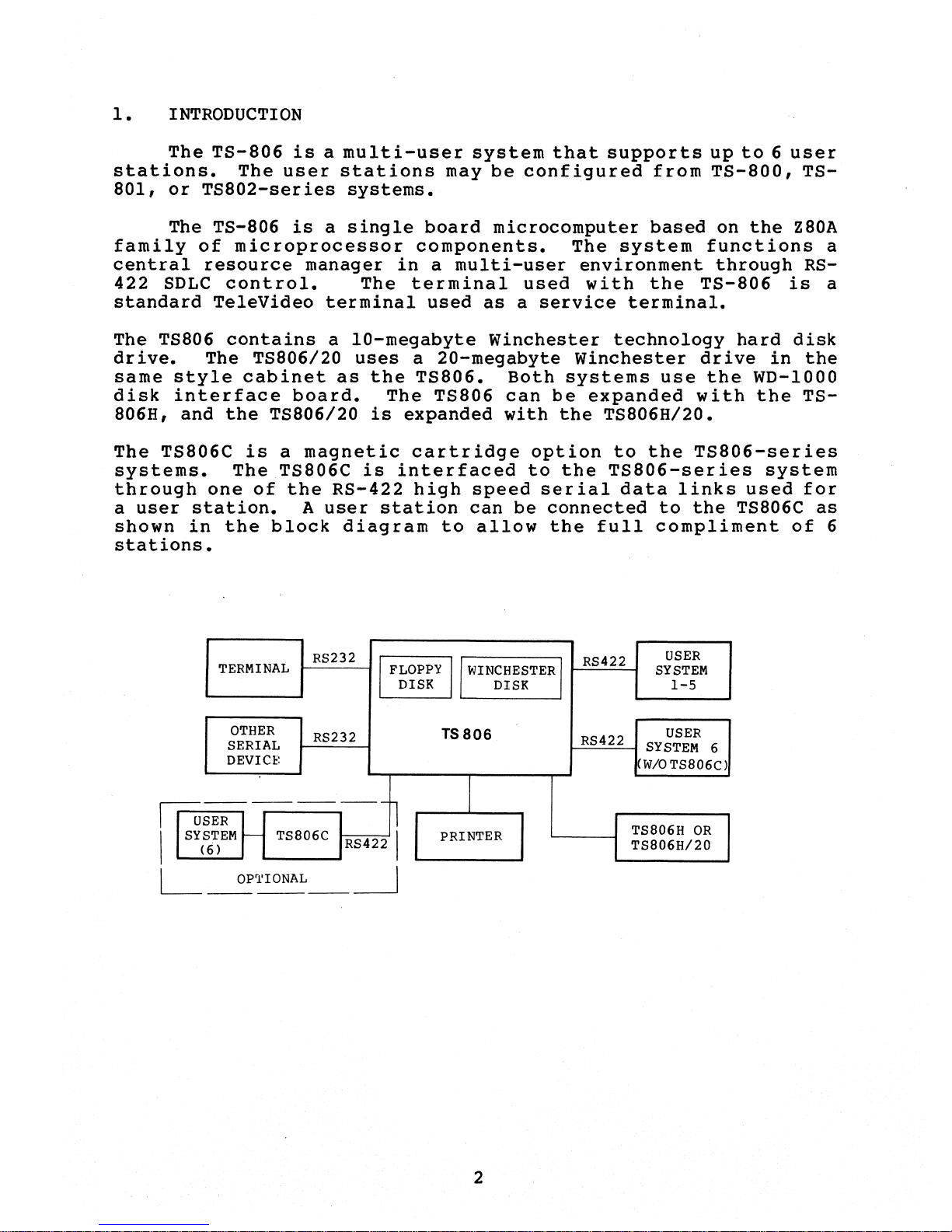
The
TS-806
is
a
multi-user
system
that
supports
up
to
6
user
stations.
The
user
stations
may
be
configured
from
TS-800,
TS-
801,
or
TS802-series
systems.
The TS-806
is
a
single
board
microcomputer
based
on
the
Z80A
family
of
microprocessor
components.
The
system
functions
a
central
resource
manager
in
a
multi-user
environment
through
RS-
422
SDLC
control.
The
terminal
used
with
the
TS-806
is
a
standard
TeleVideo
terminal
used
as
a
service
terminal.
The TS806
contains
a
10-megabyte
Winchester
technology
hard
disk
drive.
The
TS806/20
uses
a
20-megabyte
Winchester
drive
in
the
same
style
cabinet
as
the
TS806.
Both
systems
use
the
WD-lOOO
disk
interface
board.
The
TS806
can
be
expanded
with
the
TS-
806H, and
the
TS806/20
is
expanded
with
the
TS806H/20.
The
TS806C
is
a
magnetic
cartridge
option
to
the
TS806-series
systems.
The
TS806C
is
interfaced
to
the
TS806-series
system
through
one
of
the
RS-422
high
speed
ser
ial
data
links
used
for
a
user
station.
A
user
station
can
be
connected
to
the
TS806C
as
shown
in
the
block
diagram
to
allow
the
full
compliment
of
6
stations.
RS232
TERMINAL
I
FLOPPY
II
WINCHESTER
I
DISK
DISK
OTHER
RS232
SERIAL
DEVIn:
USER
-------l
rr=a
II
SYSTEM
t--
TS806C RS422 I
(6)
L
OP'l'IONAL
I
------~
TS806
I
PRINTER
2
USER
RS422
SYSTEM
1-5
RS422
USER
SYSTEM
6
W/OTS806C)
TS806H
OR
TS806H/20

2.
GENERAL
DESCRIPTION
a.
ZSOA-CPU
The
main
processing
unit
in
the
system
(4.0
MHz
operation).
b.
ZSOA-CTC
Counter/timer
chip,
generating
the
baud
rate
for
RS232C
serial
channel.
c.
ZSOA-PIO
Parallel
I/O
chip,
provides
centronics-type
printer
inter-
face.
d.
ZSOA-SIO
Serial
I/O
chips,
providing
RS232C
interface
(data
rate
to
19.2
KB)
and/or
RS422
high-speed
serial
interface
with
data
rate
of
SOOK
bit/sec.
e.
ZSOA-DMA
Direct
memory
access
controller
chip
is
used
for
direct
transfer
of
data
between
memory
and
peripheral
I/O
like
floppy
disk,
Winchester
hard
disk,
etc.
f.
Memory
Main
memory
available
to
user
is
64K
bytes,
using
64K X
1
DRAM
4K
bytes
of
ROM
and
lK
byte
of
SRAM
are
used
for
system
firmware
(used
on
power
up
or
reset
only).
g.
Floppy
disk
controller
Western
Digital's
FD
1793
chip
along
with
its
support
chips
WD
2143-01
and
WD169l
provides
control
and
interface
to
the
5
~"
floppy
drive.
h.
Winchester
hard
disk
interface
Interface
is
provided
to
the
disk
controller
board
for
the
5
~"
hard
disk.
3

3.
FUNCTION
The
facilities
available
to
the
users
are
64K
bytes
of
main
memory,
floppy
disk
controller
which
can
drive
potentially
up
to
4
drives
(0.5M
byte
each),
interface
to
communicate
with
the
hard
disk.
controller
which
can
also
drive
poten-
tially
up
to
4
hard
disk
drives
5
~"
Winchester,
and
parallel
port
for
high-speed
centronics-type
printer
interface.
2
channels
of
RS232C
type
interface
(from
1
SIO),
and
6
channels
of
RS422
interface
(from
the
other
3
SIO's)
to
communicate
with
the
user
systems
(TS-800,
TS-80l)
are
provided.
4Kbyt
es
of
ROM
and
lK
bytes
of
SRAM
are
used
for
system
initialization,
diagnostics,
boot,
and
floppy/hard
disk
control
during
the
power-up
or
reset,
and
are
not
acces-
sible
by
the
users.
After
the
initial
program
in
the
ROM
is
run
upon
power-up
or
reset,
the
dynamic
memory
area
(address
00-16
K
hex.)
is
switched
on
so
that
the
whole
64K
byte
of
main
memory
can
be
used
by
the
user.
TS-806
uses
a
DMA
controller
to
transfer
data
between
memory
and
I/O
devices,
memory
to
memory,
and
also
I/O
device
to
I/O
device.
A
CTC
chip
(A40)
is
reserved
to
provide
vectored
interrupt
capability.
Another
CTC
chip
(A39)
generates
(switch-
selectable)
baud
rates
for
RS232C
interface.
2
Channels
of
this
CTC
are
reserved
for
time-of-day
generation
as
a
user
implemented
option.
4
LED
indicators
are
used
for
diagnostic
purposes
to
in-
dicate
faults
in
the
hardware.
The
system
block
diagram
is
shown
in
Figure
2,
I/O
port
assignment
is
shown
in
Table
1
and
the
baud
rate
switch
configuration
is
shown
in
Table
2.
4

User
Optional.
{
FOC
l?ttet'rllpt
INT
CO?Itrollct
-For
Floppy
I
~~~~
&Hiud
DiSk
'-
MiJl;
-
Floppy
Disk
Dl'"ives
Winchester{
Htltd Disk
COJltrolier
Centronic- {
type
PriJl-ter
Interface
DRAM
64kX8
.l80A-DMA l80A-CPU
~O~l~AI
RATE
-eTC
#0
}RS232C
#1
}
RS232C
I--..II--l------""'.....J
#2
BAUD
RATE
t--L.-...J
SwrT~
'----v
LED'S
} RS422
"5
}
RS42.2
#6
DIAGRAM
2 -
BLOCK
DESIGN
OF
TS-806
5

ABUS
BIT
#
I/O
PORT
7 6 5 4 3 2 1 0 HEX.
0 0 0 0 0 X X X
00
Indicator
Load
(LED
Ref.)
0 0 0 1 0 X 0 0
lQ
510
1,
Ch A
Data
Reg.
1 0
12
Com/Stat
Reg
0 1
11
Ch B
Data
Reg.
1 1
13
Com/Stat
Reg
0 0 1 0 0 X 0 0
20
510
2,
Ch A
Data
Reg.
1 0
22
Com/Stat
Reg
0 1
21
Ch B
Data
Reg.
1 1
23
Com/Stat
Reg
0 0 1 1 0 X 0 0
30
510
3,
Ch A
Data
Reg.
1 0
32
Com/Stat
Reg
0 1
31
Ch B
Data
Reg.
1 1
33
Com/Stat
Reg
0 1 0 0 0 X X X
40
WDC
Reset
(Winchester
Disk
Soft
Reset)
0 1 0 1 0 X 0 0
50
510
0,
ChA
Data
Reg.
1 0
52
Com/Stat
Reg
0 1
51
Ch B
Data
Reg.
1 1
53
Com/Stat
Reg
0 1 1 0 0 X X X
60
Baud
Rate
Load
0 1 1 1 0 X X X
70
FDD
Select
1 0 0 0 0 X 0 0
80
CTC
Ch 0
0 1
81
Ch 1
1 0
82
Ch 2
1 1
83
Ch 3
1 0 0 1 0 X X X
90
DMA
1 0 1 0 0 0 0 0
AO
WDC
Reg.
0
Data
Reg.
0 0 1
Al
Reg.
1
Error
/liri
te
Precompensation
Reg.
0 1 0
A2
Reg.
2
Sector
Count
Reg.
0 1 1
A3
Reg.
3
Sector
Number
Reg.
1 0 0
A4
Reg.
4
Cylinder
Low
Reg.
1 0 1
AS
Reg.
5
Cylinder
High
Reg.
1 1 0
A6
Reg.
6
Size/Drive/Head
Reg.
1 1 1
A7
Reg.
7
Status/Command
Reg.
6

ABUS
BIT
#
I/O
PORT
7 6 5 4 3 2 1 HEX.
1 0 1 1 0 X 0 0
BO
FDC
Corn/stat
Reg.
0 1 B1
Track
Reg.
1 0 B2
Sector
Reg.
1 1 B3
Data
Reg.
1 1 0 0 0 X 0 0
CO
PIC Ch 0 (CTC)
User
Option
0 1 C1 Ch 1
1 0 C2 Ch 2
1 1 C3 Ch 3
1 1 0 1 0 X 0 0
DO
PIO
Ch A
Data
Reg.
1 0
D2
Corn/Stat
Reg
0 1
D1
Ch B
Data
Reg.
1 1
D3
Corn/Stat
Reg
1 1 1 0 0 X X X
EO
Enable
Dram
1 1 1 1 0 X X X
FO
Disable
Dram
Table
1.
I/O
Port
Assignment
7
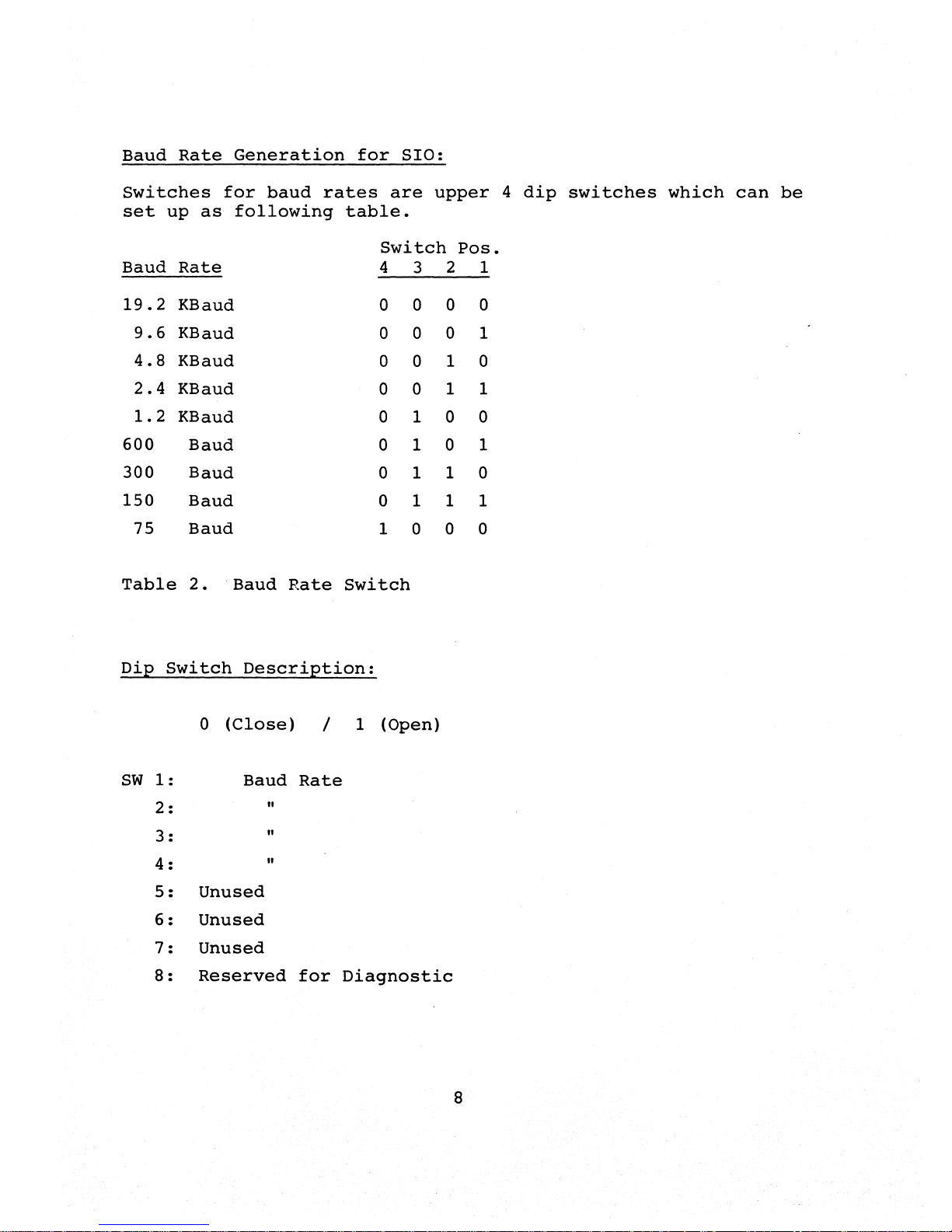
Baud
Rate
Generation
for
SIO:
Switches
for
baud
rates
are
upper
4
dip
switches
which
can
be
set
up
as
following
table.
Switch
POSe
Baud
Rate
4 3 2 1
19.2
KBaud
0 0 0 0
9.6
KBaud
0 0 0 1
4.8
KBaud
0 0 1 0
2.4
KBaud
0 0 1 1
1.2
KBaud
0 1 0 0
600
Baud
0 1 0 1
300
Baud
0 1 1 0
150
Baud
0 1 1 1
75
Baud
1 0 0 0
Table
2.
Baud
Rate
Switch
Dip
Switch
Description:
0
(Close)
/ 1
(Open)
Sw
1:
Baud
Rate
2:
"
3:
"
4:
"
5:
Unused
6:
Unused
7:
Unused
8:
Reserved
for
Diagnostic
8

4.
Circuit
Description
Generally
TS-806
circuitry
can
be
divided
into
8
sections
as
shown
in
Figure
3.
~
1.
Reset
5
2.
Clock
8[]
3.
Memory
---
4.
CPU
&
DMA
8
5.
Serial
I/O
6.
Floppy
Disk
Control
3 I I
2.
0
7.
Hard
Disk
Control
Ie]
8.
Printer
Interface
Figure
3
System
Board
Description
4.1
Reset
The
chip
associated
with
the
reset
circuit
is
a 74LSOO
(A2),
which
debounces
the
reset
signal
when
the
reset
switch
is
pressed.
A2-l3
is
normally
low
and
Pin
1
is
normally
high.
-Reset
must
be
active
for
at
least
three
clock
cycles
to
properly
reset
the
CPU.
As
long
as
-Reset
remains
active,
the
address
and
data
bus
float,
and
the
control
signal
outputs
are
in-
active.
The
CPU
returns
to
normal
operation
after
two
internal
"T"
cycles.
'-Reset
clears
the
PC
register
so
the
register
now
contain"s
a
value
of
0000.
4.2
Clock
Generation
16
MHz
signal
from
the
oscillator
(OSC)
is
divided
down
to
a 4
MHz
signal
using
a
93Sl6
(A7)
and
TR
2N2907
is
used
to
drive
the
proper
system
clock
level
and
again
buffered
for
enough
driving
current.
The
1
MHz
clock
from
the
93Sl6
is
supplied
to
the
floppy
disk
controller
chip
(FD
1793).
To
generate
the
baud
rate,
the
8
MHz
signal
from
the
93Sl6
is
fed
into
a
74LS163
(A8),
to
generate
the
frequency
of
1/6.5
times
the
system
clock
for
the
CTC.
Transmit
clock
for
the
SIO
(RS422)
is
generated
through
another
74LS163
(A38)
and
74S04
(A23)
using
system
clock.
9
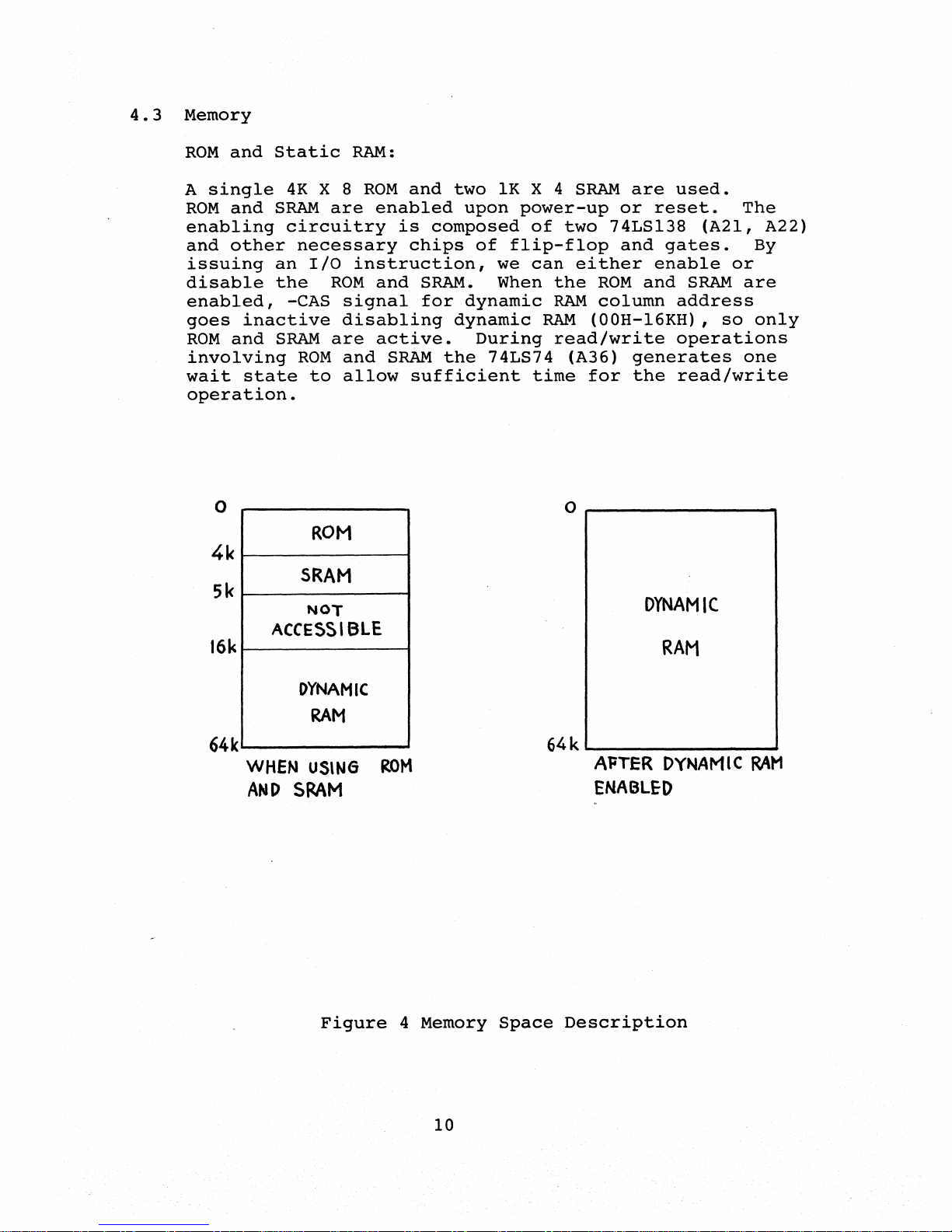
4.3
Memory
ROM
and
Static
RAM:
A
single
4K
X 8
ROM
and
two
lK
X 4
SRAM
are
used.
ROM
and
SRAM
are
enabled
upon
power-up
or
reset.
The
enabling
circuitry
is
composed
of
two
74LSl38
(A2l,
A22)
and
other
necessary
chips
of
flip-flop
and
gates.
By
issuing
an
I/O
instruction,
we
can
either
enable
or
disable
the
ROM
and
SRAM.
When
the
ROM
and
SRAM
are
enabled,
-CAS
signal
for
dynamic
RAM
column
address
goes
inactive
disabling
dynamic
RAM
(OOH-l6KH),
so
only
ROM
and
SRAM
are
active.
During
read/write
operations
involving
ROM
and
SRAM
the
74LS74
(A36)
generates
one
wait
state
to
allow
sufficient
time
for
the
read/write
operation.
o
4k
5k
16k
64k
ROM
SRAM
NOT
ACCESSIBLE
DYNAMIC
RAM
WHEN
USlNG
ROM
AND
SRAM
o
~--------------
__
DYNAMIC
RAM
64k~
________________
~
AFTER
DYNAMIC
RAM
ENABLEO
Figure
4
Memory
Space
Description
10

4.3
Eight
DRAM
chips
(64Kb
each)
are
used
for
main
memory.
Two
74S74
(A35,A37)
and
other
related
chips
(AI8,
A19)
are
used
to
generate
-CAS
and
-RAS
signals
using
-MI
and
-MREQ
signals.
Select
column
signal
chooses
either
AO-A7
or
A8-A15
as
row
and
column
address.
As
explained
previously,
when
dynamic
RAM
is
enabled
it
activiates
-CAS
signal
so
that
all
DRAM
locations
can
be
accessed
by
the
user.
During
refresh,
only
-RAS
signal
is
acti-
vated
and
one
whole
row
is
refreshed
at
one
time.
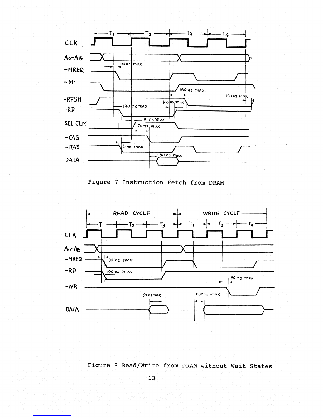
The
following
diagrams
show
the
timing
of
those
signals.
elK
Ao-AI5
-MREQ
-M!
-ROM
CE
-WAfT
-WR
f.--
145ns mQ.)(
-
~
-
--
IOOll~
mQ.x
--,
~
13011
m~x
-
~
-
~1\S
rn~x
'I
I--
~
HIGH
-SRAM
C
E
~1'\S
'YI'lOV<
--
, I
OATA
)(
n
r1/301\S
mo.x
I
I
'701'\5
me\)(
V
~
,01'1$
'11'\?\X
r ,
, r
Figure
5
Instruction
Fetch
from
ROM/SRAM
11

elK
I
READ
Cyel::: I
WRITE
CYCL~
J
I I
A
o-A/5 )(
MREQ
V
""'
v---
ROMCE
Y-
-GOns
7YI.
YI
DATA
1\
}-V
ROM
90
71S
'YVlo.x
-WR
-
--
--
"
IOOll~
111"
x
r-
-SRAH CS
1\
I--
23071S 1'l1"'X
DATA ,
I--
'701lS
'n'\
i71
-WAIT
\-
V
SRAM
Figure
6
Read/Write
on
ROM
and
SRAM
12
elK
Ao-AI5
-MREQ
-Hi
-RFSH
-RD
SEt
elM
-CAS
-RAS
DATA
ClK
Ao-I\s
--
~ns
m~)(
~
II
It-
ISO'1'lS
7Yl"'X
IOOl'l~
m",
/00
1I57n"'X'
--
.....
f..
I?O
llSm",X
--I
" -
I.--
9
'TlS
'l1lO\X
11
'70 'l1s
7Il"'X
--
~
"
'71~
m",x
-.I
90113
me).)(
If
,
\.
J
Figure
7
Instruction
Fetch
from
DRAM
-MREQ
----10..
-RD
-WR
DATA
Figure
8
Read/Write
from
DRAM
without
Wait
States
13

4.4
DMA
Operation
CLK
The
~DY
line
is
monitored
by
the
DMA
to
determine
when
a
peripheral
device
is
ready
for
read
or
write
operation.
When
the
DMA
is
enabled
the
ROY
line
indirectly
controls
DMA
activity.
-BUSREQ
is
used
as
output
from
the
DMA
chip
to
request
for
control
of
the
address,
data
and
control
bus
from
the
CPU.
If
CPU
receives
active
-BUSREQ,
the
CPU
will
set
these
buses
to
high
impedance
state
as
soon
as
the
current
CPU
machine
cycle
is
terminated,
and
then
sends
out
-BUSAK
signal
to
indicate
that
DMA
can
control
these
signals.
Figure
9
illustrates
the
-BUSREQ
and
-BUSAK (BAI)
timing.
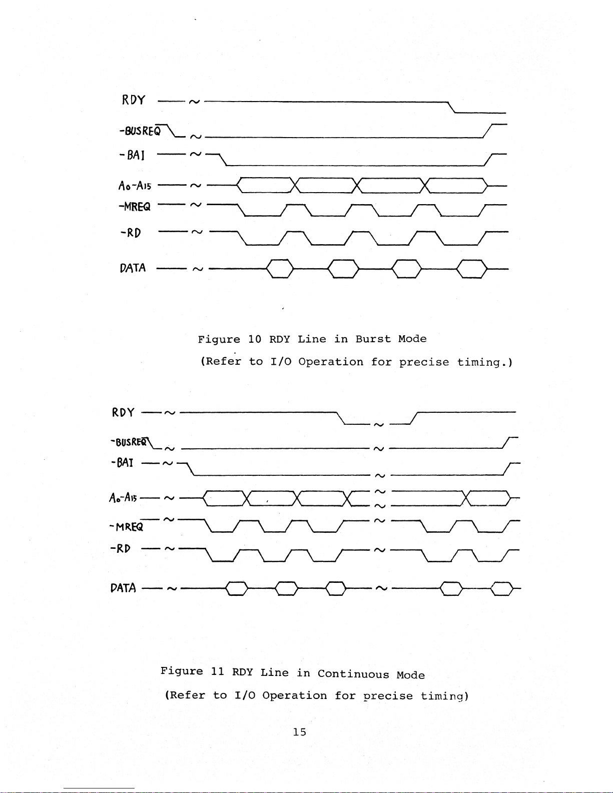
The
RDY
line
is
sampled
on
every
rising
edge
of
CLK
as
a
level,
not
an
edge.
When
the
DMA
detects
a
low
on
-BAI
line
for
two
consecutive
rising
edges
of
CLK,
the
DMA
begins
transferring
data
on
the
next
rising
edge
of
CLK.
Figure
10
and
Figure
11
explain
the
timing
diagram
of
RDY
line
in
burst
mode
and
in
continuous
mode
of
the
DMA.
RDY
-SUSREQ
~-----~----+------4--------~------~-----
-SAl
-------------------------~
D.MA
DMA
INACTIVE
ACTIVE
Figure
9
Bus
Request
and
Acceptance
Timing
14
RDY
--
rv
-------------------.\~
__
_
-BUSREQ\....
rv
______________
--'(
-BAI
-rv\
I
Ao-AI5
--
I"'J
("-
__
--'X"-
__
~X"_
__
--'X'__
__
__'>-
-MREQ
--
rv
-RD
--rv
DATA
--
rv
----<
Figure
10
RDY
Line
in
Burst
Mode
(Refer
to
I/O
Operation
for
precise
timing.)
RDY
-
"-J
------------,.
'---
'V
--.-I
-6USR~N
__________
_
"J
r
-BAY
-
""'
\"'-
________
_
"J
r
X
Ao-Als
-
""'
--{
X'--_--'
>c:
x:
r
rv
-rv
-MREQ
-RI>
-
~
DATA-~--......(
Figure
11
RDY
Line
in
Continuous
Mode
(Refer
to
I/O
Operation
for
precise
timing)
15
Table of contents
Other TeleVideo Desktop manuals

TeleVideo
TeleVideo 9320 User manual

TeleVideo
TeleVideo TVI-9128 User manual

TeleVideo
TeleVideo TS 806/20 User manual

TeleVideo
TeleVideo TPC I SYSTEM User manual

TeleVideo
TeleVideo 955 User manual

TeleVideo
TeleVideo TS 802H User manual

TeleVideo
TeleVideo 925 User manual

TeleVideo
TeleVideo 950 User manual

TeleVideo
TeleVideo TS-1605 User manual
Popular Desktop manuals by other brands

protech
protech PS-8931 user manual

RIGHT ANGLE
RIGHT ANGLE R-STYLE PLAN 110 Assembly instructions

Aqua Medic
Aqua Medic mV Operation manual

DAP Technologies
DAP Technologies V1214 user manual

Gym Master
Gym Master GateKeeper h5 Wiring instructions

Jason.L
Jason.L Litewall Workstation 4 Person Assembly instructions


