TeleVideo TS 802H User manual
TeleVideo@
TS B02H Computer System
Installation and User's Guide
TeleVideo No. B300015-001
Revision B
10 March 1982
Copyright
(c)
1982 by TeleVideo Systems, Inc. All rights reserved. No part
of
this publication may
be
reproduced,
transmitted, transcribed, stored
in
aretrieval system,
or
translated into any language or computer language,
in
any form
or
byany means, electronic, mechanical, magnetic, optical, chemical, manual, or otherwise, without the
prior written permission
of
TeleVideo Systems, Inc., 1170 Morse Avenue, Sunnyvale, California 94086.
Disclaimer
TeleVideo Systems, Inc. makes no representations
or
warranties with respect to this manual. Further, TeleVideo
Systems, Inc. reserves the rightto make changes
in
the specifications
of
the productdescribed within this manual
at any time without notice and without obligation
of
TeleVideo Systems, Inc. to notify any person
of
such revision
or changes.
"Warning: This equipment generates, uses, and can radiate radio frequency energy, and if not installed and used
in
accordance with the instruction manual may cause interference to radio communications. As temporarily per-
mitted by regulation, it has not been tested for compliance with the limits for Class Acomputing devices pursuant
to Subpart J
of
Part 15
of
FCC Rules, which are designed to provide reasonable protection against such interfer-
ence. Operation
of
this equipment
in
aresidential area is likely to cause interference,
in
which case the user at his
own expense will be required to correct the interference."
TeleVideo®
is
aregistered trademark
of
TeleVideo Systems, Inc.
Z80A® is aregistered trademark
of
ZILOG Corporation.
CP/M®
is aregistered trademark
of
Digital Resources, Inc.
Televideo
COBOLTM
is atrademark
of
TeleVideo Systems, Inc.
RM/COBOLTM
is atrademark
of
Ryan-McFarland Corporation.
TeleVideo Systems, Inc., 1170 Morse Avenue, Sunnyvale, California 94086 408/745-7760
TABLE OF CONTENTS
Page
LIST
OF
FIGURES
AND
TABLES
vi
1.
INTRODUCTION
1-1
1
.1
Introduction to this
Manual
1-1
1
.2
Limited Warranty
1-1
1
.3
Hardware Configuration
1-1
1
.4
Software Overview .....................................................
..
1-5
1
.5
Using
the
Manual
1-6
2.
INSPECTION
AND
INSTALLATION
2-1
2.1
Unpacking
2-1
2.2 Software Registration 2-2
2.3 Selecting the Right Location 2-2
2.4 Installation 2-4
2.5 Checklist of Installation Instructions 2-7
3.
OPERATION
3-1
3.1
Start
Up
3-1
3.2 Formatting
3-9
3.3
When
You
Are
Finished
3-9
4.
OPERATIONAL
GUIDELINES
.4-1
4.1
Working Near the System
.4-1
4.2 Caring for Diskettes
.4-2
4.3 Write-Protecting Diskettes .4-3
4.4 Backing
Up
the
Hard
Disk .4-3
4.5 Communicating with the System .4-4
4.6 Summary of Good Practices .4-4
5.
TERMINAL
OPERATION
5-1
5.1
Introduction
5-1
5.2 Turning
on
the Terminal
5-1
5.3 Keyboard Controls
5-2
5.4 Setting
up
the Terminal
5-7
5.5 Communicating with the Computer
5-9
5.6 Editing 5-10
5.7 Printing 5-10
6.
PROGRAMMING
6-1
6.1
Introduction
6-1
6.2 Monitor Mode !
6-1
6.3
User
and
Status Lines
6-1
6.4
Line
Lock
6-5
6.5 Disabling/Enabling the Keyboard
6-5
iii
TABLE OF CONTENTS
Page
6.6 Cursor Display 6-5
6.7 Keyclick
and
Bell
6-6
6.8 Smooth Scroll 6-6
6.9 Video Display 6-6
6.10 Visual Attributes 6-6
6.11
Special Graphics
6-8
6.12 Additional Memory 6-10
6.13 Auto
Page
6-10
6.14 Protect Mode 6-10
6.15 Normal
and
Reverse Linefeed 6-12
6.16 Cursor Control Codes 6-13
6.17
The
Function Keys
6-14
6.18
The
FUNCT
Key
6-16
6.19 Addressing
and
Reading the Cursor Position 6-16
6.20 Loading
an
Insert Character
6-17
6.21
Tab Programming 6-18
6.22 Communication Modes 6-20
6.23 Edit Keys 6-20
6.24 Editing Text
6-21
6.25 Clear Function
6-25
6.26 X-ON/X-OFF Control
6-25
6.27 Data Terminal Ready Control
6-25
6.28
Send
Function 6-26
6.29 Print Function Programming 6-29
7.
PREVENTIVE MAINTENANCE, TROUBLESHOOTING,
AND
SERVICE
7-1
7.1
Care.
........................................................
7-1
7.2 Troubleshooting
7-1
7.3 Changing the
Fuse
7-4
7.4 How to Get Service ................................................
7-5
7.5 Reshipping the
TS
802H
7-6
7.6 Technical Assistance
7-6
APPENDICES
A.
TS
802H Specifications ...................................................
A-1
B.
Statement of Limited Warranty
B-1
C.
Buying Additional Diskettes
C-1
D.
Suggested CP/M References
D-1
E.
Cable Specifications
E-1
F.
Pin
Connector Assignments
:..................
F-1
G.
Switch Settings
G-1
H.
Opening the System
Case
H-1
I.
Changing the
Pin
Connector Assignments
1-1
J.
Changing the Default
LST:
Device
J-1
iv
TABLE OF CONTENTS
Page
K.
Port Assignments
K-1
L.
Default Device Assignments
L-1
M.
TS 802H Utility Programs
M-1
N.
ASCII Code Chart
N-1
O.
Modifying CBIOS 0-1
INDEX
X-1
OPERATOR'S QUICK REFERENCE GUIDE X-4
v

LIST OF FIGURES
Page
1-1
Floppy
and
Hard
Disk Drives
1-2
1-2 Floppy Diskette
1-3
1-3 Diskette Inside Permanent Plastic Enclosure 1-3
1-4 Possible
TS
802H
Configurations
1-4
2-1
TS
802H
as
Packed
in
Container
2-1
2-2 Outside Dimensions 2-3
2-3 Cable Connector
2-4
2-4 Correctly Folded Excess Cable 2-4
2-5 Attaching Terminal Connector
2-5
2-6 Location of Switches
on
Rear
Panel
2-6
2-7 Plugging
TS
802H into
Wall
Outlet
2-7
3-1
Rear
Panel
3-1
3-2 Opening Floppy Drive Door
3-6
3-3 Removing Diskette from Jacket
3-7
3-4 Write Protecting Diskette ...................................................
3-7
3-5 Holding Diskette Before Insertion
3-8
3-6 Inserting Diskette
in
Floppy Drive
3-8
4-1
Diskette
and
Protective Lining Inside the Protective Black Plastic Enclosure
4-2
4-2 Write-Protected Diskette
4-3
4-3 Typical Back-up System
4-4
5-1
Rear
Panel
5-1
5-2 Keyboard Layout
..
5-2
5-3 Status
Line
Fields
5-8
5-4 Communications Flow
5-9
6-1
Video Attributes
and
Monitor Mode
6-3
6-2 Special Graphics
6-9
7-1
Display of Normal Self-Test
7-3
7
-2
Exterior
Fuse
Location 7-4
7-3 Good
Fuse
7-4
7
-4
Burned Out
Fuse
7-4
7
-5
Location of
Serial
Number
on
Rear
Panel
7-5
E-1
RS232C
E-1
E-2
RS422
E-1
G-1
Dipswitches 1through 5
Open;
6through 10 Closed. ...............................
G-2
H-1
Location of Screws
in
System
Case
.............................................
H-1
1-1
Location of Traces
on
Printed Circuit Board ........................................
1-1
vi

LIST OF TABLES
Page
1-1
TS
802H Ports 1-3
1-2 Disk Drive Assignments ...........................................
1-5
3-1
Hardware Error Abbreviations 3-6
5-1
Data Destination ..........................................................
5-1
5-2 Function of
Keys
5-3
6-1
Monitor Mode Control Characters
6-2
6-2 Cursor Coordinates 6-4
6-3 Visual Attributes
6-7
6-4 Escape Sequences for Visual Attributes 6-8
6-5 Screen Attributes
6-9
6-6 Effects of Auto
Page
and
Protect Mode
on
Linefeed Actions 6-12
6-7 Effects of Auto
Page
and
Protect Mode
on
Reverse Linefeed Actions 6-12
6-8 Cursor Control Commands 6-13
6-9 Default Function
Key
Values 6-15
6-10 Tab Controls 6-18
6-11
Edit
and
Insert Modes 6-22
6-12 Editing Commands 6-23
6-13 Clear Commands 6-25
6-14 Default Delimiter Values 6-27
6-15 Data Transmission Commands 6-27
6-16 Transmit Commands 6-28
7
-1
Troubleshooting Procedures 7-2
F-1
Connector Assignments for
P1
and
P2
F-1
F-2
P4
Connector Assignments
F-1
F-3
P4
Connector Assignments
F-2
G-1
Switch Settings
G-1
G-2
Communication Modes .......................................................
G-2
G-3
Printer
Baud
Rate
and
Terminal Baud Rate
G-2
J-1
Available Device Codes J-2
vii
1. INTRODUCTION
1.1
INTRODUCTION
TO
THIS MANUAL
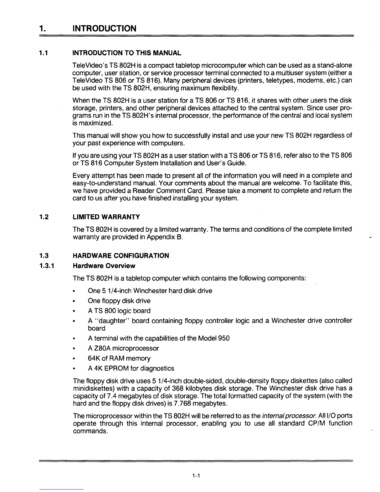
TeleVideo's TS 802H is acompact tabletop microcomputerwhich can be used as astand-alone
computer, user station,
or
service processor terminal connected
to
amultiuser system (either a
TeleVideo TS 806
or
TS 816). Many peripheral devices (printers, teletypes, modems, etc.) can
be used with the TS 802H, ensuring maximum flexibility.
When the TS 802H is auser station for aTS 806
or
TS 816, it shares with other users the disk
storage, printers, and other peripheral devices attached
to
the central system. Since user pro-
grams run
in
the TS 802H's internal processor, the performance
of
the central and local system
is maximized.
This manual will show you
how
to
successfully install and use your new TS 802H regardless
of
your past experience with computers.
Ifyou are using
yourTS
802H as auserstation with aTS 806
orTS
816, referalso
to
the TS 806
or
TS 816 Computer System Installation and User's Guide.
Every attempt has been made
to
present all
of
the information you will need
in
acomplete and
easy-to-understand manual. Your comments about the manual are welcome.
To
facilitate this,
we
have provided aReader Comment Card. Please take amoment
to
complete and return the
card
to
us after you have finished installing your system.
1.2 LIMITED WARRANTY
The TS 802H is covered by alimited warranty. The terms and conditions
of
the complete limited
warranty are provided
in
Appendix
B.
1.3 HARDWARE CONFIGURATION
1.3.1 Hardware Overview
The TS 802H is atabletop computer which contains the following components:
•One 51/4-inch Winchester hard disk drive
•One floppy disk drive
• A TS 800 logic board
• A
"daughter"
board containing floppy controller logic and aWinchester drive controller
board
• A terminal with the capabilities
of
the Model 950
• A Z80A microprocessor
•64K
of
RAM memory
• A
4K
EPROM for diagnostics
The floppy disk drive uses 5 1/4-inch double-sided, double-density floppy diskettes (also called
minidiskettes) with acapacity
of
368 kilobytes disk storage. The Winchester disk drive has a
capacity
of
7.4 megabytes
of
disk storage. The total formatted capacity
of
the system (with the
hard and the floppy disk drives) is 7.768 megabytes.
The microprocessorwithin theTS 802H will be referred to as the internalprocessor. All I/O ports
operate through this internal processor, enabling you
to
use
all
standard CP/M function
commands.
1-1

1.
INTRODUCTION
The integral terminal has anonglare screen and detached Selectric-style keyboard for the com-
fort
of
the user. Deluxe terminal features such as special graphics, visual attributes, and pro-
grammable function keys provide additional flexibility.
1.3.2
Disk
Drives
The TS 802H has one hard disk drive and one floppy disk drive.
Much like aphonograph, each floppy drive has ahead
or
arm which is lowered onto the disk or
diskettewheneverthe drivedooris closed, enabling the system
to
read
or
write information. The
disk head can move back and forth
("seeking")
as required
to
scan for information. The floppy
drive is located behind the dooron the upper lefthand side
of
the front
of
the case (Figure
1-1).
The head on the Winchester hard diskfloats overthe disk on acushion
of
air whenever poweris
on. The hard disk drive is located immediately below the floppy disk drive.
1.3.3
Disk
and
Diskettes
Application programs, text, data, and the programs which operate the TS 802H are stored on
the hard disk and floppy diskettes.
The drive heads automatically read both sides of thefloppy diskettes(Figure 1-2). The TS 802H
can use any floppy diskette which meets the specifications given
in
Appendix
C.
Newdiskettes
must be formatted before datacan be stored on them (as explained
in
3.2.1 and Appendix
M).
£LL[[[[[[
o
[I
II
Figure
1-1
Floppy
and
Hard Disk Drives
1-2

1. INTRODUCTION
01
]
o·
I
Figure 1-2 Floppy Diskette Figure 1-3 Diskette Inside
Permanent Plastic Enclosure
Each diskettehas amagneticcoating on both sides. Lubricants insidethis coverincreasethe life
of
the diskette. The actual diskette can be seen through some
of
the slots
in
the plastic cover.
Figure 1-3 shows the actual floppy diskette and protective lining inside the plastic cover. When
cared for as described
in
Chapter 4, diskettes can be reused many times.
When you insert the diskette
in
the drive and close the door, the drive spins the diskette (inside
thecover). Dataare stored on tracks
in
concentricrings on thediskette. The small opening
in
the
diskette cover near the center hole is areference point for the head while locating data. The
oblong opening
in
the diskettecover allows the head
to
retrieve information
in
batches.
1.3.4 Peripheral Devices
Three ports on the rear
of
the TS 802H allow you
to
connect peripheral devices as described
in
Table 1-1.
Table
1-1
TS
B02H Ports
Port Description
P2
(left)
P1
(right)
RS422
This RS232C
port
is
for
auser-supplied serial device such as a printer
or
amodem. This
port
is configured
for
aprinterwhen shipped from the factory, butcutting traces and making
jumperconnections allows amodem
to
be connected to this
port
instead.
This RS232C
port
may be configured
in
any
of
three ways:
1.
When shipped, this
port
is configured
for
use with amodem.
2.
Cutting traces and making jumper connections allows the TS 802H to be used with a
serial printer.
3. Changing adipswitch allows the TS 802H to be used as aservice processor terminal
with the TS 806/816 system console port.
This highspeed serial
port
connects the TS 802H to the TS 806
or
TS 816
for
use as a user
station.
1-3
1.
INTRODUCTION
TS
806/816
TS
802 H
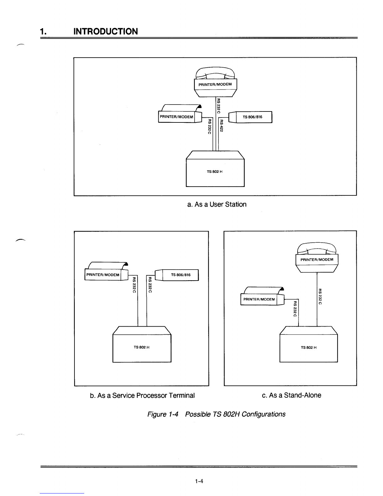
a.
As aUser Station
TS806/816
ill-.......JI.....-
-'
N
'"
N
(')
TS
802 H
b. As aService Processor Terminal
:Jl
CJ)
N
'"
N
(')
TS802
H
c. As aStand-Alone
Figure 1-4 Possible TS B02H Configurations
1-4

1. INTRODUCTION
1.4 SOFTWARE OVERVIEW
1.4.1 Operating System
Every computer needs instructions
in
order
to
operate; these instructions are supplied by a
group
of
programs collectively called the operating system.
Using dipswitches on the rear of the case, you can select one
of
three ways for the operating
system
to
be loaded intotheTS 802H, as described
in
Table 1-2. When theTS 802H
is
used
as
a
stand-alonecomputer, its operating system can be loaded into memoryfrom afloppydiskette
or
fromthe hard disk. When the TS 802H is auserstation foraTS 806/816, theoperating system
is
loaded from the TS 806/816. Table 1-2 shows the drive assignments for each configuration.
Source
Floppy
Hard
TS 806/816
Table 1-2 Disk Drive Assignments
Drive Maximum
Drive Physical
Capacity'
Directory
Assignments Device (Kilobytes) Entries
AFloppy 342 64
BHard2342 64
CHard 3488 5123
DHard 3488 5123
AHard 3488 5123
BHard 3488 5123
CHard2342 64
DFloppy 342 64
MFloppy 342 64
NHard2342 64
0Hard 3488 5123
PHard 3488 5123
Notes
1.
Excluding directory and operating system allocation
2. Simulated floppy drive
3.
Expandable
to
1024 using CBIOS
All TeleVideo computers use CP/M (Control Program for Microcomputers) Version X.X Operat-
ing System software, developed by Digital Research.
If
you
are
not
already familiar with CP/M, TeleVideo highly recommends that you refer to the
recommended reference books listed in Appendix Dandbecome familiar with the basic oper-
ation
of
the CP/Msystem.
1.4.2 Programming Languages
The TS 802H can use any programming language which will run under CP/M. Among these are
BASIC, ALGOL, APL,
"C,"
CBASIC, COBOL, FORTH, FORTRAN, MBASIC, PL/I, AND
RM/COBOL. When these languages are used with MmmOST, modifications which are de-
scribed
in
the MmmOST Programmer's Manual allow them
to
take advantage ofthe features
of
MmmOST.
In
addition, TeleVideo COBOL allows application programs
to
be used with
MmmOST with little
or
no modification.
1-5
1.
INTRODUCTION
1.4.3 Application Programs
Application programs are commercially available for awide range
of
tasks from accounting
to
security.
In
addition, you may write your own application programs
in
one
of
the programming
languages compatible with CP/M.
Programs written specifically to take advantage
of
the features
of
terminals other than Tele-
Video's Model 950
may
need to be modifiedsince the integral
TS
B02H terminal functions the
same as aModel 950.
1.5
USING
THE
MANUAL
1.5.1 Organization
Chapter 2will show you
how
to
unpack and install the TS B02H. Chapter 3will describe
how
to
operate the system. Chapter 4will suggest procedures for avoiding problems. Chapter 5ex-
plains
how
to
use the built-in terminal. Chapter 6explains
how
to
take advantage
of
the
TS B02H's terminal features
in
your programs. Chapter7tells
how
to
care for the TS B02H and
what
to
do
ifyou have aproblem with it.
In
the Appendices are the specifications, limited warranty, suggested references, and technical
information. The inside back covercontains the Operator's Quick Reference Guide, asummary
of
all control and escape commands used by the TS B02H's internal terminal.
1.5.2 Special Information
Notes call your attention
to
information which is
of
special importance.
Two
categories
of
notes
are used:
~
General note giving information
to
every operator.
•Note giving information concerning the safety
of
the operator
or
possible loss
of
..
data. When
you
see this, STOP
and
read the notebefore proceeding!
Your responses
to
system prompts will be indicated by bold print.
1.5.3 Format
of
Control Commands
The key marked
"CTRL"
on the keyboard is the CONTROL key.
To
use it, press it and hold it
down while you press another key (or keys). This combination is called acontrol command.
In
this manual, control commands will be shown as
1\
plus the control character (e.g.,
1\
G).
1.5.4 Carriage Returns
When you should press the RETURN key on the keyboard, the symbol
<CR>
for CARRIAGE
RETURN will be used. (On TeleVideo terminals, you can press the ENTER key instead
of
the
RETURN key.)
1-6
2.
INSPECTION
AND
INSTALLATION
2.1
UNPACKING
2.1.1 How
to
Unpack
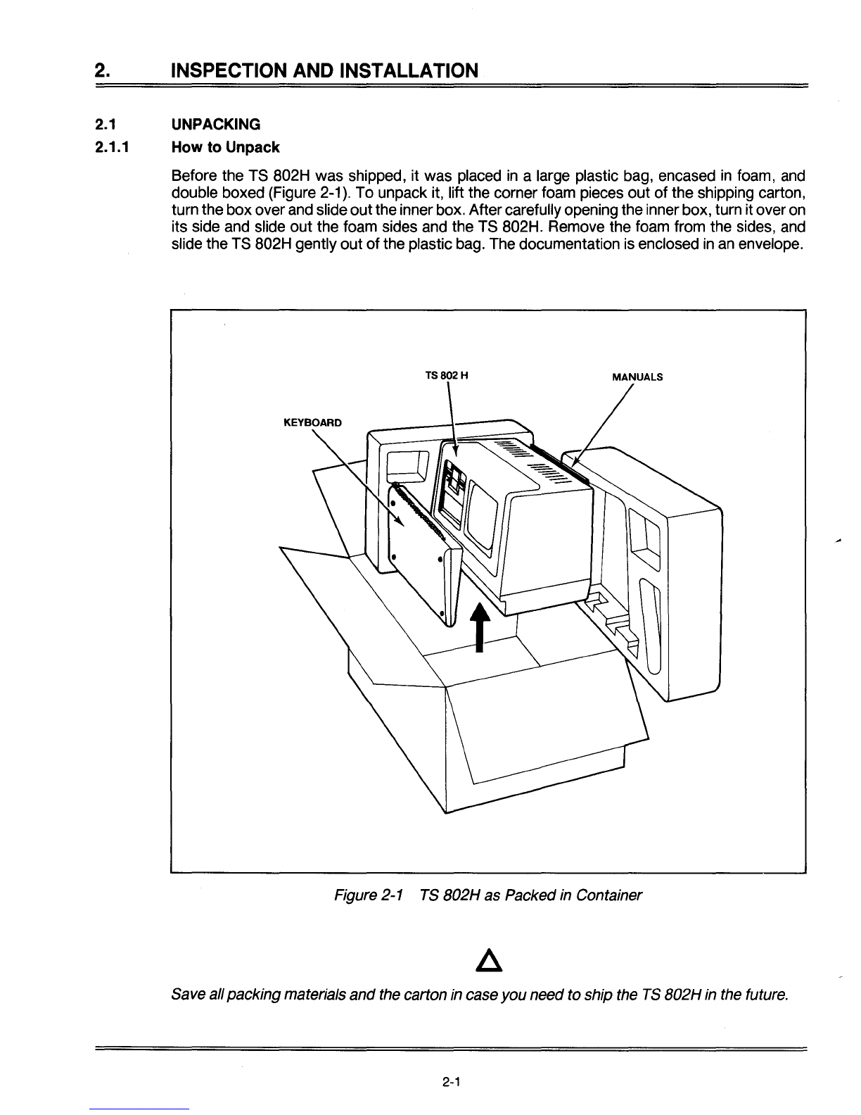
Before the TS B02H
was
shipped, it was placed
in
alarge plastic bag, encased
in
foam, and
double boxed (Figure 2-1). To unpack it, lift the corner foam pieces
out
of
the shipping carton,
turn the
box
overand slide
out
theinnerbox. Aftercarefully opening the inner box, turn it overon
its side and slide
out
the foam sides and the TS B02H. Remove the foam from the sides, and
slide the TS B02H gently
out
of
the plastic bag. The documentation is enclosed in an envelope.
TS802H
Figure 2-1 TS
802H
as Packed in Container
Save allpackingmaterials
and
the carton in case
you
needto ship the
TS
802H
in the future.
2-1
2.
INSPECTION
AND
INSTALLATION
2.1.2 Checklist of Components
As you unpack, check to make sure you received the following items:
1.
TS 802H
2.
Envelope containing the following items:
a.
Digital Research CP/M User Manual
b.
TS 802H Computer System Installation and User's Guide
c.
CP/M Licensing Agreement
d.
Two
5.25-inch floppy diskettes:
CP/M (system diskette)
CBIOS (source listing
of
system BIOS)
If
any item
is
missing, contactyourdealer before proceeding with the installation.
2.1.3 Shipping Damage
Check for shipping damage before proceeding with the installation. If the system case appears
to be damaged, contact your freight carrier immediately.
DO
NOT PROCEED WITH THE IN-
STALLATION
IF
YOU BELIEVE THERE WAS ANY SHIPPING DAMAGE. If
in
doubt, contact
your dealer as well as the freight carrier.
2.2 SOFTWARE REGISTRATION
Inside the front cover
of
the CP/M Manual that accompanies the system is the CP/M Software
License and License Agreement. Read the agreement and sign the card before opening the
package containing the diskette. Signing the agreement and returning the card will:
1.
Entitle you to use the CP/M operating system on your TS 802H and make back-up copies
for your own use
2.
Register you as aCP/M Owner, allowing you to receive:
a.
CP/M User's Newsletter
b.
Notices
of
updates and enhancements to Digital Research Software
c.
Digital Research Software bug reports and patches
d.
Discounts on updated versions
of
Digital Research software
2.3 SELECTING THE RIGHT LOCATION
2.3.1 Power Requirements
The TS 802H requires asteady supply of power:
115 VAC 60 Hertz (domestic) at 1.0 amp or230 VAC 50 Hertz (international) at 0.5 amp
2-2
2.
INSPECTION
AND
INSTALLATION
Incorrect
or
fluctuating line voltages can cause disk errors
or
damage the system.
If
you
have
any
doubt
about
the line voltages
at
your
location,
ask
your
dealer to check
out
your
facility
BEFOREPROCEEDING WITH THE INSTALLA
TION.
2.3.2 Physical Requirements
If the TS 802H is auser station connected
to
aTS 806/816, they should be within 300 feet
of
each other. If the TS 802H is being used as aservice processor terminal (service console) at-
tached
to
aTS 806/816, theyshould be within 50feet
of
each other. The printershould be within
50·feet
of
the TS 802H.
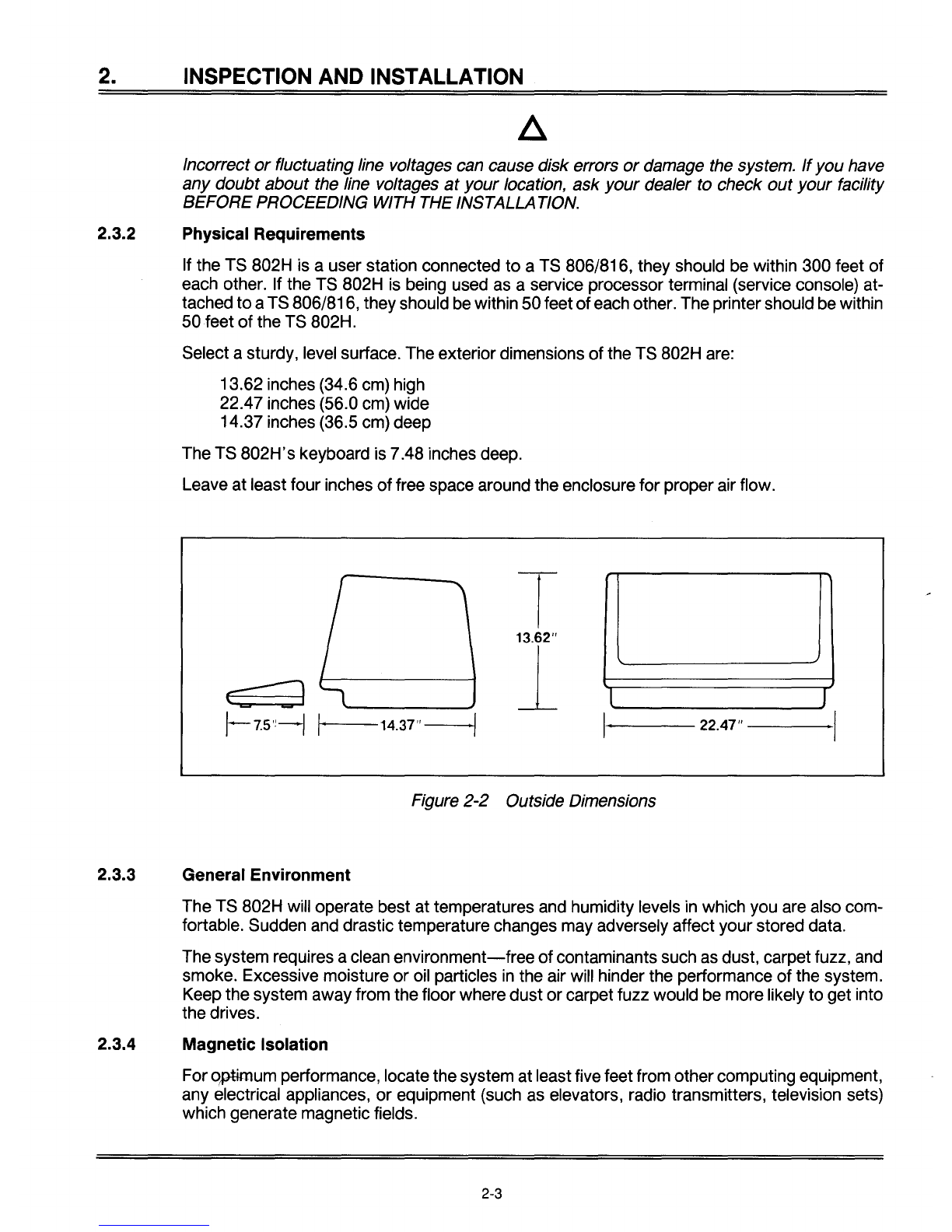
Select asturdy, level surface. The exteriordimensions
of
the TS 802H are:
13.62 inches (34.6 cm) high
22.47 inches (56.0 cm) wide
14.37 inches (36.5 cm) deep
The TS
802H's
keyboard is 7.48 inches deep.
Leave at least four inches
of
free space around the enclosure for proper air flow.
I
-I
13.62"
1
c=:J
~
lI
!-7.5'!-1
,. 14.37"
./
I·
22.47" I
Figure 2-2 Outside Dimensions
2.3.3 General Environment
The TS 802H will operate best at temperatures and humidity levels
in
which you are also com-
fortable. Sudden and drastic temperature changes may adversely affect your stored data.
The system requires aclean
environment-free
of
contaminants such as dust, carpet fuzz, and
smoke. Excessive moisture
or
oil particles
in
the air will hinder the performance
of
the system.
Keep the system away from the floor where dust or carpet fuzz would be more likely to get into
the drives.
2.3.4 Magnetic Isolation
Foroptimum performance, locate the system at least five feet from othercomputing equipment,
any electrical appliances,
or
equipment (such as elevators, radio transmitters, television sets)
which generate magnetic fields.
2-3
2.
INSPECTION
AND
INSTALLATION
2.4 INSTALLATION
General
directions for
all
installation configurations
are
given
in
this section.
The
next four sub-
sections give directionsfor installing a
serial
printeror
modem
(or otherperipheral
serial
devices)
and
connecting the T8
802H
(1)
to aT8 806 or T8 816
as
(a)
aservice processor terminal
(ser-
vice
console) or
(2)
auser station.
2.4.1 Cables
To connect the T8
802H
and
acentral computer, printer,
and
any
other peripheral device
(such
as
a
modem),
you
will
need
cables.
The
number
and
types of cables
needed
are
determined
by
the numberofdevices attached to the T8802H. Your dealer
can
supply
you
with the appropriate
cables.
(The
technical specifications for
each
type of
cable
are
shown
in
Appendix
E.)
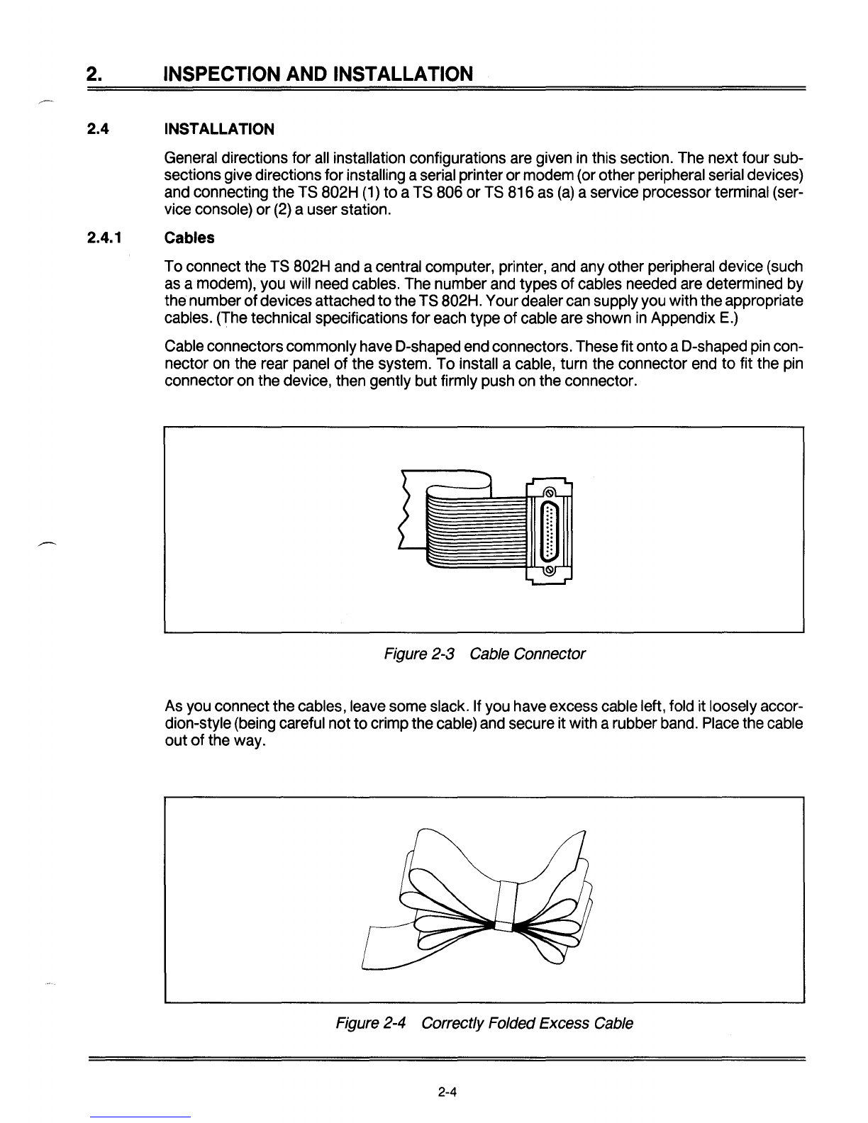
Cable
connectors commonly
have
D-shaped
end
connectors. These fit onto aD-shaped
pin
con-
nector
on
the rear
panel
of the system.
To
install a
cable,
turn the connector
end
to fit the
pin
connector
on
the device, then gently but firmly
push
on
the connector.
Figure 2-3 Cable Connector
As
you
connect the cables,
leave
some
slack.
If
you
have
excess
cable
left,
fold
it loosely accor-
dion-style
(being
careful not tocrimp the
cable)
and
secure it with arubber
band.
Place
the
cable
out of the way.
Figure 2-4 Correctly Folded Excess Cable
2-4
2. INSPECTION AND INSTALLATION
If
you are using aribbon cable, do notroll up excess cable. Rolled ribbon cable looks nice butit
creates an inductor
or
choke which can adverselyaffectsystem performance.
Also plug the keyboard cable into the rear panel.
2.4.2 Power Configuration
The system will be configured for your power requirements at the factory (either 115
or
230
VAC). Athree-prong plug
is
provided. If you use it with
an
adapter, ground itwith a"pigtail." The
powercord wires are color-coded as follows:
Green Earth ground
Black Primary power(hot)
White Primary power return (neutral)
2.4.3 Using the
TS
802H as aStand-Alone
If you use the TS 802H as astand-alone computer(Le., not as auser station for aTS 806/816),
nocable connections are necessary unless you wish
to
connect printers and/or modems
to
the
TS 802H. Check settings for S2 dipswitches as described
in
Appendix
G.
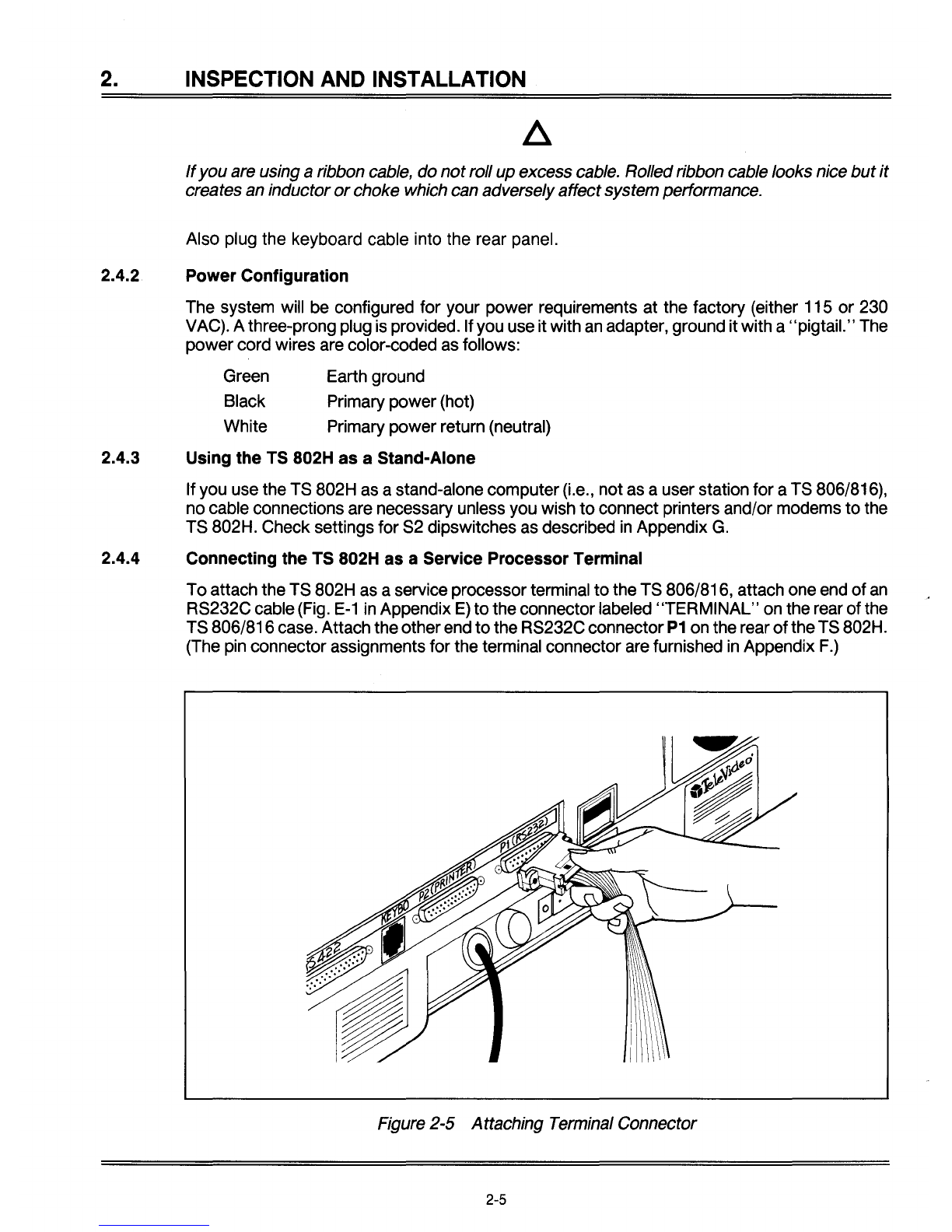
2.4.4 Connecting the
TS
802H as aService Processor Terminal
Toattach the TS 802H as aservice processor terminal
to
the TS 806/816, attach one end of
an
RS232C cable (Fig.
E-1
in
Appendix
E)
to
the connectorlabeled
"TERMINAL"
on the rear ofthe
TS 806/816case. Attach theotherend
to
the RS232C connector
P1
on the rear
of
theTS 802H.
(The pin connector assignments for the terminal connector are furnished
in
Appendix
F.)
Figure 2-5 Attaching Terminal Connector
2-5
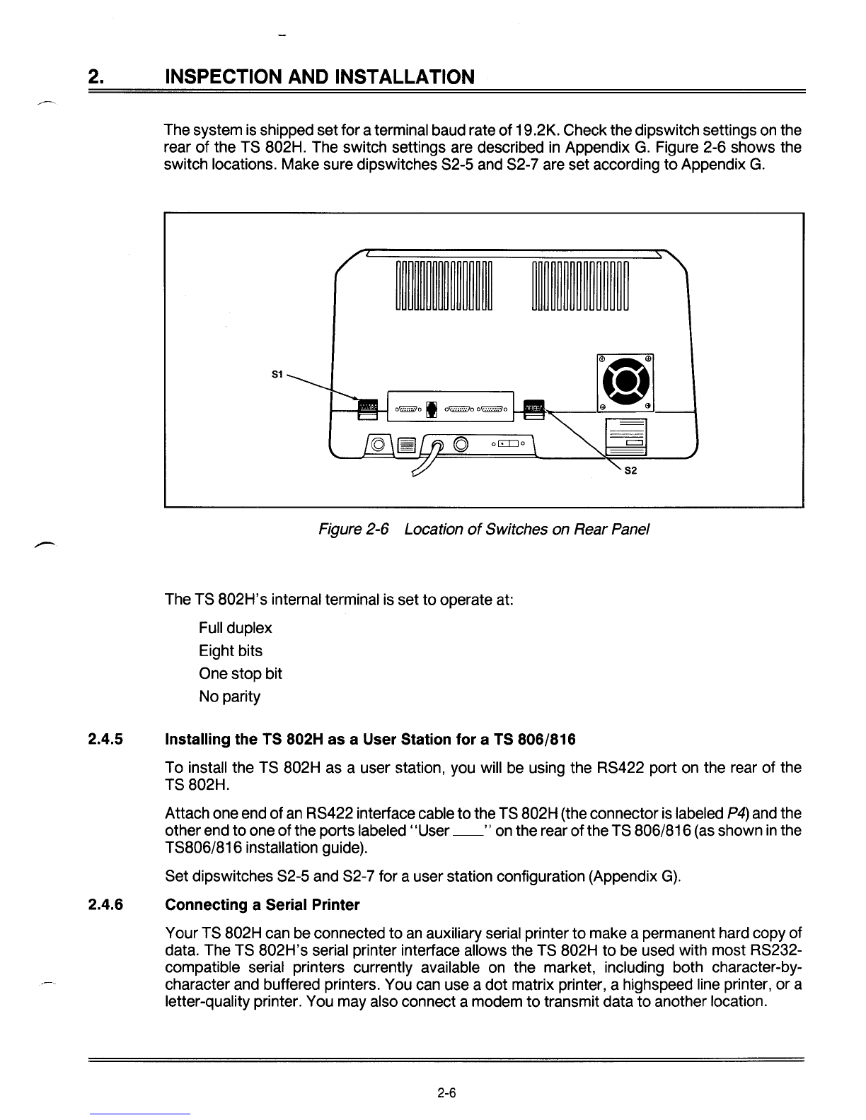
2. INSPECTION AND INSTALLATION
The system is shipped setforaterminal baud rate
of
19.2K. Check the dipswitch settings on the
rear
of
the TS 802H. The switch settings are described
in
Appendix
G.
Figure 2-6 shows the
switch locations. Make sure dipswitches S2-5 and S2-7 are set according
to
Appendix
G.
51
--
Figure 2-6 Location
of
Switches on Rear Panel
The TS 802H's internal terminal is set
to
operate at:
Full duplex
Eight bits
One stop bit
No parity
2.4.5 Installing the
TS
802H as aUser Station for a
TS
806/816
To
install the TS 802H as auser station, you will be using the RS422 port on the rear
of
the
TS 802H.
Attach one end
of
an
RS422 interfacecable
to
the TS 802H (the connectoris labeled
P4)
and the
otherend
to
one
of
the ports labeled" User
__
"on the rear
of
theTS 806/816 (as shown
in
the
TS806/816 installation gUide).
Set dipswitches S2-5 and S2-7 for auser station configuration (Appendix
G).
2.4.6 Connecting aSerial Printer
YourTS 802H can be connected
to
an
auxiliary serial printer
to
make apermanent hard copy of
data. The TS 802H's serial printer interface allows the TS 802H
to
be used with most RS232-
compatible serial printers currently available on the market, including both character-by-
character and buffered printers. You can use a
dot
matrix printer, ahighspeed line printer, or a
letter-quality printer. You may also connect amodem
to
transmit data
to
another location.
2-6
2.
INSPECTION
AND
INSTALLATION
The RS232C serial port labeled P2 is ready
to
use for aserial printer when the unit is shipped
from the factory. If this port and the otherRS232C port (labeled
P1)
are both used with printers,
cut traces on the printed circuit board and install jumpers (as described
in
Appendix
I)
before
attaching the RS232C interface cable.
Deviceassignments are given
in
Appendix
L;
addresses for RS232C portsare given
in
Appendix
K.
The second diskette included with the TS 802H
is
labeled CBIOS. This diskette allows you
to
modify the default printer device from one serial type
to
another
or
establish different power-up
default values. Instructions for modifying CBIOS are provided
in
Appendix
O.
2.4.7 Connecting aModem
You can connect one
or
two
modems
to
the TS 802H. The RS232C port which is labeled
P1
is
ready
to
interface
to
amodem.
This port is controlled bydipswitches which allow the TS 802H
to
be used with amodem or
as
a
terminal for aTS 806/816. Appendix Glists the switch settings which control this switch.
Toconnect
two
modems
to
theTS 802H, cuttraces on the printed circuit board and install jump-
ers
in
the pin connector of the port labeled P2(as described
in
Appendix
I)
before attaching the
RS232C interface cables.
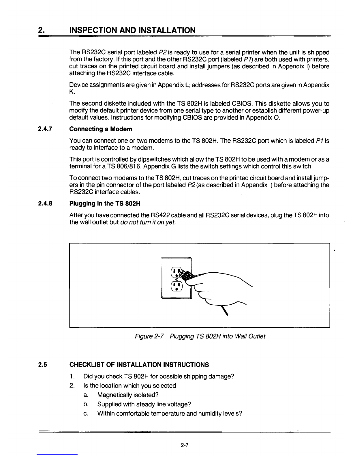
2.4.8 Plugging
in
the TS 802H
Afteryou haveconnected the RS422 cable and
all
RS232C serial devices, plug theTS 802H into
the wall outlet but
do
not
turn
it
on yet.
Figure
2-7
Plugging TS B02H into Wall Outlet
2.5 CHECKLIST OF INSTALLATION INSTRUCTIONS
1. Did you check TS 802H for possible shipping damage?
2.
Is
the location which you selected
a.
Magnetically isolated?
b.
Supplied with steady line voltage?
c.
Within comfortable temperature and humidity levels?
2-7

2.
INSPECTION
AND
INSTALLATION
d. Clean?
e.
Spacious enough for good ventilation around the case and
on
asufficiently large
table?
3.
Is
the power plug correct for your wall outlet?
4.
If the TS 802H is connected to aserial printer and/or TS 806/816, are they connected and
located within the distance limits specified?
5.
Did you set the switches for
all
peripheral devices? Did you make
all
necessary cuts and
jumpers?
6.
Did
you plug the TS 802H and peripherals into the wall outlet?
If the answer
to
all
of these steps
is
YES, then you are ready to use the TS 802H.
2-8
Table of contents
Other TeleVideo Desktop manuals

TeleVideo
TeleVideo TVI-9128 User manual

TeleVideo
TeleVideo TS-1605 User manual

TeleVideo
TeleVideo 955 User manual

TeleVideo
TeleVideo 950 User manual

TeleVideo
TeleVideo 925 User manual

TeleVideo
TeleVideo 9320 User manual

TeleVideo
TeleVideo TS 806H User manual

TeleVideo
TeleVideo TS 806/20 User manual

TeleVideo
TeleVideo TPC I SYSTEM User manual


