TeleVideo 950 User manual

~leVided
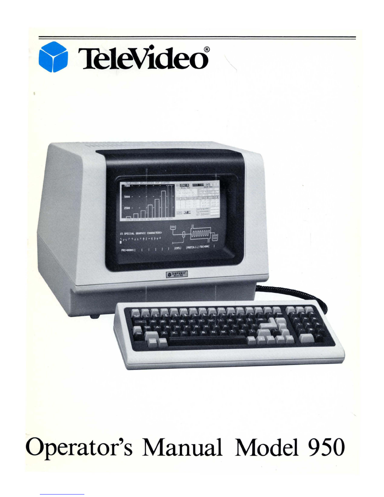
Operator's Manual Model 950

February,
1981
©Copyright Televideo,
1981
1981
TelVideo@ Inc.
Specifications and information subject
to
change without prior notification.
TeleVideo No. B300002-001

CONTENTS
Paragraph
Page
1.1
1.1.1
1.1.2
1.1.3
1.1.4
1.1.5
1.1.6
1.2
1.2.1
1.2.2
1.3
1.4
1.5
1.6
1.7
2.1
2.2
2.2.1
2.2.2
2.2.3
2.2.4
2.2.5
2.3
2.4
2.5
3.1
3.2
3.2.1
3.2.2
3.2.3
3.3
CHAPTER
1 GENERAL INFORMATION
INTRODUCTION.
. . . . . . . . . . . . . . . .
..
1-1
GeneralInformation.
. . . . . . . . . . . . . . .
..
1-1
FunctionalDescription. . . . . . . . . . . . . .
..
1-1
Operation.
. . . . . . . . . . . . . . . . . . . . . . . .
..
1-1
PerformanceVerification. . . . . . . . . . . .
..
1-1
Functional Description. . . . . . . . . . . . . .
..
1-1
Maintenance.
. . . . . . . . . . . . . . . . . . . . .
..
1-1
PRODUCT
DESCRIPTION.
. . . . . . . .
..
1-1
Additional
OEM
Features.
. . . . . . . . . .
..
1-1
Options
.............................
1-1
SAFETY
PRECAUTIONS.
. . . . . . . . .
..
1-1
RELATED
DOCUMENTATION. . . . . . . . . . . . . . .
..
1-2
SPECIFICATIONS.
. . . . . . . . . . . . . . .
..
1-2
LIMITED
AND
EXTENDED
WARRANTy
.......................
1-2
MANUFACTURER AND
AUTHORIZED
DEALER
SERVICES. . . . . . . . . . . . . . . . . . . . . . . .
..
1-2
CHAPTER
2 INSTALLATION
INTRODUCTION
...................
2-4
UNPACKING
AND
RECEIVING
INSPECTION.
. . . . . . . .
..
2-4
Shipping Damage
Inspection.
. . . . . . . .
..
2-4
Model950 Unpacking
.................
2-4
Enclosed Documents. . . . . . . . . . . . . . . .
..
2-4
InspectionProcedures
................
2-4
Reshipping Procedures
................
2-4
SITEPREPARATION
................
2-4
INSTALLATION
AND
SETUP
PROCEDURE
...............
2-4
INSTALLATIONCHECKS . . . . . . . . .
..
2-6
CHAPTER
3
OPERATION
INTRODUCTION
...
. . . . . . . . . . . . . .
..
3-8
REAR
PANEL CONTROLS
AND
CONNECTORSI
TURN-ON/TURN-OFF
PROCEDURE
.......................
3-8
Rear Panel Controls
and
Connectors . . . . . . . . . . . . . . . . . . . .
..
3-8
Turn-On Procedure. . . . . . . . . . . . . . . . .
..
3-8
Turn-Off
Procedure . . . . . . . . . . . . . . . .
..
3-8
DESCRIPTIONS
OF
KEYBOARD MODES
AND
FUNCTIONS
.......................
3-8
Paragraph
3.3.1
3.3.2
3.3.3
3.3.4
3.3.5
3.3.6
3.4
3.5
3.6
3.7
3.8
3.8.1
3.8.2
3.8.3
3.9
3.10
3.10.1
3.10.2
3.10.3
3.10.4
3.10.5
3.11
3.12
3.13
3.14
3.15
3.15.1
Alpha-Numeric Keys
.................
.
Editing
and
CursorControl Keys
.......
.
FunctionKeys
......................
.
SET-
UP
INO
SCROLLKey
..........
.
BREAK Key
........................
.
Key Modifiers
......................
.
KEYBOARD SETUP
PROCEDURE
......................
.
USER LINE
PROGRAMMING
.......
.
FUNCTION
KEY
PROGRAMMING
..................
.
CURSORATTRIBUTES
............
.
USINGTABS
......................
.
Typewriter Tabs
.....................
.
Field Tabs
..........................
.
Tab Operations
.....................
.
OTHER
MODE CONTROLS
.........
.
TEXT/DATA
CONTROL
MODES
................
.
Editing Text
........................
.
Inserting Text
.......................
.
Print
Control
.......................
.
SendFunction
......................
.
FunctionKeys
......................
.
OPERATING
IN
BLOCKMODE
.....................
.
OPERATING
IN
LOCALMODE
.....................
.
OPERATING
IN
HALF
DUPLEX
MODE
...................
.
OPERATING
IN FULL
DUPLEX
MODE
...................
.
PROGRAMMER'S
NOTES
AND
INFORMATION
..............
.
Communications Mode
and
Word Structure
.....................
.
3.15.2 Editing
and
Cursor Control
...........
.
3.15.3
Protect
Mode
.......................
.
3.15.4 Tab Programming
...................
.
3.15.5
Print
FunctionProgramming
..........
.
3.15.6 Send FunctionProgramming
..........
.
3.15.7 Video Attributes
....................
.
3.15.8 Special Graphics
....................
.
3.15.9 PageControl
.......................
.
3.15.10 ClearFunction
......................
.
3.15.11
MonitorMode
......................
.
3.15.12 InsertCharacter Loading
.............
.
3.15.13 Main
Port
Programming
.............
.
3.15.14 Printer
Port
Programming
............
.
3.15.15 X-ON, X-OFF, Control
..............
.
3.15.16 User
PROM
........................
.
3.15.17 Line Lock
..........................
.
3.15.18. Wraparound Feature
................
.
Page
3-9
3-11
3-11
3-12
3-12
3-12
3-12
3-13
3-13
3-13
3-14
3-14
3-14
3-14
3-14
3-14
3-14
3-14
3-15
3-15
3-15
3-15
3-15
3-15
3-16
3-16
3-16
3-16
3-17
3-17
3-19
3-19
3-21
3-21
3-22
3-22
3-22
3-22
3-22
3-22
3-24
3-24
3-24
3-24

Contents (continued)
Paragraph
Page
3.15.19 Video Display Control
................
3-24
3.15.20 Reference Tables
.....................
3-24
4.1
4.2
4.3
5.1
5.2
5.3
5.4
CHAPTER
4
PERFORMANCE
VERIFICATION
INTRODUCTION
...................
4-34
SELF-TEST 1
.......................
4-34
SELF-TEST2
.......................
4-34
CHAPTER
5 FUNCTIONAL DESCRIPTION
INTRODUCTION
...................
5-35
TERMINALOVERVIEW
.............
5-35
DISPLAY PROCESSOR
..............
5-35
KEYBOARD
AND
KEYBOARD
INTERFACE CIRCUITS
.............
5-35
List
of
Illustrations
Figure Page
2-1 Terminal Cabinet Receiving Inspection 2-5
2-2
115/230 V Select Switch 2-6
2-3
Host
Interface Connector Configuration for
Current Loop 2-6
2-4
Baud Rate, Word Length,
and
Stop Bit
Settings 2-7
2-5 Operating Mode Switch Settings 2-7
3-1 Model 950 Rear Panel Controls
and
Connectors 3-8
3-2
Model 950 Communications Modes 3-9
3-3 Model 950 Screen Display 3-10
3-4
Model 950 Keyboard 3-10
3-5 Model 950 Video Attributes
3-21
3-6
Model 950 Special Graphics Characters
3-21
4-1 Self Test 1 Screen Display 4-34
5-1 Model 950 Simplified Block Diagram 5-35
6-1 Keyboard Assembly Bottom 6-36
6-2
Power Supply Fuses 6-37
Paragraph
Page
5.5'
MAIN
INTERFACE
PORT
............
5-35
5.6
PRINTER
PORT
INTERFACE
........
5-35
5.7 DISPLAY GENERATOR
.............
6-36
5.8 VIDEO MODULE
AND
SCREEN
......................
6-36
5.9
POWER
SUPPLY. . . . . . . . . . . . . . . . . .
..
6-36
6.1
6.2
6.2.1
6.2.2
6.3
6.4
6.4.1
6.4.2
CHAPTER
6
OPERATOR
MAINTENANCE
INTRODUCTION
...................
6-36
PERIODIC
MAINTENANCE
.........
6-36
Cleaning. . . . . . . . . . . . . . . . . . . . . . . . . .
..
6-36
Inspection. . . . . . . . . . . . . . . . . . . . . . . . .
..
6-36
TROUBLESHOOTING. . . . . . . . . . . . .
..
6-37
REPAIR
............................
6-37
Line Fuse
...........................
6-37
PowerSupply Fuses
..................
6-37
List
of
Tables
Table Page
1-1
Specifications
1-3
2-1
Host
Interface Connector Configuration 2-6
2-2
Printer Connector Configuration 2-6
3-1 Monitor Mode Control Characters 3-23
3-2
USASCII
Chart
3-24
3-3 Model 950 Cursor Addressing Codes 3-25
3-4
Model 950 Control
and
Escape Codes 3-26
3-5 Alpha-Numeric Key Hex Codes 3-30
3-6
Cursor Control
and
Edit Key Hex Codes 3-32
3-7 Function Key Default Hex Codes 3-32
3-8 Local Only Keys 3-33
3-9
Key Action Modifiers 3-33
6-1 Model 950 Troubleshooting Check List 6-37

Chapter 1
GENERAL
INFORMATION
1.1
INTRODUCTION
This manual
is
a reference guide for the TeleVideo Mod-
el 950 Video Display Terminal operator. The informa-
tion presented in this manual will enable a Model 950
user to install, operate, program,
and
service the Video
Display Terminal. The manual contains the following
chapters:
Chapter
1.
General Information
Chapter 2. Installation
Chapter 3. Operation
Chapter 4. Performance Verification
Chapter 5. Functional Description
Chapter 6. Maintenance
The following paragraphs describe the contents
and
scope
of
these chapters.
1.1.1 General
Information
The General Information describes the Model 950 Video
Display Terminal, its features, and its applications.
In
addition, it provides general safety precautions, lists
documents related
to
the terminal,
and
lists the
terminal's mechanical and electrical specifications.
1.1.2 Installation
The Installation chapter provides detailed procedures
for unpacking
and
inspecting the Video Display Ter-
minal, interconnecting it
to
a host computer,
and
setting
up
operating parameters.
It
also includes procedures for
installation checks.
1.1.3 Operation
The Operation chapter contains detailed procedures for
operating the Model 950.
It
includes instructions for
turning the terminal
on
and
off
and controlling
and
pro-
gramming its many special features.
1.1.4 Performance Verification
The Performance Verification chapter contains proce-
dures for checking the terminal in all its operational
modes using the self-test feature.
1.1.5 Functional Description
The Functional Description chapter describes the overall
functional operation
of
the terminal based
on
a system
simplified block diagram.
It
also describes the functional
operation
of
the major circuits in the terminal, also based
upon simplified diagrams. The information contained
in this chapter provides the Model 950 user with
an
overall perspective
of
the terminal hardware.
1.1.6 Maintenance
The Maintenance chapter provides preventive mainte-
nance instructions and simplified procedures for troub-
leshooting terminal faults.
It
also contains procedures
for repairs most terminal users can make.
1.2
PRODUCT
DESCRIPTION
The TeleVideo Model 950 Video Display Terminal
is
a
compact state-of-the-art
"smart"
terminal
that
provides
high level performance
at
low cost. This terminal
is
com-
patible with most host computers and finds a wide vari-
ety
of
applications in the end user environment. Stan-
dard features include editing capabilities, protected
field, addressable cursor, line and character
insert/
de-
lete, upper
and
lower case characters,
and
tabbing. In
addition, the Model 950 provides the following standard
features:
Split screen with line lock
Etched
CRT
face to reduce glare
Programmable function keys
(11
keys with
22
functions)
15
special graphics characters
On-screen status (25th line)
Buffered auxiliary
port
14
x
10
character resolution
Attractive cabinet styling
Detached keyboard
Light weight for portability
Typewriter-styled keyboard
Dedicated editing keys
Maximum serviceability
Self test
1.2.1 Additional
OEM
Features
The Model 950 provides the original equipment manu-
facturer with several customizing features that include
Easy keyboard reconfiguration
Easy character reconfiguration
Reconfigurable firmware for Escape sequence
changes
Readily adaptable to packaging changes
Easily repainted keyboard
and
CRT bezels, and
cabinet
Easily replaced
CRT's
with differing phosphors
Accepts a variety
of
CRT color filters
Maximum serviceability
1.2.2 Options
The Model 950 may be ordered with several options that
enhance its already comprehensive list
of
features. These
options, available
at
additional cost, include
48
line memory that can be organized by the user in
either one 48-line page
or
two 24-line pages
96
line memory
that
can be organized by the user in
one 96-line page, two 48-line pages,
or
four 24-line
pages
Integral
modem/
dialer
1.3 SAFETY
PRECAUTIONS
As with any electronic equipment, precautions con-
sistent with all standard safety practices must be taken
while servicing the Model 950 Video Display Terminal.
Any servicing
that
requires opening the cabinet must be
performed by qualified service personnel. Prior to in-
spection or service, power must be disconnected.
Notices are included throughout this manual to alert the
reader
to
problem areas or situations that could cause
personnel injury, loss
of
data, or hardware damage.
A WARNING statement precedes the text
of
a procedure
1-1

that,
if
not strictly observed, could result in injury
or
death.
A CAUTION statement precedes the text
of
a procedure
that,
if
not strictly followed could result in the loss
of
data
or
damage to
or
destruction
of
equipment hardware
or
software.
A NOTE statement highlights essential operating
or
maintenance procedures, conditions, or clarifying facts.
NOTEs also provide information that helps the user un-
derstand a concept
or
the completion
of
a procedure.
The following are general safety precautions that are
not
related to any specific procedure and, therefore, do
not
appear elsewhere in this manual. Personnal must heed
these warnings during installation and maintenance.
WARNING
Keep Away
From
Live Circuits
Always observe safety precautions. Ob-
serve all the CAUTIONs andWARNINGs
in this manual when working inside the
terminal cabinet. Under certain condi-
tions, dangerous potentials may exist
when the power
is
off
because
of
charges
retained by the cathode ray tube (CRT)
and capacitors. To avoid injury, always re-
move power and discharge them to ground
before touching them.
Do Not Service
Or
Adjust Alone
Never reach into the terminal enclosure
unless someone capable
of
giving aid
is
present.
The following WARNING applies to any service inside
the terminal cabinet.
It
appears elsewhere in the text
of
this manual and
is
introduced here for emphasis:
WARNING
Hazardous voltages are exposed in the
cabinet. Use extreme caution when servic-
ing either the power supply, the cathode
ray tube,
or
any area where power ter-
minals are exposed.
1.4 RELATED DOCUMENTATION
This manual provides only that information necessary
for terminal installation, operation,
-and
user mainte-
nance. Other documents that may be helpful to the
Model 950 user include:
Operators Reference Handbook for Models
-912B,
912C, -920B, and -920C, TeleVideo No.
B300001-001
Model 950 Video Display Terminal Service Manual,
TeleVideo No. B300002-002
Models
912B,
912C, 920B, and 920C Maintenance
Manual, TeleVideo No. B300001-002
TeleVideo Commercial Price List
Model 950 Customizing Instructions
Televideo Spares Price List
TeleVideo Model 950 data sheets
These documents may be obtained from Televideo Inc.,
1170
Morse Avenue, Sunnyvale, California 94086.
1-2
1.5 SPECIFICATIONS
The mechanical, electrical, and environmental charac-
teristics
of
the Model 950 are listed in Table 1-1.
1.6 LIMITED AND EXTENDED WARRANTY
TeleVideo warrants that its products will be free from
defects in material and workmanship for a period
of
6
months from the date
of
shipment from the factory.
If
a
terminal
is
recei~ed
that has been damaged in shipment,
contact the carner and process a claim (Refer to para-
graph 2.2).
TeleVideo offers,
at
additional cost,
an
Extended War-
ranty Contract that warrants the Model 950 against de-
fects in material and workmanship for up to 1 year be-
yond the standard 6 month warranty. To be effective
this Extended Warranty must be purchased prior to
th~
expiration date
of
the standard warranty. The Extended
Warranty may be renewed for
an
additional year
at
the
current purchase price.
For
current Extended Warranty
Contract prices, contact your authorized TeleVideo
dealer or write to TeleVideo, Inc., at
1170
Morse
Avenue, Sunnyvale, California, 94086, attention Mana-
ger Customer Service.
1.7 MANUFACTURER AND AUTHORIZED
DEALER SERVICES
TeleVideo offers service to the end users
of
its products
that include:
1.
Authorized Dealer Repair
2. Factory Repair
3. User Replaceable Spare Parts
4. Service Documentation
If
you experience technical problems with a Model 950
call your TeleVideo Authorized Dealer.
If
the terminal should fail during the standard warranty
period, contact your local Authorized Dealer for assist-
ance.
If
your dealer finds that the repairs require re-
turning the terminal to the factory, a Return Material
Authorization number will be issued. Use this numberto
identify the terminal in all correspondence regarding the
repairs.
The terminal will be shipped to TeleVideo
at
the owner's
expense. Once the terminal
is
repaired, TeleVideo will
return
it
to its owner
at
no
charge via UPS surface. Any
other shipping arrangements, such as air express, will be
at
the owner's expense. Normal repairs require two days
plus transit time.
For out-of-warranty repairs, the same procedure must
be followed. The terminal owner
is
responsible for all
shipping charges and must issue a purchase order or
other written authorization for repair charges.
NOTE
Include a detailed description
of
the symp-
toms
of
the terminal malfunction when re-
turning it for repairs. Also include the
name and' telephone number
of
a responsi-
ble technical person that Tele
Video may
call in the event
of
any questions.
If
for any reason you are dissatisfied with either the
product or the service, please call the Manager
of
Customer Service, TeleVideo, Inc.

Display format
Character
format
Character
set
Cursor
control
Communications interface
Communication modes
Baud rates
Parity
Word structure
Screen attributes
Cursor
attributes
Editing
Auxiliary port
Communication protocol
Primary power
Cabinet dimensions
Keyboard dimensions
Cabinet weight
Keyboard weight
Ambient operating temperature
Relative humidity (operating)
Storage temperature
Relative humidity (non-operating)
Table
1-1
Specifications
24 lines x 80 characters 25th status line
14
x
10
dot
resolution with lower case descenders
128
character
ASCII
(96 alphanumeric + 32 control)
15
special graphics
Dedicated keys for left, right, up, down, home,
carriage return, line feed, tab, back
tab
RS-232C, 20mA current loop
and
optional
originatejauto-dial modem
Half duplex
or
full duplex (keyboard selectable),
10-
or
11-
bit word
Switch selectable: 50, 75, 110,
135,
150,
300, 600
1200,
1800,2400,3600,4800,7200,9600,
and
19,200
Odd, even, no parity, mark,
and
space (switch
and keyboard selectable)
7
or
8
data
bits, I
or2
stop bits
Dual intensity with protected fields, reverse video,
underline, blink
and
blank plus combinations
Programmable for reverse block, blinking reverse
block,
or
not displayed, underline,
or
blinking
underline
Line insertionjdelete; Line
or
page edit; character
insertionjdelete line lock; Line scrolling,
smooth
scrolling,
or
no
scroll,
or
insert mode
Printer RS-232C, bi-directional, page print, buffered
transparent, buffered with screen copy (Transparent
requires 48
or
96 line memory)
XON,
XOFF,
DTR
115
Vac, 60
Hzj230
Vac, 50 Hz; 6 5W
16.50" (41.9 cm) x 14.00" (35.6 cm) x 14.25" (36.2 cm)
16.50" (41.9 cm) x 7.50" (19.0 cm) x 3.00" (7.6 cm)
30 lbs. (13.6 kg)
4.5 lbs. (2.3 kg)
32°F
(O°C)
to
122°F (50°C)
10%
-95% non-condensing
No restrictions
1-3

Chapter 2
INSTALLATION
2.1 INTRODUCTION
This chapter contains procedures for installing the
Model 950 Video Display Terminal.
It
includes instruc-
tions for unpacking
and
inspecting, and procedures for
setup
and
for interconnecting the terminal
to
a hostcom-
puter.
2.2 UNPACKING AND RECEIVING INSPECTION
When a Model 950 Video Display Terminal
is
delivered
bya transfer company, it must be carefully inspected (in-
side the shipping container, as well as out) for damage
before taking it to the installation site.
If
the terminal
is
to
be reshipped, itmustbe repacked in a manner
that
will
prevent any damage
whHe
in transit.
2.2.1 Shipping Damage Inspection
Prior
to accepting delivery
of
the Model 950 Video Dis-
play Terminal from the carrier, carefully inspect the
shipping container for obvious damage.
If
damage
is
found, note it on the waybill
and
require the delivery
agent to sign the waybill. Notify the transfer company
immediately and submit a damage report to the carrier,
your dealer,
and
to
TeleVideo, Inc.
If
no exterior dam-
age exists, unpack the terminal and inspect for hidden
damage.
2.2.2 Model 950 Unpacking
The Model 9$0
is
shipped with the cabinet, keyboard,
and
Operator's Instruction Manual in the same shipping
container. The container
and
packing consists
of
a stur-
dy cardboard box and preformed styrofoam inserts.
Unpack the terminal from the shipping container with
care; avoid using sharp instruments to open the con-
tainer. TeleVideo recommends saving all packing mate-
rials for possible use in reshipping the terminal.
If
hidden damage
is
found, immediately notifythe trans-
fer company
of
the damage. Save all packing materials
for the transfer company's inspection, file a damage re-
port with the carrier, and notify your dealer and
TeleVideo, Inc.
of
the damage. Since Model950 terms
of
sale are F.O.B. TeleVideo Inc., Sunnyvale, California,
TeleVideo
is
not responsible for any damage incurred
during shipment,
nor
will TeleVideo repair this damage
under warranty. All repairs for shipping damage will be
billed.
Prompt
notification
of
damage will ensure claim
validity and will help·expedite payment for necessary
repairs by the transfer company or its insurance agent.
2.2.3 Enclosed Documents
A Model 950 Operator's Instruction Manual
is
shipped
with the Model 950 to provide operating and applica-
tions information, installation instructions, and service
information to the end user.
2.2.4 Inspection Procedures
After unpacking the Model 950, inspect it thoroughly
for damage hidden by the packaging and for loose com-
ponents or fittings, as follows:
2-4
WARNING
The coating
on
the inside
of
cathod ray
tubes
is
poisonous. Wear heavy rubber
gloves or use tongs (or a similar tool) to
pick up broken CRT fragments.
1.
Remove the keyboard
and
video dis-
play covers (see Figure 2-1).
2. Inspect the keyboard and the display
cabinet interior for shipping damage.
3. Examine cable harnesses for stress,
loose or broken wires,
or
broken cable
ties.
4. Examine internally mounted compo-
nents for loose
or
missing hardware.
5. Tighten all loose hardware.
6.
Clean the cabinet interior by removing
loose debris.
7. Replace the keyboard and video dis-
play covers.
2.2.5 Reshipping Procedures:
Should the Model 950 be reshipped to a distant location,
whether for reinstallation
at
a new site or for return to .
the factory for repair, proceed as follows:
1.
Remove the keyboard and video display cabinet
covers.
2. Check the integrity
of
the cabling and the secur-
ity
of
internal mounting hardware.
3. Repack the terminal in the original TeleVideo
shipping container
or
other suitable materials.
2.3 SITE PREPARATION
The Model 950 requires
115
Vac
60
Hz or 230
Vac
50
Hz
and
65
watts
of
power. A flat, level, mounting area
is
re-
quired. The installation site should have this power in
the immediate vicinity (in the U.S., a NEMA standard
5-15R, 3-prong receptacle). The cabinet requires
an
area
17.25" (43.8cm) high x 20.13" (51.1cm) wide x 24.06"
(61.1cm) deep. These dimensions allow 4inches
(1O.2cm)
for ventilation clearance.
2.4 INSTALLATION AND SETUP PROCEDURE
Installation and setup
of
the terminal consists
of
config-
uring for
115
Vac
of
230
Vac
operation, configuring and
installing the host
and
printer connectors, and setting up
the various operating paramenter switches. These proce-
dures should be performed only by technically qualified
personnel. To connect and set up the terminal for opera-
tion, proceed as follows:
1.
As required for international applications, cut
off
the US-style plug
on
the power cord and install a
connector that will mate to local power receptacles.
The power cord wires are color-coded as follows:
Green = earth ground
Black = primary power (hot)
White = primary power return (neutral)
2. Set the power select switch to
115V
or 230V (re-
move and reinstall the switch blocking strip as
necessary. (see Figure 2-2).
3. Configure the main interface connector accord-
ing to Table 2-1.

Terminal cover removed for inspection.
Keyboard cover removed for inspection.
Figure
2-1
Terminal Cabinet Receiving Inspection
2-5

4. Configure
the
host
interface connector with ac-
tive/passive
current
loop
connectors as required
for
the
loop
option
(see Figure 2-3).
5.
As
required, configure
the
printer interface con-
nector according
to
Table 2-2.
6. Set the desired
baud
rate,
word
length,
and
stop
bits
on
SI (see Figure 2-4).
7.
Set the desired operating modes
and
parity
on
S2
(see Figure 2-5).
8.
Connect
the
host
cable
to
the
RS-232C connector
on
the
cabinet
rear
panel.
9. As required, connect the
printer
cable
to
the
PRINTER
connector
on
the
cabinet
rear
panel.
10.
Connect
the terminal
to
primary
power.
2.5 INSTALLATION
CHECKS
Before turning the terminal
on
for
normal
operation
for
the
first time
after
installation, check each
of
the follow-
ing:
1.
Correct power plug installed
for
wall outlet?
2.
Power
selector switch set
for
local power? (see
Figure 2-2)
3.
Main
interface cable
to
host
computer
properly
wired
and
plugged in? (see Table 2-1)
4.
Current
loop
jumpers
installed,
if
needed? (see
Table 2-3)
5.
Printer
interface connector plugged in,
if
needed?
(see Table 2-2)
6.
Baud
rate set?
Stop
bits? Word Length?
Printer
baud
rate? (see Figure 2-4)
7. Desired operating modes set: key click,
50/60
Hz,
duplex/block/local,
black-on-white/white-on-
black, parity, cursor display, local
or
duplex edit? (see
Figure 2-5)
8. Terminal plugged
in
to
primary
power?
Table
2-1
Host
Interface
Connector
Configuration
PIN
No.
SIGNAL
NAME
1
Frame
Ground
2
Transmit
Data
Output
3 Receive
Data
Input
4 Request
To
Send
Output
5 Clear
To
Send Input
6
Data
Set Ready Input (opt.)
7 Signal
Ground
8 Carrier Detect Input
20
Data
Terminal Ready
Output
9
20
rnA
source (+
12V,
no
load)
14
20
rnA
source (+
12V,
no load)
10
Detected current loop
data
25
Current
Loop +, Transmit*
13
Current Loop -, Transmit*
12
Current
Loop +, Receive*
24
Current
Loop -, Receive*
*Refer to Figure 2-3 for connector configuration.
2-6
Table 2-2
Printer
Connector Configuration.
PIN
No.
1
2
3
4
5
6
7
8
20
115/230V
SELECT SWITCH
SIGNAL
NAME
Protect
Ground
Transmit
Data
Receive
Data
Request
To
Send
Clear
To
Send
Data
Set Ready
Signal
Ground
Data
Carrier Detect
Data
Terminal Ready
STRIP BLOCKING
SWITCH
Figure 2-2 115/230V Select Switch
FDX
ACTIVE PASSIVE
==fl
B
+ 25
-:
~
A
9 20
mo
SOURCE
25 + TRANSMIT CURRENT
+ 13 • TRANSMIT CURRENT
- 7 GROUND
TRANSMIT
lOOP
RECEIVE
lOOP
c
14
20
m.
SOURCE
/'
12 + RECEIVE CURRENT
+-
24
• RECEIVE CURRENT
7 GROUND
10 DETECTED CURRENT
lOOP
DATA
3 RCV DATA IN
CONNECTIONS IN ANY COMBINATION:
A+C
B+O
A+OorB+C
14
12
24
10
HDX
ACTIVE PASSIVE
25
13
14
12
10
Figure 2-3
Host
Interface Connector
Configuration for Current
Loop
25
13
14
12
24
10
o

!
----
OPEN
----
1 2 3 4 5 6 7 8 9
10
UP
DOWN
~I
I'
f 'PRINT
BAUD
R~TE
_
STOP
BIT
(UP -
2,
DOWN -1) ,
..
,"
_____
,_
"--------
WORD STRENGTH (UP =
7;6~WN
=
8~
"-----------
TERMINAL
BAUD
RATE
l
SWITCHES
BAUD
RATE
I
7 8 9
10
PRINTER
1
234
TERMINAL
000
0 9600
1
000
50
o 1 0 0 75
1 1 0 0 110
001
0 135
101
0 150
o 1 1 0 300
1 1 1 0 600
000
1 1200
1 0 0 1 1800
o 1 0 1 2400
1 1 0 1 3600
o 0 1 1 4800
1 0 1 1 7200
o 1 1 1 9600
1 1 1 1 19200
0=
DOWN
1 =
UP
Figure 2-4 Baud Rate, Word Length,
and
Stop Bit Settings
----
OPEN
----
2 3 4 5 6 7 8 9 10
UP
DOWN
~II
LKEY
CLICK
(UP = OFF,
DOWN
= ON)
50/60Hz (UP = 60Hz, DOWN = 50Hz)
MODE
"-------
REVERSE VIDEO (UP =
WHITE
ON
BLACK
SWITCH
345
- - 0
001
o 1 1
1 0 1 '
1 1 1
'---------PARITY
DOWN =
BLACK
onWHITE)
"-----------CURSOR
DISPLAY (UP =BLINK, DOWN = STEADY)
"-------------
EDIT (UP = DUPLEX, DOWN =
LOCAL)
PARITY
NO
ODD
(RECV and XMIT)
EVEN (RECV and XMIT)
MARK
(Xmit parity disabled)
SPACE (Xmit parity disabled)
SWITCH
MODE
7 8
o0 HALF DUPLEX
o1 FULL DUPLEX
1 0
BLOCK
1 1
LOCAL
NOTE: Set 50/60Hz the same
as
the power line
frequency
to
avoid display
flicker
Figure 2-5 Operating Mode Switch Settings
2-7

Chapter 3
OPERATION
3.1 INTRODUCTION
This chapter describes the Model 950 keyboard.
It
also
provides power-on procedures and instructions for nor-
mal operation.
For
the programmer, this chapter in-
cludes complete information
on
Escape
and
Control
Code sequences, graphics character generation,
and
special feature control. As a reference aid
to
experienced
programmers, all tables pertinent to operation are
at
the
end
of
this chapter:
NOTE
All Escape and Control Code sequences
are shown with a space between each char-
acter.
These
spaces
are
notpart
oj
the code
sequence. Thespaces are included for clar-
ityonly.
3.2 REAR PANEL CONTROLS AND CONNECTORS
I TURN-ONI TURN-OFF PROCEDURE.
The following paragraphs describe the location and
function
of
the controls and connectors
on
the Model
950 rear panel, and provide procedures for turning the
terminal
on
and
off.
3.2.1 Rear Panel Controls and Connectors.
The controls on the Model 950 rear panel(see Figure 3-1)
I , , , , I I , • • • • •
are the
PO
WER
switch, the
CONTRAST
control, and
the
BAUD
RATE
and
FUNCTION
setup switches. The
rearpanelconnectorsare the main interface
port
(P3
RS-
232C)
and
theprinter
port
(P4
PRINTER)
and
keyboard
connector
PI.
TheFUSEholder contains a fuse thatpro-
tects the internal circuitry against shorts.
3.2.2
Turn
On
Procedure.
To
turn
on
the Model 950, proceed as follows:
1.
Push the end
of
the rocker power switch marked
with a white dot. The terminal bell will beep within 1
second indicating that power
is
on.
2. After
10
to
15
seconds, the cursorwill appearinthe
upper left corner
of
the screen,
and
thestatus line will
appear across the bottom
of
the screen
on
line 25.
3. Adjust the
CONTRAST
control for the desired
screen intensity.
4. Follow the sign-on protocol required by your
system.
3.2.3
Turn
Off
Procedure.
To
turn
off
the terminal, proceed as follows:
1.
Follow the sign-off (or equivalent) protocol re-
quired by your system.
2. Push the unmarked end
of
the rocker power
switch.
3.3 DESCRIPTIONS OF KEYBOARD MODES
AND FUNCTIONS.
The Model 950 Video Display Terminal consists
of
a
video display processor that receives input from a host
........., , , ,
III1IIIIII1I1 III1IIII1III1
Figure
3-1
Model 950 Rear Panel Controls and Connectors
3-8

computer
and
a keyboard for presentation
on
a
CRT
screen.
Data
is
input
to
the processor in serial through
RS-232C standard ports. The keyboard although laid
out
like a standard typewriter, contains additional keys
for communicating with a computer. Unlike a typewriter
(where pressing a key results directly in a typed
character), the Model 950 keyboard transmits a code
(American Standard Code for Information Interchange.
ASCII) to the display processor for action. Depending
on
the terminal's communication mode, the processor
either sends the typed character directly to the screen
or
transmits it
to
the host for action.
NOTE
What the hostcomputersends back to the
Model 950
(if
anything) depends entirely
on the application program in use. Refer
to your application program user docu-
mentation for complete information.
The Model 950 may be set
to
one
of
four transmission
modes. In the Local mode (see Figure 3-2), the display
processor sends keyboard entries directly to the screen
for presentation (characters)
or
for control. The Block
mode sends keyboard entries to the screen,
and
when the
operatorchooses, it sends the entries as a block
of
text
to
the host computer. The
Half
Duplex mode sends key-
board entries
to
the screen
and
to the host
at
the same
time. The Full Duplex mode sends keyboard entries
to
the host only;
if
the host
is
programmed
to
act
upon
a
code received from a keyboard entry, it may send the
result back
to
the terminal. For example
if
the A
is
pressed
on
the keyboard, the host will probably send the
character A back to the terminal's display processor for
writing
on
the screen.
The Model 950 displays data entered from the keyboard
or from a host computer into the terminal
on
an
80 col-
umn by
24
line screen (see Figure 3-3). A 25th line
at
the
bottom
of
the
display presents terminal status
and
user
messages.
Data
entered into the terminal
is
organized in
pages
of
24 lines (or optional 48-line
or
96-line pages).
These pages may be flipped through with the linefeed
function (using
Auto
Page)
or
a page selection control
sequence.
A printer with
an
RS-232C serial data port may be con-
nected to the Model 950 to print page data stored in
memory
or
to print
data
sent from the host.
The controls
of
the Model 950 consist
of
the keyboard
for normal operation (see Figure 3-4) and setup switches
at
the rear panel for configuration (see Figure 2-5). The
keyboard consists
of
six functional areas: the alpha-nu-.
meric keys, the editing and cursor control keys (local
or
duplex operation), the function keys (local
or
duplex
operation), the SET-
UP/NO
SCROLL
key (a unique
function
-local
operation only), Local Escape
and
shift
Break (local operatiop only), the
BREAK
key (Full
Duplex only), and the key modifiers.
3.3.1 Alpha-Numeric Keys.
The alpha-numeric key group (see Figure 3-4) contains
all the "typewriter" letter, number, and symbol keys
on
the keyboard. This group also contains the carriage
RETURN,
LINEFEED,
ENTER,
LOC
ESC/ESC,
and
DEL
keys. All alpha-numeric keys repeat when pressed
for more
than
Yz
second.
TheRETURN
and
ENTER
keys performthesame func-
tion
..
They send the
ASCII
code for a carriage return
(CR)
to
the display processor. Depending
on
the termin-
al's communication mode, the code causes the processor
to
transmit a
CR
to
the host
and
the cursor
to
be moved
to
column 1
of
the current line.
NOTE
The Model 950 features a wraparound
function, which eliminates the need
to
manually enter a carriage return
and
a
line-feed
at
the end
of
each SO-character
line.
The
LINEFEED
key sends
an
ASCII
code for a linefeed
(LF)
to
the display processor. Depending
on
the termin-
al's communication mode, the code causes the processor
to transmit
an
LF
code to the host
and/or
the cursor
to
be moved down one line
on
the screen.
The
ESC
key sends
an
ASCII
code for Escape
to
the dis-
play processor. The key
is
generally used
to
momentarily
leave (escape)
an
application program in order to use a
special feature
or
function.
Whenpressed,
ESC
causes the next controlcharacteren-
tered to be displayed
on
the screen.
For
example, press-
ing
ESC
CTRL
A causes SH
to
be displayed.
Whenpressed incombinationwithSHIFT, thekey oper-
ates only locally to invoke the terminal's functions
and
special features.
It
causes the next character entered
to
be interpreted as a command. For example, pressing
SHIFT
LOC
ESC
< turns keyclick
off
and pressing
SHIFT
LOCK
ESC>
turns keyclick on.
The
DEL
key sends
an
ASCII
DEL
character to the dis-
playprocessor, and depending
on
the terminal's commu-
nication mode, the processor retransmits an
ASCII
DEL
code to the host.
~
---
FROM KEYBOARD
~
- - - - TOfFROM HOST
r-::l
D
I
L-----
1
------8
DISPLAY
PROCESSOR
3-9

Figure 3-3 Model 950 Screen Display
Figure 3-4 Model 950 Keyboard
3-10
LINE 25
STATUS LINE
TERMINAL
BAUD RATE

3.3.2 Editing and Corsor Control
K.eys
The cursor control keys
(t,
1,
-,
-,
BACKSPACE,
and
HOME)
normally control cursor movement
on
the
screen. The editing keys (see Figure 3-3) control insert
and delete characters
and
lines and clear functions. The
PRINT
and
SEND
keys control data transmission from
the screen
to
the printer
or
host computer.
When set
to
the Local Edit mode (paragraph 3.10.1), the
keys affect only the current page. They are
not
trans-
mitted to the host. When set
to
the Duplex Edit mode,
the keys operate in the same mode as the alpha-numeric
keys by transmitting their associated control code
or
es-
cape sequence
and/
or perform their action locally. The
editing
and
cursor control keys are:
1.
TAB
and
BACK
TAB
2.
CHAR
INSERT
and
CHAR
DELETE
3.
LINE
INSERT
and
LINE
DELETE
4.
LINE
ERASE
and
PAGE
ERASE
5. BACKSPACE,
HOME,
t,
1,
-,
and-.
6.
CLEAR
SPACE.
7.
SEND
and
PRINT.
All keys except
LINE
ERASE,
PAGE
ERASE,
CLEAR
SPACE, HOME, SEND, and
PRINT
repeat when
pressed for more
than
Yi
second.
a. Tab Control Keys.
TAB
(ESC
i)
and
BACK
TAB
(ESC I) move the cursor forward
or
backward to type-
writer tabs (Protect mode off)
or
to the next start
or
previous start
of
an
unprotected field (Protectmode on).
b. Character Insert Keys.
CHAR
INSERT
(ESC
Q)
en-
ters the insert character (refer to paragraph 3.15.13)
at
the cursor position, causing all succeeding characters to
shift one position to the right.
If
the terminal
is
set
to
the
EditLine mode (EDTL-wraparoundturnedoff), char-
acters shifted
off
screen to the right are lost.
If
the ter-
minal
is
set to the EditPage mode (EDTP-wraparound
turned
on-refer
to
paragraph 3.10.1), characters shift-
ed beyond column
SO
are moved to the first column
of
the next line. When
CHAR
INSERT
is
pressed
at
the
same time as SHIFT, the Insert mode (ESC q)
is
turned
on
(INSL
or
INSP
on
the status line).
c.
Character Delete
Key.
CHAR
DELETE
(ESC W) de-
letes the character
at
the cursor position and causes all
succeeding characters to shift one position
to
the left.
If
the terminal
is
set
to
the Edit Line mode
(EDTL-wrap-
around turned off), the character position
at
the end
of
the line
is
replaced with the insert character.
If
the ter-
minal
is
set to theEdit Page mode (EDTP-wraparound
turned on), characters from the first column
of
the next
line are shifted into the last positions
on
the current line.
When
CHAR
DELETE
is
pressed
at
the same time as
SHIFT, the Insert mode (ESC r)
is
turned
off
(EDTL
or
EDTP
on
the status line).
d. Line Insert
and
Delete Keys. The
LINE
INSERT
(ESC E) key creates
an
entire line
of
insert characters
on
the cursor line. The
data
on
the cursor line and all fol-
lowing lines shift down one line (the last line
of
the page
is
lost).
LINE
DELETE
(ESC
R)
causes the entire line
at
the cursor position to be deleted. All the following lines
shift up one line.
When
LINE
INSERT
or
DEL
is
pressed
at
the sametime
as SHIFT, Edit page (refer
to
paragraph 3.10)
is
turned
on
(ESC
N)
or
off
(ESC
0),
respectively.
e. Line Erase
and
PageErase Keys.
LINE
ERASE
(ESC
T) and
PAGE
ERASE
(ESC
Y)
replace the unprotected
data(from the cursorthe end
of
theline
or
page) with the
insert character
of
the proper intensity.
When the keys are pressed
at
the same time as SHIFT,
they cause a line erase
to
nulls (ESC t)
or
a page erase to
nulls (ESC y).
f. Cursor Control Keys. When set to the Local mode,
theBACKSPACE,
t,
1,
-,
and
-keys
move the cursor in
the directions indicated
on
the key cap.
HOME
moves
the cursor tothe first unprotected position
on
thecurrent
page.
g. Clear Space
Key.
CLEAR
SPACE
(CTRL
Z)
replaces
all unprotected characters
on
a page with insert charac-
ters. When pressed
at
the same time as
SHIFT
(ESC *), it
clears the entire page to nulls and turns
off
the Protect
and
Half
Intensity modes.
h.
Print
Key.
PRINT
causes all data
on
apage from the
home position to the cursor position(notjustthe screen)
to be output through the terminal printer port. The data
is
output with a CR, LF, and null automatically inserted
at
the end
of
each SO-column line
(PRT
0)
or, when
PRINT
is
pressed
at
thesame time as SHIFT, withoutthe
CR, LF,
or
null
(PRT
1).
PRINT
operates either as a
local function
or
as a duplex function (like theedit keys).
When the terminal
is
outputtingdatathrough the printer
port,
PRT
0,
PRT
1,
PRT
2,
PRT
3,
or
BDIR
(bidi-
rectional) appears
on
the Status Line.
PRT
2 indicates
the Transparent
Print
mode, in which data output from
the host
is
sent
to
the printer portand
to
thescreen.
PRT
3 indicates that data output from the host
is
sent directly
to the printer, bypassing the screen.
BDIR
turns
on
two-
way communication through the printer port to allow
conversation between a printer with a keyboard (a KSR
device)
and
the host.
PRT
2,
PRT
3, and
BDIR
are print
modes generally turned
on
by the host (through prepro-
gramming), although they may be turned
on
at
the key-
board.
CAUTION
If
the terminal
is
set to
PRT
2 by the host,
pressing
PRINT
or
SHIFT
PRINT
cancels
PRT
2
(PRT
3
is
not
affected). This could
interrupt the host output to the printer
at
the wrong moment, resulting in a loss
of
data.
L Send
Key.
Data
may be sent
to
a host from the Model
950 by several methods in order toconformtothe editing
mode
of
the terminal. These methods are single charac-
ter, line, and page. Inaddition, eitherall data
or
only un-
protected data can be selected for transmission. The
method used depends
on
the terminal's setup for the
system it
is
in (refer to paragraph 3.15.6b for program-
ming information).
3.3.3 Function Keys
The function keys (see Figure 3-4),
Fl
throughFll
(refer
3-11

to
Figure 3-1), are user defined. When pressed, the keys
cause the processor
to
send a user-defined code
to
the
screen,
to
the host,
or
to
both, depending
on
whether the
key was set
up
for Local
or
Duplex mode.
For
example,
the user-defined code may consist
of
a frequently used
Escape
or
Control code sequence in a text editing ap-
plication.
Up
to
22 codes may be defined-two
per
key.
Pressing
SHIFT
at
the same timeas a function key trans-
mits the second code
on
the key.
The
FUNCT
key transmits a user-selected character
bracketed
by
Control A (SOH)
and
a Carriage Return
(CR).
For
example,
if
a Control A C
CR
sequence is re-
quired
for
a special operation
in
a text editing program,
pressing
FUNCT
and
C
at
thesametime transmits CON-
TROL
A C
CR
to
the host automatically.
3.3.4
SET-UP/NO
SCROLL
Key
The
SET-UP/NO
SCROLL
key (see Figure 3-4) pro-
vides control
of
two independent functions
of
the Model
950: stopping screen updating during normal operation
and
manually setting the operating characteristics
of
the
terminal.
a. No Scroll Function. During normal operation, the
No-Scroll function
of
the
SET-UP/NO
SCROLL
key
is
active. When pressed, the terminal stops updating the
screen. When pressed again, the terminal starts updating
the screen.
If
the receive buffer fills
up
while update is
disabled, X-OFF will be sent
to
the host computer, caus-
ing it
to
stop sending data. When update
is
re-enabled,
the buffer will empty, causing X-ON
to
be sent
and
data
to
be transmitted
by
the host.
b. Setup Function. The
SET-UP/NO
SCROLL
key is
used to manually set the terminal's operating charac-
teristics. The setup function is enabled by pressing
SHIFT
and
SET-UP/NO
SCROLL
at
the same time.
The
characteristics are as follows:
1.
Edit
mode-Provides
for text
to
be changed
on
a
line (EDTL)
or
page (EDTP) basis.
2. Insert
mode-Provides
for text
to
beinserted
on
a
line (lNSL)
or
page (lNSP) basis.
3. Keyboard lock (KLOK)-When on, deactivates
the keyboard (except for the SET-Up,
LOCK
ESC,
BREAK,
and
function keys).
4. Protect mode (PROT)-Causes all half-intensity
characters
to
be protected from change.
5.
Half
Intensity (H.I.)
mode-Causes
all subse-
quently entered characters
to
be displayed
at
half in-
tensity.
6. Transmission
mode-Local
(LOC), Block (BLK),
Half-Duplex (HDX),
and
Full-Duplex (FDX). Refer
to
paragraph 3.3.
7. Terminal operating baud rate (same selections as
in Table 1-1).
The status
of
these characteristics
is
displayed
on
the
Status Line (line 25).
3.3.S
BREAK
Key
The
BREAK
key (see Figure3-4) causes the Model 950
to
transmit a 250-ms break pulse
to
the host. The effect
of
this signal depends
on
the operating program.
3-12
When pressed
at
the same time as SHIFT,
BREAK
per-
forms a limited terminal reset byclearing the function
in
progress.
It
turns
off
the
Print
mode
if
on, turns
off
Half
Intensity
and
Protect
modes~
and
sounds thebell tone
to
indicate the reset.
3.3.6
Key
Action Modifiers
The control keys
of
the Model 950 (see Figure 3-4) are
conventional
and
include control (CTRL), SHIFT,
and
ALPHA
LOCK. These keys by themselves have
no
ef-
fect
on
theterminal
or
host; however, whentheyareused
in combinationwith other keys, they change (or modify)
thecodesent
to
theterminalprocessorfor the key pressed.
a. Control
Key.
The
CTRL
key modifies the code sent
by
another
key.
When pressed at the same time as an-
otherkey, thekeyboardsends a uniquecode.
The
control
key combinations are used for special functions
of
the
Model 950
and/or
of
the application program
of
the
host.
For
example, a
CTRL
G key combination sounds
the Model 950 bell. The Model 950 control codes either
duplicate existing dedicated keys
on
the keyboard
or
control functions normally controlled by the host, such
as turning
on
the bidirectional printer
port
(refer
to
paragraph 3.15.5)
or
sounding the bell.
b.
SHIFT
Key.
The
SHIFT
key functions similar
to
the
CTRL
key by modifying the code sent by another key
pressed
at
the same time. The most familiar use
of
this
key is
to
produce upper case characters
on
the screen.
However, it is also used in combination with the dedi-
cated keys
of
theterminal for special functins.
For
exam-
ple, pressing
SHIFT
and
SET-UP
together enables
or
disables the setup mode
of
the terminal (refer
to
para-
graph 3.4).
c.
ALPHA
LOCK
Key.
The
ALPHA
LOCK
key locks
the
SHIFT
keys so
that
all alpha keys transmit codes for
upper-case characters. The key is pressed
to
lock
and
pressed again
to
release.
3.4 KEYBOARD
SETUP
PROCEDURE
When the Model 950
is
first turned on, it reads setup
default values (from rear panel switches S1
and
S2-refer
to
paragraph 2-4)
and
displays some
of
them
on
the Status Line (see Figure 3-3).
In
some cases, the
operator may reset these values locally (the values may
be set by the host
computer-refer
to
paragraph3.15.13
and
3.15.14). To set these values, proceed as follows:
1.
Push
SHIFT
and
SET-UP
at
the same time. The
cursor will immediately appear in the eight block
(EDTL)
on
the Status Line.
2. Press T
to
toggle through the editing controls
(EDTL, EDTp, INSP, and
INSL)
to
the desired selec-
tion.
3. Press to move the cursor
to
the next Status Line
block.
4. Press T
to
lock the keyboard (KLOK). The key-
board should be locked when the terminal is
to
beleft
on
and
unattended for short periods
of
time.)
5. Move the cursor
to
the next Status Line block
and
press T for the Protect mode.
6. Move the cursor
to
the next Status Line block
and
press T for the
Half
Intensity (H.I.) mode.

7. Move the cursor to the next block and toggle
through the operating mode controls (LOC, BLOCK,
HDX,
and
FDX)
to the desired selection.
8.
If
the terminal
is
to operate temporarily
at
a baud
rate different from the default value set
on
the setup
switches (refer to paragraph 2.4), move the cursor
to
the next setup block and press T
to
toggle through the
baud rates to the desired value.
9. Press
SHIFT
and
SET-UP
at
the same time
to
leave the Setup Mode
and
return tonormaloperation.
3.5 USER LINE PROGRAMMING.
The Model 950 provides a line
that
may be programmed
with user data. When displayed, it replaces the Status
Line
on
line
25
(see Figure 3-4). The line may be loaded
with up to
80
characters. Both the Status
and
User Lines
may be transmitted to the host.
To load the User Line
and
send the Status Line or the
User Line to the host, proceed as follows:
1. Press ESC, then press g to display the User Line.
2. Press ESC, then
pressf.
3. Enter up to
80
characters
of
text. The message will
appear
on
the User Line as it
is
entered.
4. Press
RETURN
to
terminate the user message.
5. To send the User Line message to the host, press
ESC, then press Z
and
0 in sequence.
6. To redisplay the Status Line
on
line 25, press ESC,
then h.
7. To send the Status Line to the host, press ESC,
then press Z and I sequentially.
3.6 FUNCTION KEY PROGRAMMING
The memory assigned tothe function keys canhold up to
256 bytes (or characters) total. For each message en-
tered,
an
extra character byte
is
added by the Model 950
processor for control purposes. The number
of
charac-
ters that may be entered per key equals 256 bytes minus
the number
of
keys programmed minus the total bytes
for all keys already programmed. For example,
if
three
keys have already been programmed with four charac-
ters each, then the next key may be programmed with up
to 240 characters; that
is
256 bytes
- 3 bytes (extra characters) for keys already
programmed
- 1 bytes (extra character) new key
-
12
bytes total already programmed
= 240 bytes left
that
may be programmed.
When the terminal
is
first turned on, the function keys
are programmed with default messages set to Full Du-
plex mode. These default message codes are as follows:
KEY CODE SHIFTED CODE
Fl
CTRLA
@
CR
CTRL
A"
CR
F2 CTRL A A
CR
CTRL A a
CR
F3
CTRL A B
CR
CTRL A b
CR
F4 CTRL A C
CR
CTRL A c
CR
F5
CTRL A D
CR
CTRL A d
CR
F6 CTRL A E
CR
CTRL A e
CR
F7 CTRL A F
CR
CTRL A f
CR
F8
CTRL A G
CR
CTRL A g
CR
F9
'CTRL
A H
CR
CTRL A h
CR
FlO
"CTRb
A I
CR
CTRL A i CR
Fl1
CTRL A J
CR
CTRL A j
CR
To
program the function keys, use the following dia-
logue:
ESC: PI
P2
message
CTRL
Y
where
PI
is
the number
of
the function
key.
Thevalues
of
PI
are as follows:
KEY
Fl
F2
F3
F4
F5
F6
F7
F8
F9
FlO
Fll
NORMAL
1 SHIFTED
<
2
3
4
5
6
7
8
9
=
>
?
@
A
B
C
D
E
F
and where
P2
is
a 1 (send
to
a
host-FDX),
2 (send to
screen-LaC),
or
3 (send to host
and
to
screen-
HDX).
NOTE
For revision 1.0 firmware, function keys
mustbe programmed in sequential ascend-
ing order.
Because control, escape, cursor position, and similar
function keys are notnormally stored, a
CTRL
P imbed-
ded in the text
of
the function key message may be used
to store the next character entered. For example,
if
the
desired message
is
(spaces are for clarity only, do not in-
clude them when entering command sequences):
ESCA
CTRL Y B C
CTRLP
precede it with
ESC:
the key number, and the transmis-
sion mode (see above), then enter it as
w~!~
~
P
CTr
Y B C
CTr'RL
P
CTRJL
P
stores
_____
--1_
and where
------------'
stores
_______________
....1
and then complete the load sequence with the
CTRL
Y
load terminator.
Once the function keys have been programmed, just
press the desired key (for the first message programmed)
or
the desired key and
SHIFT
at
the same time (for the
second message programmed).
3.7 CURSOR ATTRIBUTES
The cursor display may appear
anyone
of
five ways. To
set the cursor display, enter the control code for the de-
sired attribute. Type the code in the exact sequence
shown below (do not enter the spaces between the char-
acters; spaces are for clarity only):
ATTRIBUTE
Not displayed
Blinking block
Steady block
Blinking underline
Steady underline
CODE
ESC.O
ESC
.1
ESC.2
ESC.3
ESC.4
3-13

3.8 USING TABS.
The Model 950 uses two types
of
tabs: typewriter tabs
that move the cursoranywhere tabs are set and field tabs
that
move the cursor across protected fields.
3.8.1 Typewriter Tabs
Typewriter tabs may be set anywhere on the Model
9SO
page. Whenthe pageis set for normalvideo
(PROT
off),
the tabs act like typewriter tabs, advancing the cursor to
the next tab position. Each time
TAB
is pressed the cur-
sor advances to the next tab; each time
BACK
TAB
is
pressed, the cursor backs to the previous tab.
If
the cur-
sor is beyond the last tab set on a line, pressing
TAB
has
no effect. When the cursor
is
at
the first tab on a line,
pressing
BACK
TAB moves it to the first column
of
the
line.
3.8.2 Field Tabs
Tabs may be set protected (PROT on) to act
on
a field
basis. The cursor will not move to previously set type-
writer tab columns. Pressing
TAB
moves the cursor to
the first unprotected character position following the
next protected field.
If
Auto page
is
off
(refer to para-
graph3.15.10) and no unprotectedcharacter follows, the
cursor moves to the first unprotected character on the
samepage.
If
Auto Page
is
on and there is no following
unprotected character, the cursor moves to the first un-
protected character
of
the next page.
If
the next page
contains no protected fields, the cursor moves to the
Home position (line
1,
column
1)
on that page.
3.8.3 Tab Operations
To move the cursor forward toa tab position, press
TAB
(CTRL I); to move the cursor back
to
a
preVIOUS
posi-
tion, press
BA
CK
TAB (ESC I).
To set or clear the tabs, enter the code for the desired
operation. Type the code in the exact sequence shown
below (do not enter spaces between characters; spaces
are for clarity only):
OPERATION
Tab set
Clear tab
at
cursor
Clear all tabs
3.9 OTHER MODE CONTROLS
CODE
ESC 1
ESC 2
ESC 3
During normal operation
of
the Model950, several func-
tio,ns
may be controlled with code sequences. These
functions include keycIick, Conversation/Block mode
changes, and reverse video. To change these functions,
type their codes in the exact sequence shown below (do
not enter spaces between characters; spaces are for clari-
tyonly):
3-14
Normal video
(white on black)
Reverse video
(black on white)
Keyclick on
Keyclick
off
Conversation mode on
Block mode on
Set
Half
duplex (HDX)
Set Full duplex (FDX)
ESCd
ESCb
ESC <
ESC>
ESCC
ESCB
ESCDH
ESCDF
3.10
TEXT/DATA
CONTROL MODES.
For normal operation, the Model 950 provides several
methods for controlling text
or
data entry. These meth-
ods are Edit modes for changing text, Insert modes for
modifying text, Print mode for sending text
to
the ter-
minal printer port, Send mode for transmitting selected
data
to
the host, andfunction key message transmissions
for sending preprogrammed messages to the host. Each
of
these modes is described in the following paragraphs.
3.10.1 Editing Text
Editmode (Insertmode off)
is
the most commonoperat-
ing mode for entering text on the screen. The Edit Page
(EDTP) mode
or
Edit Line (EDTL) mode, which should
be set by the application program, allows text tobe edit-
ed
or
added after initial text entry. Any text entered re-
places characters already on the screen.
NOTE
When entering text, the wraparound fea-
ture
of
the Model 950 eliminates the need
to press
RETURN
and LINEFEED
at
the
end
of
a line.
It
automatically advances
the cursor to column 1
of
the next line
when entered characters reach column 80.
A CR and an LF need only be entered
when theend
of
a line
is
beforethelastcol-
umn.
If
double-spaced lines are desired,
LINEFEED must be pressed twice.
Afterthe initial setup, Edit modes may be changed with-
out re,-entering the setup mode. To enter
an
Edit mode,
type its code in the exact sequence shown below (do not
enter spaces between characters; spaces are for clarity
only): EDIT MODE
Local Edit
Duplex Edit
Set Page Edit
Clear Page Edit
CODE
ESCk
ESC 1
ESCN
ESC 0
These modes operatein addition to the dedicated editing
keys (refer to paragraph 3.3.2).
3.10.2 Inserting Text
The Insert mode allows text to be inserted ona line basis
or a page basis into text previously entered. Additions
are entered by setting the cursor
at
the insertion point
and typing in the text. Existing text shifts to the right as
the new text
is
entered. Insert mode
is
entered or cleared
either by going to the Setup mode (paragraph 3.4) or by
typing one
of
the following control sequences (do not
type the spaces in the sequence; spaces are for clarity
only): OPERATION
Set insert
Clear insert
CODE
ESCq
ESCr
When the terminal
is
operated in the Insert Lineand Edit
Line modes, any character typed causes the cursor and
all datato the right
of
the cursor (within the line or field)
to move one column to the right. The character ,typed
(inserted)
is
displayed in the cursor position before the
insert; the last character in the line or field will be lost.

When the terminal
is
operated in the Edit Page
and
In-
sert Page modes, the last characterineach line following
the cursor
is
shifted
to
the first position
of
the next line.
This shifting process continues until the end
of
the page
is reached
and
the last character
is
lost. Nulls
and
spaces
are characters for editing purposes.
3.10.3
Print
Control
The terminal will send
data
from the screen
to
an
auxil-
iary printer when
PRINT
is
pressed.
CAUTION
Pressing
PRINT
or
SHIFT
PRINT
while
the hostis outputting
data
to
theprinter
in
Transparent
Print
mode
(PRT
2)
cancels
PRT
2
and
may result in the loss
of
data.
(PRT
3
is
not
affected by pressing PRINT.)
To send all the
data
on
a page, including a carriage re-
turn, a linefeed,
and
a null
at
the end
of
each line, press
PRINT. To send all the
data
on
a page withouta carriage
return, linefeed,
or
a null
at
the end
of
each line, press
SHIFT
and
PRINT
at
the same time.
3.10.4 Send Function
Once
data
or
text has been entered
and
edited,
it
may be
transmitted
to
the host by either pressing
SEND
for a
pre-programmed transmit method
or
by entering a con-
trol sequence
to
send specific data. The manner in which
the
SEND
key has been preprogrammed depends
on
the
Model 950 setup for the system
in
which it is installed.
Consult system documents for its configuration (also re-
fer
to
paragraph 3.15.6 for programming information).
To send the host specific data, type the code in the exact
sequence shown below (do
not
enter the spaces between
the characters; spaces are for clarity only):
SEND DATA
Send line unprotected
(from start
of
line
to
cursor)
Send page unprotected
(from Home
to
cursor)
Send line all
(from start
of
line
to
cursor)
Send message unprotected
(STX
to
ETX)
Send message all
(STX
to
ETX)
Send programmed
transmission sequence
(refer
to
paragraph 3.15.6)
CODE
ESC 4
ESC 5
ESC 6
ESCS
ESCs
SEND
Data
other
than
text may also be sent
to
the host; how-
ever, control sequences must be used. Pressing SEND
will
not
send the data. The transmit commands for other
than
text
data
follow. Type the code
in
the exact se-
quence shownbelow (do
not
enterthe spaces betweenthe
characters; spaces are for clarity only):
SEND DATA
Terminal type
User line
Status line
Page, Row, Column,
and
Carriage Return
Row, Column,
and
Carriage Return
NOTE
CODE
ESCM
ESCZO
ESCZ
1
ESC/
ESC?
When the terminal is sending
data
to
the
host, the host's data echo-back mode
(echoplex) should be turned off. Turning
off
echoplex applies
to
all transmission
modes: Block,
Half
Duplex,
and
Full Du-
plex.
3.10.5 Function Keys
As described
in
paragraph 3.6, the function keys may be
user programmed. To use one
of
these keys in normal
operation, press the key for the first message,
or
press
SHIFT
and
the key
at
the same time for the second
message.
3.11 OPERATING
IN
BLOCK
MODE
Most normal applications
of
the Model 950 consist
of
entering text
or
data, changing
or
adding
to
data sent to
the terminal
by
a hostcomputer, sending screen
data
to
a
printer,
and
sending
data
to the host computer.
Operating the Model 950 in the Block mode generally
consists
of
entering
or
changing text locally.
In
this
mode, the terminal processor sends the results
to
the
screen. When the operator is satisfied with the results
of
the
text/data
entry
or
change, the
text/data
may then be
sent
to
a printer
or
the host. To operate the Model 950 in
the Block mode, proceed as follows:
1.
As required by your host computer's application
program, respond
to
any prompts.
2. Set the terminal
to
the Block mode either by
changing it using the Setup mode (refer
to
paragraph
3.4)
or
by
entering
ESC
B (refer
to
paragraph 3.9).
3. Enter text
or
data.
Refer
to
the following paragraphs for detailed descrip-
tions
of
the use
of
the editing, text insertion, print
and
send operations
of
the terminal.
3.12 OPERATING
IN
LOCAL MODE
Operating
in
the Local mode causes the Model 950
to
perform in the same manner as when it
is
in
the Block
mode, except
that
no
communications with the host are
possible. Local mode turns
off
host
port
P3
on
the ter-
minal.
If
data
transmission
to
thehost
is
desired afterthe
data
is entered, set the terminal to Block mode
and
press
SEND
or
use a send
data
control sequence.
3.13 OPERATING
IN
HALF
DUPLEX
MODE
When the Model 950
is
set
to
the
Half
Duplex mode, it
sends entered text
and
data
to
the screen
and
allows the
control
of
this informationsimilar
to
Block Mode. How-
ever, the terminal
is
also sending the text
and
data
to
the
host. The hostwill act
on
the entered data, text,
and
con-
trolcommands onlyas programmed
to
do
so byitsappli-
3-15

cation program. Refer to the application program user
documentation for further information.
3.14 OPERATING IN FULL DUPLEX MODE
As described in paragraph 3.3, when operating in Full
Duplex mode, all Model 950 operations capable
of
du-
plex operation (that is, all operations except Setup, Lo-
cal Edit, and No-Scroll) are sent to the host computer.
What the host sends back
to
the Model 950 (if anything)
and the action it takes on data, text,
or
command se-
quences sent to it depends
on
the application program in
use. Refer to the application program user documenta-
tion for complete information.
3.15 PROGRAMMER'S NOTES AND
INFORMATION
The following paragraphs provide the programmer with
information on using the Model 950 functions and spe-
cial features. These functions and features are the fol-
lowing:
Communications modes and word structure
Editing and cursor control
Protect mode
Tab programming
Print function programming
Send function programming
Video attributes
Special graphics
Page control
Clear function Monitor mode
Insert character loading
Main port programming
Printer port programming
X-ON, X-OFF control
User ROM
Line lock
Wraparound feature
Video display control.
Unless otherwise specified in the text, all control code
se-
quences are transmitted from the host to the Model
950
to'elicit the response associated with the code.
3.15.1 Communications Mode and Word Structure
The terminal communicates with a host in HalfDuplex,
Full Duplex, or Block modes (refer to paragraph 3.3).
Although the Model
950
communicates using USASCII
(or ASCII
as
used here) with 7-bit serial data words, it
carries eight bits in memory for each character position
on the screen-seven bits for character identification
and
an
eighth bit
as
a character-protect flag. During
asynchronous transmission, each character
is
transmit-
ted as an independent message with a start bit, one
or
two stop bits, and a parity bit (ifused). Generally, baud
rates
110
and lower use two stop bits, and rates
150
and
higher use one stop bit.
3-16
NOTE
If
eight data bits are selected, bit 8 =
o.
If
parity
is
used for error detection, it fol-
lows the character. Normally, even parity
is
used for asynchronous transmission,
and odd parity
is
used for synchronous
transmission. Even parity adds a 0
or
1to
the character to make the total number
even. Thedatareceiverchecks this sum for
an
indication
of
a data error.
3.15.2 Editing and Cursor Control
Theeditingand cursor controlkey operation
is
described
in paragraph 3.3.2. Escape and Control sequences may
be sent from the host to perform the various editing and
cursor functions.
a. Cursor Control. The cursor control code sequences
and a description
of
the functions follows:
• Cursor up (CTRL
K)-Moves
the cursor up one
line until it encounters the top
of
the screen.
If
the
cursor
is
not on the first line
of
the page, the display
will roll down one line each time until the cursor
reaches the top
of
the page. Once itreaches the top
of
the'page, further receipt
of
the code has no effect.
• Cursor down (CTRL
V)
-Moves the cursor down
one line.
If
the cursor
is
on
the bottom line
of
the
screen, thedisplay
will
roll upone line.
If
thecursor
is
onthe bottomline
of
thepage, the code has no effect.
• Cursor left (CTRL
H)-Same
as BACKSPACE.
Moves the cursor left
to
the next unprotected position
on the page.
If
the cursor
is
currently in the first col-
umn
of
the line, it
will
move to the last column
of
the
preceding line or to that line.
If
Auto Page
is
off
and
the cursor
is
currently
at
the Home position or the
first unprotected position on the page, the code has
no effect.
•
If
Auto Page
is
on and the cursor
is
at
the Home
position orthe first unprotected position on the page,
the cursor
will
move to the end
of
the preceding page
or to the last position
of
the last unprotected field
of
the preceding page.
If
the current page
is
page 0, the
code has no effect.
• Cursor right (CTRL
L)-Moves
the cursor right
one column;
if
at column 80, it moves the cursor to
the first column
of
the next line. With Auto Page
off
and the Protect mode off, it
will
cause a scroll
if
the
cursor
is
atcolumn
80
of
thelastline. WithAutoPage
on and the cursor
at
the last unprotected position on
the page, the cursor will advance to the first unpro-
tected position
of
the next page.
If
the page
was
the
last, the cursor will advance to Home
of
the first
page. With Auto Page off, the Protect mode on, and
the cursor
at
the last unprotected position on the
page, thecursor
will
move tothe first unprotected po-
sition
of
the current page.
• Carriage return (CTRL
M)
-Moves the cursor left
to column 1
of
the current line.
• Cursor Home (CTRLA)-Moves the cursor to the
first unprotected character on the page.
•
New
line (CTRL
_.
_)-Causes
th~
terminal to
perform a carriage return and a linefeed.
Other manuals for 950
1
Table of contents
Other TeleVideo Desktop manuals

TeleVideo
TeleVideo 955 User manual

TeleVideo
TeleVideo TS 806H User manual

TeleVideo
TeleVideo TS 802H User manual

TeleVideo
TeleVideo TVI-9128 User manual

TeleVideo
TeleVideo TS 806/20 User manual

TeleVideo
TeleVideo TS-1605 User manual

TeleVideo
TeleVideo 9320 User manual

TeleVideo
TeleVideo TPC I SYSTEM User manual

TeleVideo
TeleVideo 925 User manual
Popular Desktop manuals by other brands

Compaq
Compaq Armada 7800 6266 T 5000 D 0 1 Maintenance and service guide

VMB
VMB TE-064 operating instructions

IBM
IBM 88728AU - System x3950 - 8872 Datacenter High... installation guide

CASTLE
CASTLE AT Race owner's manual

Supero
Supero SuperWorkstation 5038A-IL user manual

Lenovo
Lenovo ThinkStation D30 Uživatelská příručka