TeleVideo TVI-9128 User manual
•
TeleVldeo®
VT100.net
OPERATORS REFERENCE
HANDBOOK
TVI®·9128 and TVI®
·9208
TVI®·912C and TVI®·920C

©Copyright Televideo, Inc., 1979
1979
TeleVideo
®Inc.
Specifications
and
information
subject
to
change
without
prior
notification.
680

TABLE
OF
CONTENTS
1.0 General Features 1
1.1
Options
1
2.0
General Description .....................
..
2
3.0
Specifications..............................................................
2
3.1
Monitor................................................................
2
3.2
Displayed
Character
Set.
..................................................
..
2
3.3
Character
Font.
........................................................
..
2
3.4
Keyboard
Format.
......................................................
..
2
3.5
Editing
Features.
. . . . . . . . . . . . . . . . . . . . . . . . . . . . . . . . . . . . . . . . . . . . . . . . . . . . . . .
..
2
3.6
Cursor
Controls
........................................................
..
2
3.7
Formatting
Features
.....................................................
..
3
3.8
Parity.................................................................
3
3.9
Repeat................................................................
3
3.10
Transmission
3
3.11
Interfaces
............................................................
..
3
3.12
Data
Rates
3
3.13
Dimension.
...........................................................
..
3
3.14
Weight
3
3.15
Operating
Environment
...................................................
..
3
3.16
Power
Requirements
.....................................................
..
3
4.0
Interconnection ............................................................ 4
4.1 I
nterconnections
Steps
4
4.2
Main
Interface
Connector.
. . . . . . . . . . . . . . . . . . . . . . . . . . . . . . . . . . . . . . . . . . . . . . . . .
..
4
4.3
Printer
Interface.
. . . . . . . . . . . . . . . . . . . . . . . . . . . . . . . . . . . . . . . . . . . . . . . . . . . . . . .
..
4
5.0
Installation 5
5.1 Local
Installation
.......................................................
..
5
5.2
Remote
Installation
5
5.3
Terminal
TURN-ON
Procedure
5
6.0 Functional Description
of
TVI-912/TVI-920
6
6.1
Keyboard..............................................................
6
6.2
Contrast
Control
6
6.3
Transmission
Rates.
.....................................................
..
6
6.4
Mode
Selection
6
6.4.1
Conversation
Mode
6
6.4.2
Block
Mode
6
6.5
Protect
Mode
..........................................................
..
6
6,6
The
Cursor
7
6.7
Editing
Functions
7
6.8
Formatting
Capabilities
7
7.0
Operation
of
TV
1-912/TV
1-920 ..............................................
..
7
7.1
Keyboard
Functions
.....................................................
..
7
7.1.1
Control
Keys -
Functional
Description.
....................................
..
9
7.2
Function
Keys ........................................................
..
12
7.3
Numeric
Key
Pad
......................................................
..
13
7.4
ON/OFF
Switch.
......................................................
..
13
7.5
TV
1-912/TV
1-920
Controls.
...............................................
..
13
7.6
Attribute
Codes.
......................................................
..
13
7.7
Block
Mode
Message
Transmission
...........................................
..
15
7.8
Conversation
Mode
Transmission.
...........................................
..
15
7.9
Self-Test
Mode
. . . . . . . . . . . . . . . . . . . . . . . . . . . . . . . . . . . . . . . . . . . . . . . . . . . . . . . .
..
16
7.9.1
TV
1-912/TV
1-920
Test
Pattern.
........................................
..
16

TABLE
OF
CONTENTS
(cont't)
8.0 Programming for Remote Computers. . . . . . . . . . . . . . . . . . . . . . . . . . . . . . . . . . . . . . . . .
..
17
8.1
CTR
L
Functions
17
8.2
ESC
Functions.
. . . . . . . . . . . . . . . . . . . . . . . . . . . . . . . . . . . . . . . . . . . . . . . . . . . . . . .
..
17
8.3
Additional
Remote
Functions.
.............................................
..
17
9.0
Word Structure. . . . . . . . . . . . . . . . . . . . . . . . . . . . . . . . . . . . . . . . . . . . . . . . . . . . . . . . . .
..
18
10.0 Serial Printer
Interface.
. . . . . . . . . . . . . . . . . . . . . . . . . . . . . . . . . . . . . . . . . . . . . . . . . . . . . . . . . . . .
..
19
10.1 Interface
Connector
.....................................................
..
19
10.2 Transmission Rate 19
10.3
Print
Modes.
.........................................................
..
19
11.0 Second
Page
Memory Option . . . . . . . . . . . . . . . . . . . . . . . . . . . . . . . . . . . . . . . . . . . . . . .
..
21
11.1
Description
21
11.2
Alternate
Page
........................................................
..
21
11.3
Auto
Flip
. . . . . . . . . . . . . . . . . . . . . . . . . . . . . . . . . . . . . . . . . . . . . . . . . . . . . . . . . . .
..
21
12.0 Option Switch Selection. . . . . . . . . . . . . . . . . . . . . . . . . . . . . . . . . . . . . . . . . . . . . . . . . . .
..
22
12.1
S2-UART
Terminal
Options
23
12.2
S5-UART
Terminal
Options
23
Jumper Options
Half
Duplex
Active
. . . . . . . . . . . . . . . . . . . . . . . . . . . . . . . . . . . . . . . . . . . . . . . . . . . . .
..
25
Half
Duplex
Passive. ....................................................
..
25
Full
Duplex
Passive. ....................................................
..
25
Full
Duplex
Active
XMTR
................................................
..
25
Control
Board Switches . . . . . . . . . . . . . . . . . . . . . . . . . . . . . . . . . . . . . . . . . . . . . . . . . .
..
26
Addressable Cursor .....................................................
..
28
Escape Sequences . . . . . . . . . . . . . . . . . . . . . . . . . . . . . . . . . . . . . . . . . . . . . . . . . . . . . .
..
29
TVI-912/TVI-920
ASCII
Chart
29
Operators
Quick
Reference
Control
. . . . . . . . . . . . . . . . . . . . . . . . . . . . . . . . . . . . . . . . . .
..
31
LIST
OF
PHOTOGRAPHS
7.1
Keyboard
Function.
. . . . . . . . . . . . . . . . . . . . . . . . . . . . . . . . . . . . . . . . . . . . . . . . . . . . .
..
8
TVI-920®Keyboa~d
8
TV
1-912®
Keyboard
8
7.9.1
TV
1-912/TV1-920 Test
Pattern.
. . . . . . . . . . . . . . . . . . . . . . . . . . . . . . . . . . . . . . . .
..
16
12.0
Option
Switch
Selection 22
12.2
Operator
Controls.
. . . . . . . . . . . . . . . . . . . . . . . . . . . . . . . . . . . . . . . . . . . . . . . . . . . . .
..
24
Control
Board Switches ..................................................
..
26
Terminal
Interior
......................................................
..
27
LIST
OF
ILLUSTRATIONS
4.2
Main Interface
Connector
(EIA
RS232C
Connector
Pin/Signal List) 4
4.3
Printer
Interface.
.......................................................
..
4
7.6 Example C:
Bit
Commands.
. . . . . . . . . . . . . . . . . . . . . . . . . . . . . . . . . . . . . . . . . . . . . . .
..
15
9.0
Bit
Structure
of
Serial Data Word 18
10.1 Interface
Connector
-
P4
Signal/Pin 19
Jumper Options
Half
Duplex
Active.
. . . . . . . . . . . . . . . . . . . . . . . . . . . . . . . . . . . . . . . . . . . . . . . . . . . .
..
25
Half
Duplex
Passive. . . . . . . . . . . . . . . . . . . . . . . . . . . . . . . . . . . . . . . . . . . . .
..
25
Full
Duplex
Passive. . . . . . . . . . . . . . . . . . . . . . . . . . . . . . . . . . . . . . . . . . . . . . . . . . . . .
..
25
Full
Duplex
Active
XMTR
. . . . . . . . . . . . . . . . . . . . . . . . . . . . . . . . . . . . . . . . . . . . . . . .
..
25
Addressable Cursor . . . . . . . . . . . . . . . . . . . . . . . . . . . . . . . . . . . . . . . . . . . . . . . . . . . . .
..
28
Escape Sequences . . . . . . . . . . . . . . . . . . . . . . . . . . . . . . . . . . . . . . . . . . . . . . . . . . . . . .
..
29
TVI-912/TVI-920
ASCII
Chart
30
Operators
Quick
Reference -
TV
1-912/TV1-920
Control.
. . . . . . . . . . . . . . . . . . . . . . . . . . . .
..
31
ii
TVI-912/TVI-920 SERI
ES
VIDEO
DISPLAY COMPUTER
TERMINAL
OPERATOR'S
MANUAL
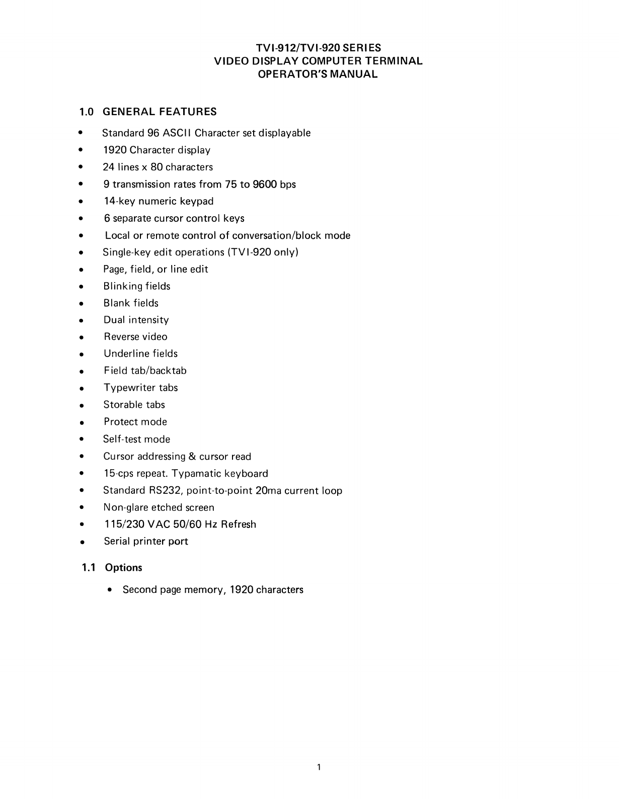
1.0 GENERAL FEATURES
•Standard 96 ASCII Character set displayable
•1920 Character display
•24 lines x
80
characters
• 9 transmission rates
from
75
to
9600
bps
•14-key numeric keypad
• 6 separate cursor
control
keys
•Local
or
remote
control
of
conversation/block mode
•Single-key
edit
operations
(TVI-920
only)
•
Page,
field,
or
line
edit
•
Blinking
fields
•Blank fields
•Dual
intensity
•Reverse video
•Underline fields
•Field tab/backtab
•
Typewriter
tabs
•Storable tabs
•Protect mode
•Self-test mode
•Cursor addressing &cursor read
•15-cps repeat.
Typamatic
keyboard
•Standard RS232,
point-to-point
20ma
current
loop
•Non-glare etched screen
•
115/230
VAC
50/60
Hz Refresh
•Serial
printer
port
1.1
Options
•Second
page
memory,
1920
characters

2.0
GENERAL
DESCRIPTION
The TeleVideo
TVI-912/TVI-920
terminals
are
compact smart terminals.
They
are
the result
of
state-of-
the-art design improvements which
allow
them
to
offer
high level performance at
extremely
low
cost.
The
TV
1-912/TV1-920 terminals
are
compatible
with
most computers.
Standard features include editing capability, protected field, addressable cursor, micro-processor con-
trol,
line and character insert/delete, upper and lower
case
characters and tabbing. Switchabletransmis-
sion rates ranging
from
75
to
9,600
baud are standard. Also included
as
standard
is
abuffered serial
printer
port.
A 1,920-character second
page
display
memory
is
optional
on all models.
3.0 SPECIFICATIONS
3.1
Monitor
Size: 12 inches (diagonally measured)
Phosphor: P4, non-glare read-out
3.2 Displayed Character Set
96-character ASCII upper and lower
case
alphabet
Number
of
lines: 24
Characters per line:
80
Screen capacity: 1,920
Dual intensity
Blinking
fields
Secure fields (non-display)
Inverse video
Underlined fields
3.3 Character
Font
7 x 10
dot
matrix
with
12 x
10
resolution
3.4 Key Board Format
3.5 Editing Features
Clear screen
to
space
or
null
Typeover
Character insert and character delete
Line insert and line delete
Absolute cursor addressing
Erase
to
end
of
page
Erase
to
end
of
line
or
field
Line
edit
3.6 Cursor Controls
~,~,
t,
t,
New
line, Home, Tab, Back Tab
2

3.7
Formatting Features
Tab
Back tab
Column tab
set
Blinking field
Inverse video
Underline
Dual intensity
Protected field
3.8
Parity
Even, Odd, Mark, Space
or
No
Parity.
3.9
Repeat
15-cps auto-repeat
3.10
Transmission
Conversation mode: Full
or
half
duplex
Block mode: Formatted
information
transmitted
by
line
or
page,
protected and unpro-
tected data,
or
unprotected data only.
3.11 Interfaces
Standard RS232
point-to-point
20ma current loop
RS232
to
printer
port
3.12
Data Rates
9
speeds:
75, 110,
150,300,600,
1200,2400,4800,9600
3.13
Dimension
Height:
Width:
Depth:
3.14
Weight
301bs.
13-1/4"
16-1/8"
20-1/16"
13.95 kg
33.66 cm
40.96 cm
50.96 cm
3.15
Operating Environment
Ambient
temperature
range
(non-condensing):
O°C
to
50°C (32°F
to
122°F)
Maximum relative
humidity:
95%.
3.16
Power Requirements
115 VAC
at
0.5
amps/230
VAC
at
0.25 amps,
50/60
Hz, 55W
3

4.0
INTERCONNECTION
4.1
Interconnection
Steps
Step 1:
Step 2:
Making sure the power switch on the terminal
is
turned
OF F, plug the terminal power
cord
into
grounded
outlet.
Connect the cable
from
the remote
computer
or modem
to
the interface connector (P3).
4.2
Main Interface Connector
(E
IA
RS232C Connector Pin/Signal List)
Pin No. Signal Name Bell System Code
1Frame Ground
AA
2Transmit Data
Output
BA
3Receive Data
Input
BB
4Request
to
Send
Output
CA
5Clear
to
Send
Input
CB
6Data Set Ready (opt.)
Input
7Signal Ground
AB
8Carrier Detect
Input
20
Data Terminal Ready
Output
CD
25 Current Loop +
13 Current Loop -
Transmit*
12
Cu
rrent Loop +
24
Cu
rrent Loop -Receive*
*Internal
Strap Options
for
Active/Passive.
(See
page
25
"Jumper
Options").
4.3 Printer Interface
Pin No. Signal Name
1Frame
Ground
3Serial Data (RS232)
4Printer Ready (Jumper Select)
6Terminal Ready
7Signal Ground
8Terminal
Ready
(Jumper Select)
20
Printer Ready
4

5.0
INSTALLATION
5.1
Local Installation
The
TVI-912/TVI-920
with
astandard communications interface (RS232)
can
be
cabled
directly
to
alocal computer.
5.2 Remote Installation
The
TVI-912/920
can
communicate
with
remote computers using amodem connected between
the
TVI-912/920
and the
communication
lines.
5.3 Terminal TURN-ON Procedure
Step
1.
Step
2.
Step 3.
Step 4.
Step 5.
First make sure
that
ON/OFF
switch at the rear
of
the terminal
is
in
OFF
position.
Plug the terminal cord
into
agrounded
115VAC
outlet.
Set the
ON/OFF
switch
to
ON
position;
the beep
will
sound.
Cursor
will
appear
at
its home position in
approximately
20 seconds.
If
the cursor does
not
appear
at
the
"home"
position, press HOME key.
If
the cursor
still does
not
appear, check
if
the brightness
control
is
properly
adjusted.
5
6.0
FUNCTIONAL
DESCRIPTION OF
TVI-912/TVI-920
6.1
Keyboard
The
TVI-912B
has
a
84
key keyboard comprised
of
alphanumeric characters, symbols and
control
keys
to
perform
its
full
operation.
The
TVI-920B
has
a103 key keyboard
which
adds
11
special
function
keys, six editing keys, and
two
transmission keys.
The
TVI-912C
has
a
82
key keyboard, in astandard
typewriter
style,
with
alphanumericcharacters,
symbols, and
control
keys.
The
TVI-920C
has
a
101
key keyboard, in astandard
typewriter
style,
that
adds
11
special func-
tion
keys, six editing keys and
two
transmission keys.
6.2 Contrast Control
The brightness
of
displayed data on the screen
can
be
adjusted
by
means
of
a
control
knob
on the
rear
of
the
TVI-912/TVI-920.
6.3 Transmission
Rates
The
TVI-912/TVI-920
meets the standard transmission rates
of
computer
interfaces, telephone
data lines, and modems
with
9speeds: 75, 110,
150,300,600,
1200,2400,4800
or
9600
baud.
Speed
is
selected
by
means
of
switches on the rear
of
the terminal.
6.4 Mode Selection
The
TVI-912B/TVI-920B
selects
Block
Mode
with
CTRL/ESC. The
TVI-912C/TVI-920C
selects
Conversation or
Block
Mode
by
operation
of
the Block/Conversation key in
conjunction
with
the
IIControl"
or
IISh
ift"
key.
6.4.1 Conversation Mode
Half
Duplex: In
Half
Duplex mode, the
TVI-912/TVI-920
sends
and receives data in
only
one
direction
at atime. Characters
are
displayed on the screen and transmitted
to
the
computer
at the
same
time
as
they
are typed
from
the keyboard.
TVI-912/TVI-920
receives and displays data simultaneously.
Full Duplex: In Full Duplex,
TVI-912/TVI-920
sends
and receives data in
both
direc-
tions simultaneously. Characters are transmitted
as
they
are
typed,
but
they
are
not
displayed. The typed characters
are
echoed
from
the
computer
back
to
the terminal,
then
they
are displayed on the screen.
6.4.2
Block
Mode
In Block Mode,
TVI-912/TVI-920
sends
and receives data in complete blocks. Data up
to
afu
II
screen can
be
entered
by
operator. In
th
is
mode, characters
are
stored and dis-
played
but
not
transmitted
until
aspecial code sequence
is
received
by
the terminal,
or
by
the depression
of
a
"send"
key on the
TVI-920.
The edited data
can
be
transmitted
partially
or
completely. This mode
is
utilized
for
fast transmission
of
large blocks
of
data.
6.5 Protect Mode
In Protect mode, those character positions designated
as
protected (lower
intensity)
cannot
be
modified.
The cursor cannot enter aprotected field. The cursor
will
be
advanced across the pro-
tected
field
to
the
next
unprotected position. The cursor may
be
back-spaced across aprotected
field.
(All
protected characters
are
identified
by
half
intensity.)
6
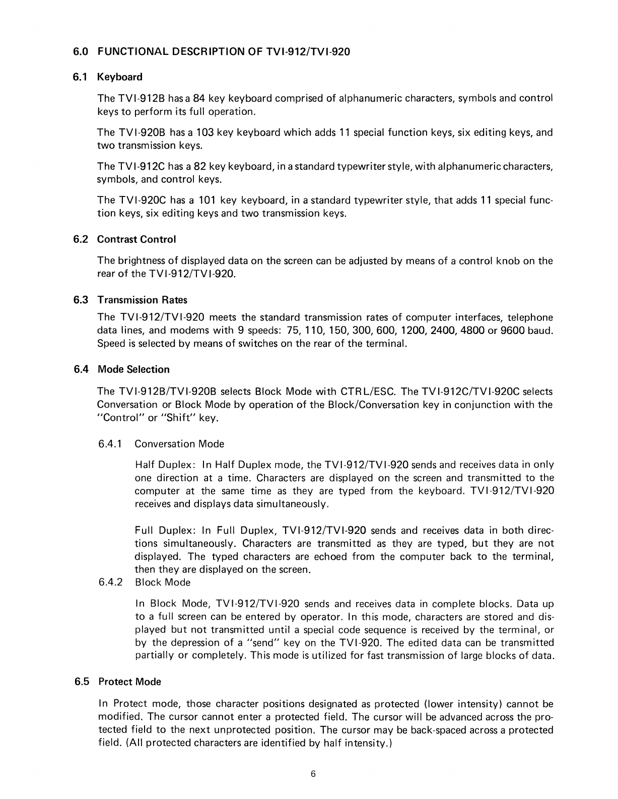
6.6 The Cursor
The cursor
of
TV
1-912/TV1-920
is
areverse video block, rectangular-shaped marker on the screen
which
indicates the
entry
spot
for
the
following
character
to
be
typed. When
typing,
the cursor
moves
from
left
to
right.
If
the cursor
is
placed over acharacter already displayed, the character
is
changed
into
areverse image inside
the
cursor. The cursor can
be
moved up,
down,
left,
right
or
home
by
pressing acursor
motion
key.
Any
desired cursor position in the display
area
can
be
obtained using
an
absolute cursor address
of
Y
(Iine-)
and X(column)
combination.
6.7 Editing Functions
Clear screen
to
spaces
or
nulls
Character typeover
Clear unprotected positions
Character insert and character delete
Line insert,and line delete
Erase
to
end
of
line
or
field
with
spaces
or
nulls
Erase
to
end
of
page
with
spaces
or
nulls
6.8 Formatting Capabilities
Tabs: When in
protect
mode, the tabs,
forward
and back, are set using columns
of
protected characters. The
TV
1-912/TV1-920 also offers
typewriter-sty
Ie
tab
when
not
in Protect mode. Up
to
80
tab positions may
be
set
without
loss
of
character location.
Field Reverse: The data
can
be
displayed
as
black characters on a
white
background.
Field
Blinking:
Blinking
fields
can
be
designated over
areas
of
the display and the designated
areas
blink
on and
off,
at
a 2 Hertz rate.
Field Blanking: Blank fields
can
be
designated over
areas
of
the display. The
areas
are blanked,
although the characters are still entered
into
display
memory,
i.e.,
can
be
used
to
enter code names, etc.
Field Protection: Protected fields can also
be
designated. The protected fields appear at areduc-
ed
instensity and, once designated
as
protected fields, cannot
be
over-written
unless the
TVI-912/TVI-920
is
removed
from
Protect mode.
7.0 OPERATION OF
TVI-912/TVI-920
7.1 Keyboard Function
The
TVI
912/TVI-920
keyboard contains alphanumeric keys
to
enter data, and
function
keys
(control
keys)
for
controll
ing operation.
For
all the
definitions
of
keyboards and
control
codes,
please refer
to
Quick
Reference Guide
(page
31).
Control
Keys and Functional Description
as
follows:
7
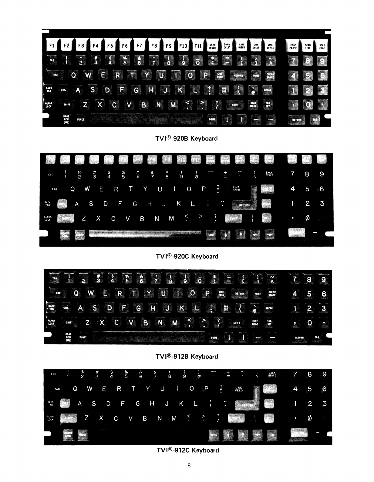
TV
I®-920B Keyboard
TVI®-920C Keyboard
TVI®-912B Keyboard
TVI®-912C Keyboard
8

7.1.1
Control
Keys-
Functional Description
Control
Keys Functional Description
CLEAR
SP
(ALL)
Performs alocal clear
space
when depressed. Transmits a
CTR LIZ when depressed
with
shift
in Conversation Mode.
If
in
Half
Duplex,
will
also clear screen
to
spaces
along
with
transmitting. CTR LIZ when received
by
the terminal, per-
forms
aclear unprotected
to
spaces.
CHAR
INSERT
(920) Moves character in the cursor
position
and all succeeding
ESC
Q
(ALL)
characters
to
the right by one position. If no protected field
is
encountered between the cursor and the end
of
the line,
this operation terminates at the end
of
the line and the last
character in the line
is
lost.
If
aprotected field
is
encountered,
and Protect Mode
is
on, the operation
will
terminate at the
end
of
the unprotected field
at
which the cursor rests, and
the last character in
that
field
is
lost.
CHAR
DELETE
(920) Deletes character in cursor position.
If
no
part
of
the line
is
ESCW
(ALL)
protected, characters
following
the cursor are moved
to
the
left.
If
the line
has
aprotected field,
only
the characters
from
the cursor
to
the protected field are moved
to
the
left.
This
operation terminates at the end
of
the line,
if
no protected
fields are on the line.
LINE
INSERT
(920) Inserts aline
of
nulls between the line above the cursor and
ESC
E
(ALL)
the line where the cursor
is
positioned.
At
this time, the line
where the cursor
was
located and all
following
lines move one
line downwards. The
cu
rsor
is
positioned at the start
of
the
new line. The
bottom
line
of
the screen
is
lost.
If
in Protect
mode, no operation
is
performed.
LINE
DELETE
(920) Deletes completely the line where the cursor
is
located.
All
ESC
R
(ALL)
following
lines move one line upwards. Cursor
is
positioned
at the start
of
the line.
If
in Protect mode, no operation
is
performed.
LINE
ERASE (920)
Erases
all character positions
from
cursor
to
the end
of
the
ESC
T,
(ESC
t)
(ALL)
line where the cursor
is
located and replaces
with
Space
Codes (ESC T)
or
Null
Codes (ESC t)
if
shifted
(TVI-920
only).
If
in protected mode, the operation
will
end at the
first
protected location
to
the
right
of
the cursor.
PAGE ERASE (920)
Erases
all character positions
from
cursor through end
of
dis-
ESC
Y,
(ESC y)
(ALL)
play and replaces
with
Space Codes (ESC
V),
or
Null
Codes
(ESC y)
if
shifted
(TVI-920
only).
If
Write Protect
is
on, pro-
tected
spaces
or
nulls
will
be
written.
(Note
that
if
the entire
page
is
protected in Protect Mode, the cursor
will
stop in the
Home position and no
further
character may
be
entered
until
an
unprotected area
is
made available,
or
Protect Mode
is
turned
off.)
CTRL
(ALL)
Modifies the code transmitted
by
pressing another key.
9

ESC
(ALL)
This key generates the standard ASCII
ESC
(I
BH). Receipt
of
this code
causes
the
following
character
to
be
interpreted
as
a
Function
command. This key does
not
repeat.
RUBOUT
DEL
(912B,920B)
This key
is
effective
only
in Conversation Mode.
Computer
(912C,920C)
normally
interprets
'/RUBOUT"
as
acharacter
erase
code.
BREAK
TAB
CTRL/I
BACKTAB
ESCI
HOME
CTRL/I\
PAGE
NEWLINE
CTRL/-
(ALL)
(ALL)
(ALL)
(ALL)
(ALL)
(ALL)
912B,920B
(ALL)
Transmits the
TTY
break signal.
In Protect Mode,
TAB
key moves the cursor
forward
to
the
first
unprotected character
following
aprotected field.
If
there
is
no
following
unprotected character, the cursor moves
to
the
Ilhome"
position. If
not
in Protect Mode, the cursor
is
moved
to
the
next
column
Tab location.
If
no
more Tabs
are set,
the
cursor does
not
move. (Transmits
CT
R
L/I.)
In PROTECT MODE,
IIBACK
TAB"
key moves cursor back-
wards
to
the
first
character position
of
its field.
If
cursor
is
at the
first
character position
of
its field,
it
moves
to
the
first
character position
of
the previous field.
If
cursor moves
through
Ilhome",
it
comes
to
rest at the last unprotected
position on the screen. In conversation mode, no action
is
taken. (Does
not
transmit
code.)
Moves cursor
to
the
first
character position
of
the
top
line
of
the display.
If
the
Ilhome"
position
is
protected, cursor
moves
to
the
first
unprotected position
following
(if
Protect
Mode
is
set). Transmits ASCII
RS
code
(IEH).
Moves the cursor
to
the
first
character position
of
the
next
line.
If
that
position
is
protected, cursor moves
to
the
first
unprotected position (Transmits
CTRL/_.)
SHIFT/PAGE
NEWLINE
ESC
K
t
,CTRL/K
~
,CTR L/J
~,CTRL/H
BACKSPACE
--+
,CTR
L/L
(912B,920B)
Displays alternate
page.
Cursor does
not
move. (Shift/Page-
Newline does
not
transmit
acode.)
(ALL)
(ALL)
tThis key moves cursor
to
he
next
higher line.
(ALL)
~
This key moves cursor
to
the
next
lower line.
(ALL)
~
This key moves cursor
to
next
position
to
its
left.
(912C, 920C)
(ALL)
--+
This key moves cursor
to
the
next
position
to
its right.
For all
of
the above keys, the cursor
will
advance
forward
to
the
next
unprotected position
if
the character
space
to
be
moved
to
is
protected and Protect Mode
is
on. (Transmits
corresponding
control
code.)
10

TA8SET
ESC
1
(9128,9208)
If
in Protect Mode, writes vertical
column
of
protected
spaces
(ALL)
in the column containing the cursor. Column begins in
row
containing the cursor and extends through
bottom
row.
If
not
in Protect Mode, a
typewriter
T
AS
is
set. Will
not
change
any protected characters.
SEND LINE
ESC4
SHIFT/SEND
LINE
ESC
6
SEND PAGE
ESC 5
(920)
(ALL)
(920)
(ALL)
(920)
(ALL)
"ESC
4"
or SEND LINE key causes unprotected characters
(EXCEPT
NULLS) in the displayed line containing the cursor to
be
transmitted, if in Protect Mode.
All
characteristics are transmitted
beginning atthe startof
the
unprotectedfield uptothe position
the
cursor
was
in
when
SEND
LINE
was
requested.
"ESC
6"
key causes all characters (EXCEPT NULLS) in
the
displayed
line
containing
the
cursor
to
be
transmitted.
All
char-
acters are
transmitted
beginning
at
the
start
of
the
lineup
tothe
position
the
cursor
was
in
when
SEND LINE
was
requested.
"ESC
5"
or SEND
PAGE
key causes unprotected characters
(EXCEPT
NULLS) of
the
displayed page to be transmitted.
All
characteristics are transmitted from
the
beginning of
the
first
unprotected field up to
the
cursor position
when
SEND
PAGE
was
requested.
SHIFT/SEND
PAGE (920)
ESC
7(ALL) "ESC
7"
causes all
characters
(EXCEPT NULLS) in
the
displayed
page
to
be
transmitted.
All
characters are
transmitted
from
the
beginning
of
the
page up
to
the
cursor
position
when
SEND
PAGE
was
requested.
PRINT
ESC
P
(9128,9208)
(ALL)
Enables
output
to
the hard
copy
printer,
which
is
optional.
PRINT
key pressed
causes
each
line
to
be
transmitted
to
the
printer,
followed
by
aCR,
LF,
NUL
sequence,
from
the
be-
ginning
of
the
page
to
the cursor position. The last character
will
be
followed
by
CR,
LF,
NUL.
If
in Protect Mode, the
protected (half intensity) character
will
be
replaced
by
spaces
(used
with
pre-printed forms).
LINE
FEED
(ALL)
CTRL/J
(ALL)
RETURN
(ALL)
CTRL/M
(ALL)
ENTER
(912C, 920C)
SHIFT
(ALL)
ALPHA
LOCK
(ALL)
This key moves cursor
to
the
next
lower line.
If
new position
is
protected, cursor skips
forward
to
the
first
unprotected
position.
Moves cursor
to
the
first
character position in the line which
it
rests,
or
to
the
first
unprotected position
of
the line
if
in
PROTECT MODE.
Selects upper character indicated on another key. This key
is
also
used
to
change operation
of
special keys.
Locks upper
case
for
alpha characters
only.
Does
not
affect
numeric
or
special keys.
11
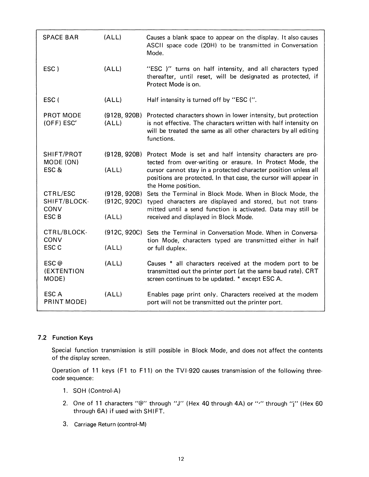
SPACE
BAR
ESC)
ESC
(
(ALL)
(ALL)
(ALL)
Causes
ablank
space
to
appear on the display.
It
also
causes
ASCII
space
code (20H)
to
be
transmitted in Conversation
Mode.
"ESC
)"
turns on
half
intensity, and all characters typed
thereafter,
until
reset,
will
be
designated
as
protected,
if
Protect Mode
is
on.
Half
intensity
is
turned
off
by IIESC (II.
PROT MODE
(OFF) ESC'
SHIFT/PROT
MODE (ON)
ESC
&
CTRL/ESC
SHIFT/BLOCK-
CONV
ESC
B
CTR
L/B
LOCK-
CONV
ESC
C
(912B, 920B) Protected characters shown in lower intensity,
but
protection
(ALL)
is
not
effective. The characters
written
with
half
intensity
on
will
be
treated the
same
as
all
other
characters
by
all editing
functions.
(912B,920B)
Protect Mode
is
set and
half
intensity
characters are pro-
tected
from
over-writing
or
erasure. In Protect Mode, the
(ALL)
cursor cannot stay in aprotected character position unless all
positions are protected. In
that
case,
the cursor
will
appear in
the Home position.
(912B,920B)
Sets
the Terminal in Block Mode. When in Block Mode, the
(912C,920C)
typed characters
are
displayed and stored,
but
not
trans-
mitted
until
a
send
function
is
activated. Data may still
be
(ALL)
received and displayed in Block Mode.
(912C, 920C)
Sets
the Terminal in Conversation Mode. When in Conversa-
tion
Mode, characters typed
are
transmitted either in
half
(ALL)
or
full
duplex.
ESC@
(EXTENTION
MODE)
ESCA
PRINT
MODE)
(ALL)
(ALL)
Causes
*all characters received
at
the modem
port
to
be
transmitted
out
the
printer
port
(at the
same
baud rate).
CRT
screen continues
to
be
updated. *except
ESC
A.
Enables
page
print
only.
Characters received at the modem
port
will
not
be
transmitted
out
the
printer
port.
7.2 Function Keys
Special
function
transmission
is
still possible in Block Mode, and does
not
affect
the contents
of
the display screen.
Operation
of
11
keys (F1
to
F11) on the
TV
1-920
causes
transmission
of
the
following
three-
code sequence:
1.
SOH (Control-A)
2.
One
of
11
characters II@" through
IIJ"
(Hex
40
through
4A)
or
","
through
Ilj"
(Hex
60
through
6A)
if
used
with
SHIFT.
3. Carriage Return (control-M)
12

2 =
9600
3=
4800
4=
2400
5=
1200
On the
TVI-912/TVI-920,
operation
of
the
IIFUNC"
key
with
another character key
will
cause
transmission
of
the
following
sequence:
1.
SOH
(Control-A)
2.
ASCII
Alphanumeric
code
for
character key pressed
3.
Carriage Return (control-M)
7.3 Numeric Key
Pad
The numeric key pad
has
keys
to
write
numerals
from
0
through
9, comma, period, ENTE
R,
and
-.
These keys
are
affected
by
SH
I
FT
just
as
the normal numeric keys.
7.4
ON/OFF
Switch
Th
is
ON/OF
Fswitch
is
located on the rear
of
the terminal. This
two-position
Switch controls AC
power
to
the terminal. Setting the switch
to
ON
position resets terminal circuits, positions cursor
at
"home",
and clears display memories
to
unprotected
spaces.
7.5
TVI-912/TVI-920
Controls
The
ON/OFF
and
other
manual controls
are
located on the rear
of
the terminal.
Contrast
Control:
Desired character brightness relative
to
screen background
can
be
selected
by
th
is
control>
Conversation Mode Switch:
Full
or
Half-Duplex Conversation Mode operation
can
be
selected
by
this switch and
it
is
located inside the terminal (accessable
from
the rear
of
the terminal).
Baud Rate Switch: This 10-position switch selects transmission rate at one
of
nine standard
speeds
from
75 baud
to
9600
baud.
(ONLY
ONE SWITCH
MAY
BE
DOWN
AT
A
TIME.)
6 =
600
7=
300
8=150
9=75
10=
110
7.6
Attribute
Codes
Setting
or
Resetting Visual
attribute
(Blink,
Blank, Reverse
or
Underline) always overrides any
previous Visual attributes set. Therefore,
to
add
an
attribute
to
any
that
already exist in the char-
acter locations beyond which the cursor rests, all the attributes desired must
be
started
at
that
point.
EXAMPLE
A
Assume a
full
screen
of
Reverse Video. You wish
to
have the
bottom
half
of
the screen Underlined and Reverse Video.
Position the cursor at line 11,
column
80.
Issue
to
the
TVI-912/TVI-920
ESC
j, then backspace
to
the
same
position and
issue
ESC
I.
The
bottom
half
of
the screen
only
is
now
Reverse
Video/Underlined.
13

To
eliminate any single
attribute
that
exists
with
others, the
attributes
that
are
to
remain must
be
set again, and then the undesirable
attribute
turned
off
with
the appropriate
ESC
Sequence.
EXAMPLE
B
Assume a
full
screen
of
only
Reverse Video. You
want
to
display a
Page
Heading
of
Underline Reverse
Video
in the center
of
the second line.
Position the cursor one
space
before where the new
attribute
is
to
be
set.
Issue
ESC
j(Start
Reverse
Video),
then backspace
to
the
same
position
and
issue
ESC
I.
The screen
will
now
be
Reverse
Video/Underline
from
that
point
to
the
bottom
of
the
page.
Now
position the cursor one
space
past the desired end
of
the Reverse Video, Underlined Field and
issue
ESC
j, backspace and
issue
ESC
m. The screen
will
now
be
Reverse Video
with
an
underline/Reverse
Video
Field on the second line.
To
display more than one Visual
attribute
over the
same
area, position the cursor one
space
prior
to
the location at which the attributes
are
to
be
displayed and
issue
the appropriate
ESC
sequence
for
the
first
attribute
to
be
set.
To
set the second
attribute,
positon the cursor over the
same
loca-
tion
used
to
set the
first
attribute
(or piggyback) and
issue
the
next
proper
ESC
sequence. Con-
tinue
this
until
all desired
attributes
are
set.
All
Visual
attributes
set (except
Half
Intensity-see
page 11)
will
be displayed
from
the
location
at
which
they
were
set,
to
the
end
of
the
page,
or
until
they
encounter
another
attribute
set
code. This
will
act as a
terminator
for
the
above
mentioned
attribute(s).
To
keep attributes
from
being erased in Protect mode, they should
be
set in Write Protect.
EXAMPLE
C
Assume
No
attribute
on screen and cursor in home position.
Issue
"Write
Protect
On"
code
(ESC)
)then
attribute
set code i.e.,
ESC
j
for
Reverse
Video. Then reset Write Protect (ESC ( ) and set Protect
mode (EXC
&)
or
"Shift
Prot"
on keyboard.
Now
depress
"Clear
Space"
key. The screen should still
be
in
Reverse
Video.
If
screen clears at no
attributes
at all, repeat above procedure.
If
Blink
or
Blank
is
on
with
Reverse Video, Underline,
or
both
and
it
is
to
be
turned
off,
Reverse
Video, Underline,
or
both
must
be
reset
at
the start
of
the
non-blinking/non-blanking
field
before
ESC
q
is
issued. When setting more than one
attribute
use
the
following
order: Reverse, Underline,
then
Blink.
14

When
Video
attributes
are
transmitted
to
the
computer
via the Send command,
or
to
the
printer
by
print
commands, the
following
bit
map indicates the codes
which
will
be
sent.
BIT
7654320
B3 B2
00
BLANK
01
NOT
ALLOWED
10
NORMAL
VIDEO
11
BLINK
B1
:
START
REVERSING
VIDEO
BO:
START
UNDERLINE
If
Bit
4
is
set, then B3, B2 indicate the start
of
anew
intensity
field;
otherwise, B3 and B2 have
no effect. Bits 0, 1indicate the start
or
end
of
reversing
or
underline field.
(1=START,
O=END).
7.7
Block
Mode/Conversation Mode
Message
Transmission
Send Line
Unprotected:
(ESC 4
or
SEND
LINE)
Cursor moves
to
the
first
character
position
of
the line.
All
following
unprotected
characters (ex-
cept
NULLS)
up
through
the previous cursor
position
are
transmitted,
followed
by
a
RETURN
code. Each
protected
field
is
indicated
by
an
FS
code.
Send
LineAl!:
(ESC60rSHIFT/SEND
LINE)
Cursor moves
to
the
first
character
position
of
the
line.
All
following
characters (except
NULLS),
protected
or
unprotected,
up
through
to
the previous cursor
position
are
transmitted,
followed
by
a R
ETU
RN code. Protected fields are bracketed
by
ESC)
and
ESC
(sequences.
Send
Page
Unprotected:
(ESC 5
or
SEND PAGE)
Cursor moves
to
'/home"
position.
All
unprotected
characters on the display (except
NULLS)
up
through
the previous cursor
position
are
transmitted,
followed
by aRETU
RN
code. Protected
fields
are
indicated
by
an
FS
code. The last character on aline
is
followed
by
a
US
code.
Send
Page
All:
(ESC 7
or
SHIFT/SEND
PAGE)
Cursor moves
to
Jlhome" position.
All
characters except
NULLS
up
through
the previous posi-
tion
are
transmitted,
followed
by
aRETU
RN
code. Protected fields are bracketed
by
ESC)
and
ESC
(sequences. The last character on aline
is
followed
by
a
US
code.
7.8 Conversation Mode Transmission
Half-Duplex
(Conversation Mode rear panel mode switch
to
HALF
position)
Keyboard
input
causes
graphics and
control
codes
to
be
transmitted,
character by character, and
causes
characters
to
appear on the display. Operation
of
an
edit
or
command key
causes
specified action
to
occur
on
the
display
but
no
codes are transmitted.
Full-Duplex
(Conversation Mode, rear panel mode switch
to
FU
LL
position)
Keyboard
input
causes
graph
ics
and
control
codes
to
be
transm
itted,
character
by
character,
but
graphics are dis-
played
only
upon receipt
from
the remote computer. Operation
of
an
edit
or
command key
causes
specified action
to
occur on the display
but
no code
is
transmitted.
15

7.9 Self Test Mode
The Self Test Mode may
be
used
to
verify
proper operation
of
the video display
circuitry,
the
serial interfaces,
UART,
and
control
processor. The test consists
of
the transmission
of
the com-
plete displayable character set,
with
all attributes (e.g., inverse, underline,
protect)
exercised.
Terminal must
be
CONFIGURED
in RS-232-Levels, i.e., S5-6 Down and S5-7 Up.
To
invoke the test,
perform
the
following
operation:
1.
Disconnect any interface connectors
to
other
devices (P3, P4).
2. Clear screen
of
all characters.
3. Connect a
jumper
between P3-2 and P3-3.
4.
Momentarily
short the
two
pins
next
to
the connector on the keyboard.
5. The display test pattern
will
be
generated. (Note
that
the display
will
update
only
after
100
characters have been transmitted -this may
be
asignificant delay at slower
BAUD
rates.)
6.
After
all test patterns have been displayed, the
BE
LL
will
sound.
7.
Verify
the test pattern
as
shown.
7.9.1
TV
1-912/TV1-920 Test Pattern
16
~Blinking
Line
This manual suits for next models
3
Table of contents
Other TeleVideo Desktop manuals

TeleVideo
TeleVideo TPC I SYSTEM User manual

TeleVideo
TeleVideo TS-1605 User manual

TeleVideo
TeleVideo 925 User manual

TeleVideo
TeleVideo TS 806H User manual

TeleVideo
TeleVideo 950 User manual

TeleVideo
TeleVideo TS 802H User manual

TeleVideo
TeleVideo 955 User manual

TeleVideo
TeleVideo 9320 User manual

TeleVideo
TeleVideo TS 806/20 User manual
Popular Desktop manuals by other brands


Lenovo
Lenovo IdeaCentre K315 hardware replacement guide

Fujitsu Siemens Computers
Fujitsu Siemens Computers CELSIUS R operating manual

Praim
Praim Neutrino Thin Client Series quick guide

Sony
Sony PCV-RS400C - Vaio Desktop Computer user guide

Advantech
Advantech ARK-2120 user manual

Lenovo
Lenovo ThinkStation P510 Hardware Maintenance Manual