TeleVideo TS 806/20 User manual
TeleVideo
TS
806/20
Computer
System
Installation
and
User's
Guide
~~:
~~
..
~~
~~~'I~IeVideo
Systems,
Inc.

TeleVideo
TS
806/20
Computer
System
Installation
and
User's
Guide
TeleVideo
Document
No.
2226500
October
1982
Copyright
(c)1982
by
TeleVideo
Systems,
Inc.
All
rights
reserved.
No
part
of
this
publication
may
be
reproduced,
transmitted,
transcribed,
stored
in
a
retrieval
system,
or
translated
into
any
language
or
computer
language,
in
any
form
or
by
any
means,
electronic,
mechanical,
magnetic,
optical,
chemical,
manual,
or
otherwise,
without
the
prior
written
permission
of
TeleVideo
Systems,
Inc.,
1170
Morse
Avenue,
Sunnyvale,
California
94086.
Disclaimer
TeleVideo
Systems,
Inc.
makes
no
representations
or
warranties
with
respect
to
this
manual.
Further,
TeleVideo
Systems,
Inc.
reserves
the
right
to
make
changes
in
the
specifications
of
the
product
described
within
this
manual
at
any
time
without
notice
and
without
obligation
of
TeleVideo
Systems,
Inc.
to
notify
any
person
of
such
revision
or
changes.
"Warning:
This
equipment
generates,
uses,
and
can
radiate
radio
frequency
energy,
and
if
not
installed
and
used
in
accordance
with
the
instruction
manual
may
cause
interference
to
radio
communications.
As
temporarily
per-
mitted
by
regulation,
it
has
not
been
tested
for
compliance
with
the
limits
for
Class
A
computing
devices
pursuant
to
Subpart
J
of
Part
15
of
FCC
Rules,
which
are
designed
to
provide
reasonable
protection
against
such
interfer-
ence.
Operation
of
this
equipment
in
a
residential
area
is
likely
to
cause
interference,
in
which
case
the
user
at
his
expense
will
be
required
to
correct
the
interference."
TeleVideoO
is
a
registered
trademark
of
TeleVideo
Systems,
Inc.
Z80A0
is
a
registered
trademark
of
ZILOG
Corporation.
CP/MO
is
a
registered
trademark
of
Digital
Research,
Inc.
RM/COBOLT"'
is
a
trademark
of
Ryan
-McFarland
Corp.
MmmOSTT"'
is
a
trademark
of
TeleVideo
Systems,
Inc.
TeleVideo
COBOLT"'
is
a
trademark
of
TeleVideo
Systems,
Inc.
WordStarT'"
is
a
trademark
of
MicroPro
International
Corporation.
TeleVideo
Systems,
Inc.
1170
Morse
Avenue
Sunnyvale,
California
94086
408/745-7760

TABLE
OF
CONTENTS
Page
LIST
OF
FIGURES
v
LIST
OF
TABLES
vi
1.
INTRODUCTION
1-1
1.1
System
Description
1-1
1.2
Limited
Warranty
1-1
1.3
Hardware
Configuration
1-3
1.4
Software
Overview
1-5
1.5
Using
the
Manual
1-6
2.
SYSTEM
INSTALLATION
2-1
2.1
Unpacking
2-1
2.2
Software
Registration
2-3
2.3
Selecting
the
Right
Location
2-3
2.4
Installation
2-4
2.5
Checklist
of
Installation
Instructions
2-10
3.
OPERATING
THE
SERVICE
PROCESSOR
3-1
3.1
Introduction
3-1
3.2
Initial
Start
Up
3-1
4.
OPERATING
THE
USER
STATIONS
4-1
4.1
Introduction
4-1
4.2
Turning
On
the
User
Station
4-1
4.3
Types
of
Drives
in
the
Multiuser
Environment
4-1
4.4
Booting
the
User
Station
4-3
4.5
Operating
Under
MmmOST
4-3
4.6
Working
with
MmmOST
4-6
5.
OPERATIONAL
GUIDELINES
5-1
5.1
Introduction
5-1
5.2
Floppy
Diskettes
5-1
5.3
Write
-Protecting
Diskettes
5-6
5.4
Backing
Up
the
Hard
Disk
5-7
5.5
Work
Habits
5-7
5.6
Summary
of
Good
Practices
5-8
6.
UTILITY
PROGRAMS
6-1
6.1
Introduction
6-1
6.2
Using
the
Utility
Programs
6-1
iii

TABLE
OF
CONTENTS
Page
7.
SYSTEM
TROUBLESHOOTING
AND
GENERAL
MAINTENANCE
7-1
7.1
Care
7-1
7.2
Troubleshooting
7-1
7.3
Changing
the
Exterior
Fuse
7-3
7.4
How
to
Get
Service
7-4
APPENDICES
A.
TS
806/20
Specifications
A-1
B.
Statement
of
Limited
Warranty
B-1
C.
Suggested
References
C-1
D.
Pin
Connector
Assignments
D-1
E.
Port
Asssignments
E-1
F.
Buying
Additional
Diskettes
F-1
G.
Cable
Specifications
G-1
H.
Using
the
Time
and
Date
Capability
in
Applications
Programs
H-1
INDEX
X-1
iv

LIST
OF
FIGURES
Page
1-1
TS
806/20
Computer
System
1-1
1-2
Possible
TS
806/20
Configurations
1-2
1-3
Floppy
Diskette
1-3
1-4
Diskette
Inside
Permanent
Plastic
Enclosure
1-4
2-1
Cable
Connector
2-5
2-2
Correctly
-Folded
Excess
Ribbon
Cable
2-6
2-3
Rear
Panel
of
the
TS
806/20
2-6
2-4
Location
of
Screws
in
the
TS
806/20
Case
2-7
2-5
Location
of
Internal
Switch
1
2-7
2-6
Closed
and
Open
Switches
2-8
3-1
On/Off
Switch
on
Rear
Panel
3-1
3-2
Location
of
Reset
Button
3-2
3-3
Service
Processor
Terminal
System
Message
3-6
5-1
Opening
Floppy
Drive
Door
5-1
5-2
Rerr~oving
Diskette
From
Jacket
5-2
5-3
Write
-Protecting
Diskette
5-2
5-4
Holding
Diskette
Before
Insertion
5-3
5-5
Inserting
Diskette
in
Floppy
Drive
5-3
5-6
Diskette
Tracks
and
Sectors
5-4
5-7
Diskette
and
Protective
Lining
Inside
the
Protective
Black
'lastic
Enclosure
5-5
5-8
Write
-Protected
Diskette
5-6
5-9
Typical
Back
-Up
System
5-7
7-1
Location
of
Exterior
Fuse
7-3
7-2
Good
Fuse
7-3
7-3
Burned
Out
Fuse
7-3
7-4
Location
of
Serial
Number
on
Rear
Panel
7-4
G-1
RS232C
G-1
G-2
RS422
G-1
LIST
OF
TABLES
Page
1-1
TS
806/20
Ports
1-5
2-1
Cable
Specifications
2-5
2-2
Switch
Settings
for
RS232
Terminal
Port
Switch
1
2-8
2-3
Setting
Baud
Rate
of
Terminal
Port
on
Switch
1
2-9
3-1
Hardware
Error
Abbreviations
3-6
4-1
TS
806/20
Logical
and
Physical
Drives
4-2
4-2
Logical
Drive
Capacities
4-2
6-1
Utility
Programs
Run
From
a
Service
Processor
Terminal
6-1
6-2
Utility
Program
Format
6-2
6-3
Utility Programs
6-2
6-4
COPYFI
LE
Error
Messages
6-6
7-1
Troubleshooting
Procedures
7-1
D-1
P2
Connector
Assignments
D-1
D-2
P7
Connector
Assignments
D-1
D-3
P4
Connector
Assignments
D-2
vi

1.
INTRODUCTION
1.1
SYSTEM
DESCRIPTION
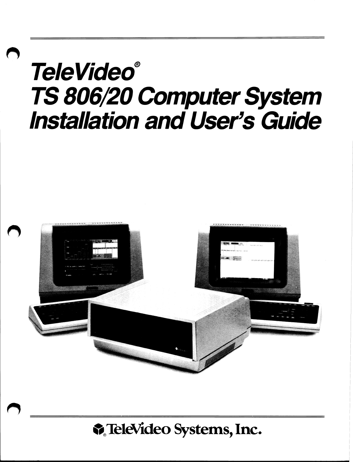
The
TeleVideo
TS
806/20
is
a
compact
tabletop
multiuser
microcomputer
which
can
support
up
to
six
user
stations.
A
Winchester
hard
disk
and
floppy
diskettes
provide
central
storage
of
data
for
all
users.
Figure
1-1
shows
the
TS
806/20
unit.
Many
combinations
of
peripheral
devices
can
be
attached
to
the
TS
806/20
serial
and
parallel
printers,
a
service
processor
terminal,
or
modem.
Figure
1-2
illustrates
several
of
the
possible
configurations.
Figure
1-1
TS
806/20
Computer
System
1.2
LIMITED
WARRANTY
The
TS
806/20
is
covered
by
a
limited
warranty.
The
terms
and
conditions
of
the
complete
limit-
ed
warranty
are
provided
in
Appendix
B.
Read
the
installation
instructions
completely
before
turning
on
your
system.
Incorrect
installa-
tion
may
void
the
warranty.
1-1

1
INTRODUCTION
~~r~r~r~M •~1
M
~~~~~~~~~~~~~~~1~~r~
1
~
~■
%
~■
■ ■
~■
~■
~
~~
~
~~
~~
~~
~~
~ ~ ~
~i
~i~i
i
~~
I►I~
rI~~I~
N
~~
~
1~M
~ ~~ ~
~~~
♦
~~i
~
i~~J^
^~~~
~~~rr~~~~
~r~~Tr~
Figure
1-2
Possible
TS
806/20
Configurations
1-2

1.
INTRODUCTION
1.3
1.3.1
1.3.2
1.3.3
HARDWARE
CONFIGURATION
Hardware
Overview
The
TS
806/20
is
a
tabletop
computer
which
contains
the
following
components:
One
51
/4
-inch
Winchester
hard
disk
drive
One
51
/4
-inch
floppy
disk
drive
Specification
details
are
given
in
Appendix
A.
The
TS
806/20
will
be
referred
to
as
the
service
processor.
Disk
Drives
The
TS
806/20
has
one
5
1
/4
-inch
Winchester
hard
disk
drive
and
one
5
1
/4
-inch
floppy
disk
drive.
The
floppy
disk
drive
is
located
on
the
left
side
of
the
computer.
(See
Figure
1-1.)
The
Winchester
disk
drive
is
located
immediately
to
the
right
of
the
floppy
disk
drive.
Hard
Disk
and
Floppy
Diskettes
The
hard
disk
is
permanently
sealed
in
an
air
-tight
enclosure
and
is
not
accessible
to
you.
It
has
a
capacity
of
19.14
megabytes
of
unformatted
disk
storage
(formatted
15.04
megabytes).
Data
can
be
stored
on
this
hard
disk
and
accessed
by
all
user
stations
connected
to
the
TS
806/20.
The
floppy
diskettes
are
5
1
/4
-inch,
double
-sided,
double
density
with
a
capacity
of
500
kilo-
bytes
of
unformatted
storage
(formatted
368.6
kilobytes).
Figure
1-3
shows
the
floppy
diskette.
Figure
1-3
Floppy
Diskette
Each
diskette
has a
magnetic
coating
on
both
sides,
much
like
a
phonograph
record.
Unlike
a
phonograph
record,
it
arrives
in
a
protective
black
plastic
cover
which
is
NOT
removable.
Lubri-
cants
inside
this
cover
increase
the
life
of
the
diskette.
The
actual
diskette
can
be
seen
through
some
of
the
slots
in
the
plastic
cover.
1-3

1.
INTRODUCTION
Figure
1-4
shows
the
actual
floppy
diskette
and
protective
lining
inside
the
plastic
cover.
When
cared
for
properly
(as
described
in
Chapter
5),
diskettes
can
be
used
many
times.
The
TS
806/20
can
use
any
floppy
diskette
which
meets
the
specifications
given
in
Appendix
F.
New
diskettes
must
be
formatted
before
data
can
be
stored
on
them
(as
explained
in
5.2.2).
Figure
1-4
Diskette
Inside
Permanent
Plastic
Enclosure
Applications
programs,
text,
data,
and
programs
which
operate
the
TS
806/20
can
be
stored
on
either
the
hard
disk
or
floppy
diskettes.
1.3.4
Peripheral
Devices
The
ports
on
the
rear
of
the
TS
806/20
allow
you
to
connect
a
wide
variety
of
peripheral
devices.
Up
to
six
user
stations
can
be
attached
to
the
TS
806/20.
These
user
stations
may
(but
do
not
need
to)
have
their
own
data
storage.
In
addition
to
the
user
stations,
a
service
processor
termi-
nal
is
used
to
run
utility
programs,
run
service
diagnostics,
modify
the
operating
parameters
of
MmmOST,
and
monitor
the
operation
of
the
TS
806/20.
A
user
station
can
also
operate
as
a
service
processor
terminal
by
changing
the
switch
setting
on
the
rear
panel.
Refer
to
the
opera-
tor's
manual
for
location
and
settings
of
the
switch.
Optional
peripheral
devices
can
be
shared
by
all
user
stations.
For
hardcopy
output,
you
can
connect
a
serial
printer
to
the
port
labeled
RS232
[OPT].
(This
could
be
a
dot
matrix,
line,
or
letter
-quality
printer.)
This
interface
is
compatible
with
most
RS232
-compatible
serial
printers
currently
available
on
the
market,
including
both
character
-by
-character
and
buffered
printers.
A
serial
device,
such
as
a
modem,
can
be
attached
to
the
RS232
[OPT]
port
instead
of
a
printer.
You
can
attach
a
parallel
Centronics
-type
printer
to
the
port
labeled
PRINTER.
Refer
to
Figure
1-2
where
several
possible
configurations
are
illustrated.
D
The
peripherals
described
here
are
all
in
addition
to
those
which
maybe
connected
directly
to
each
user
station.
1-4
1.
INTRODUCTION
Table
1-1
TS
806/20
Ports
Port
Description
TERMINAL
This
25
-pin
RS232
port
is
used
to
connect
a
service
processor
terminal.
This
port
is
used
for
running
system
utility
programs,
monitoring
the
TS
806/20
operation,
running
service
diagnostics,
and
modifying
the
MmmOST
parameters.
PRINTER
This
36
-pin
port
can
be
used
to
connect
a
parallel
Centronics
-type
printer.
RS232
[OPT]
This
25
-pin
port
is
used
to
connect
a
serial
printer
or
modem.
USER
1
Six
high-speed
serial
RS422
ports
are
available
to
connect
the
TS
806/20
to
user
stations
through
(any
TeleVideo
8-
or
16
-bit
system).
USER
6
1.4
1.4.1
SOFTWARE
OVERVIEW
Operating
System
Every
computer
needs
instructions
in
order
to
operate;
these
instructions
are
supplied
by
a
group
of
programs
collectively
called
the
operating
system.
When
the
TS
806/20
is
turned
on,
its
operating
system
is
loaded
into
memory
from
the
hard
disk
and
then
into
the
memory
of
each
user
station
which
is
turned
on.
All
TeleVideo
computers
use
CP/M
(Control
Program
for
Microcomputers)
Operating
System
software,
developed
by
Digital
Research
.
D
If
you
are
not
already
familiar
with
CP/M,
TeleVideo
highly
recommends
that
you
refer
to
the
reference
books
listed
in
Appendix
C
and
become
familiar
with
the
basic
operation
of
the
CP/M
operating
system.
When
the
TS
806/20
is
used
in
a
multiuser
environment,
it
also
uses
a
special
program
called
MmmOST.
MmmOST
is
an
acronym
for
Multiuser,
multiprocessor,
multitasking
Operating
Sys-
tem
Technology.
MmmOST
controls
access
by
the
user
stations
to
the
files
and
programs
stored
in
the
TS
806/20.
1.4.2
Programming
Languages
User
stations
can
use
any
programming
language
which
will
run
under
CP/M.
Among
these
are
BASIC, ALGOL,
APL,
"C,"
COBOL,
CBASIC,
FORTH,
FORTRAN,
MBASIC,
PL/I,
and
RM/
COBOL.
When
these
languages
are
used
with
MmmOST,
modifications
which
are
described
in
the
MmmOST
Programmer's
Manual
allow
them
to
take
advantage
of
the
features
of
MmmC~ST.
In
addition,
TeleVideo
COBOL
allows
applications
programs
to
be
used
with
MmmOST
with
little
or
no
modification.
1-5

1.
INTRODUCTION
1.4.3
Applications
Programs
Applications
programs
are
commercially
available
for
a
wide
range
of
tasks,
from
accounting
to
security.
In
addition,
you
may
write
your
own
applications
programs
in
one
of
the
programming
languages
compatible
with
CP/M.
Applications
programs
are
normally
run
in
the
user
stations,
not
in
the
service
processor.
1.5
USING
THE
MANUAL
This
manual
will
show
you
how
to
successfully
install
and
use
your*
new
TS
806/20
regardless
of
your
past
experience
with
computers.
Every
attempt
has
been
made
to
present
all
of
the
infor-
mationyou
will
need
in
a
complete
and
easy
-to
-understand
format.
Refer
to
the
operator's
man-
ual
supplied
with
your
user
station
also.
Your
comments
about
the
manual
are
welcome.
To
facilitate
this,
we
have
provided
a
Reader
Comment
Card.
Please
take
a
moment
to
complete
and
return
the
card
after
you
have
installed
your
system.
1.5.1
Organization
The
manual
is
organized
in
the
sequence
you
will
need
the
information.
The
chapters
are
as
follows:
2
Installation:
How
to
unpack
and
install
the
TS
806/20
3
Operating
the
Service
Processor:
How
to
install
CP/M
and
MmmOST
and
operate
the
system
4
Operating
the
User
Stations:
How
to
operate
user
stations
in
a
multiuser
environment
5
Operational
Guidelines:
How
to
effectively
use
the
system
and
floppy
diskettes
6
Utility
Programs:
How
to
use
the
system
utility
programs
7
Maintenance
and
Troubleshooting:
How
to
care
for
the
TS
806/20
and
what
to
do
if
you
have
a
problem
In
the
Appendices
are
the
specifications,
limited
warranty,
suggested
references,
and
technical
information.
1.5.2
Special
Information
Notes
will
call
your
attention
to
information
which
is
of
special
importance.
These
categories
of
notes
are
used:
D
General
useful
information
Important
information
concerning
your
safety
or
possible
loss
of
data.
When
you
see
this,
STOP
and
read
the
note
before
proceeding!
1.5.3
Format
of
Control
Commands
Control
commands
will
be
shown
as
n
plus
the
control
character
(e.g.,
nC).
1.5.4
Carriage
Returns
When
you
should
press
the
RETURN
key
on
the
operator's
keyboard,
the
symbol
<CR>
for
CARRIAGE
RETURN
will
be
used.
(On
Televideo
terminals,
you
can
press
the
ENTER
key
in-
stead
of
the
RETURN
key.)
~-s

2.
SYSTEM
INSTALLATION
2.1
UNPACKING
2.1.1
How
to
Unpack
The
TS
806/20
was
double
-boxed
when
shipped.
Follow
the
instructions
shown
here
to
unpack
your
system.
D
The
unpacking
process
will
be
easier
if
two
people
unpack
the
TS
806/20.
DO
NOT
USE
LONG,
SHARP
OR
POINTED
OBJECTS
TO
OPEN
THE
INNER
BOX
AS
THEY
MIGHT
DAMAGE
THE
ENCLOSED
SYSTEM.
1.
After
opening
the
outer
box,
lift
the
inner
box
containing
the
TS
806/20.
Gently
place
on
floor.
3.
Gently
turn
this
box
on
its
side.
2.
Open
the
box
containing
the
TS
806/20.
There
are
two
plastic
foam
pieces
protecting
the
system.
4.
Holding
the
box
firmly,
gently
turn
it
upside
down.
Lift
the
box
off
the
TS
806/20.
2-1
2.
SYSTEM
INSTALLATION
5.
TS
806/20
enclosed
in
two
foam
pieces.
6.
Turn
the
TS
806/20
(with
foam
still
in
place)
on
its
side.
7.
Remove
the
top
foam
piece.
D
8.
Lift
the
TS
806/20
away
from
the
bottom
foam
piece
and
gently
place
the
TS
806/20
on
a
sturdy,
level
table.
Save
all
packing
ma
teria/s
and
the
cartons
in
case
you
need
to
ship
the
TS
806/20
in
the
future.
2.1.2
Checklist
of
Components
As
you
unpack,
check
to
make
sure
you
received
the
following
items:
1.
TS
806/20
2.
Envelope
containing
the
following
items:
a.
TS
806/20
Computer
System
Installation
and
User's
Guide
b.
MmmOST
Programmer's
Manual
and
software
license
agreement
and
card
c.
Digital
Research
CP/M
User
Manual
containing
software
license
agreement
and
card
d.
One
floppy
diskette
containing
CP/M
(installation
only)
and
one
floppy
diskette
con-
taining
MmmOST.
2-2
2.
SYSTEM
INSTALLATION
D
IF
ANY
ITEM
IS
MISSING,
CONTACT
YOUR
DEALER
OR
DISTRIBUTOR
BEFORE
PRO-
CEEDI
NG
WITH
THE
/
NS
TA
L
LA
TION.
2.1.3
Shipping
Damage
Check
for
shipping
damage
before
proceeding
with
the
installation.
If
the
system
case
appears
to
be
damaged,
contact
your
freight
carrier
immediately.
DO
NOT
PROCEED
WITH
THE
IN-
STALLATION
IF
YOU
BELIEVE
THERE
IS
ANY
SHIPPING
DAMAGE.
If
in
doubt,
contact
your
dealer
or
distributor
as
well
as
the
freight
carrier.
2.2
SOFTWARE
REGISTRATION
Inside
the
front
cover
of
the
CP/M
Manual
that
accompanies
the
system
are
the
CP/M
Software
License
and
License
Agreement
and
inside
the
MmmOST
manual
is
the
MmmOST
Software
License
Agreement.
Read
the
agreements
and
sign
them
before
opening
the
package
contain-
ing
the
floppy
diskettes.
Signing
the
agreements
and
returning
the
cards
will:
1.
Entitle
you
to
use
the
CP/M
operating
system
and
the
MmmOST
operating
technology
on
your
TS
806/20
and
make
back-up
copies
for
your
own
use
2.
Register
you
as
a
CP/M
and
MmmOST
Owner,
allowing
you
to
receive:
a.
CP/M
User's
Newsletter
b.
Notices
of
updates
and
enhancements
to
TeleVideo
and
Digital
Research
software
c.
TeleVideo
and
Digital
Research
software
bug
reports
and
patches
d.
Discounts
on
updated
versions
of
Digital
Research
software
D
TeleVideo
will
pro
vide
you
with
information
regarding
MmmOS
T
and
CP/M
updates.
Do
no
t
a
t-
tem
p
t
to
ins
tall
an
y
CP/M
updates
without
firs
t
con
tac
ting
TeleVideo.
2.3
2.3.1
SELECTING
THE
RIGHT
LOCATION
Power
Requirements
The
TS
806/20
requires
a
steady
supply
of
power:
115
VAC
60
Hertz
(domestic)
at
1.0
amps
or
230
VAC
50
Hertz
(international)
at
0.5
amps
D
Incorrect
or
fluctuating
line
voltages
can
cause
disk
error
or
damage
to
the
system.
If
you
have
any
doubt
about
the
line
voltages
at
your
location,
ask
your
dealer
to
check
out
your
facility
be-
fore
proceeding
with
installation.
2-3

2.
SYSTEM
INSTALLATION
2.3.2
Physical
Requirements
The
TS
806/20
and
user
stations
should
be
within
300
feet
of
each
other.
The
service
processor
terminal
should
be
within
50
feet
of
the
TS
806/20.
A
serial
printer
should
be
within
50
feet
of
the
TS
806/20.
The
parallel
printer
(Centronics
-type)
should
be
within
10
feet
of
the
TS
806/20.
Refer
to
the
printer
instructions
for
recommended
distance.
Leave
at
least
four
inches
of
free
space
around
the
enclosure
for
proper
air
flow.
Place
the
TS
806/20
on
a
sturdy,
flat,
level
surface.
The
dimensions
are
given
in
the
specifications
in
Appendix
A.
2.3.3
General
Environment
2.3.4
The
TS
806/20
will
operate
best
at
temperatures
and
humidity
levels
in
which
you
are
also
com-
fortable.
Sudden
and
drastic
temperature
changes
may
adversely
affect
your
stored
data.
The
system
requires
a
clean
environment
free
of
contaminants
such
as
dust,
carpet
fuzz,
and
smoke.
Excessive
moisture
or
oil
particles
in
the
air
will
hinder
the
performance
of
the
system.
Keep
the
system
away
from
the
floor
where
dust
or
carpet
fuzz
would
be
more
likely
to
get
into
the
floppy
disk
drive.
Magnetic
Isolation
For
optimum
performance,
locate
the
system
at
least
five
feet
from
other
computing
equipment,
any
electrical
appliances,
or
equipment
(such
as
elevators,
radio
transmitters,
and
television
sets)
which
generates
magnetic
fields.
2.4
INSTALLATION
General
directions
for
all
installations
are
given
in
this
section.
The
next
four
subsections
give
directions
for
connecting
the
following
peripheral
devices:
1.
Up
to
six
user
stations
2.
A
service
processor
terminal
3.
A
serial
printer
or
modem
4.
A
parallel
Centronics
-type
printer
2.4.1
Cables
To
connect
the
TS
806/20
to
a
terminal,
user
station,
printer
and
any
other
peripheral
device
(such
as
a
modem),
you
will
need
cables.
The
quantity
and
types
of
cables
needed
are
deter-
mined
by
the
number
and
types
of
devices
to
be
attached.
Your
dealer
or
distributor
can
supply
you
with
the
appropriate
cables.
The
technical
specifications
for
each
type
of
cable
are
shown
in
Table
2-1.
Refer
to
Appendix
G
for
more
detailed
cable
specifications.
2-4

2.
SYSTEM
INSTALLATION
Table
2-1
Cable
Specifications
Distance
in
Feet
Between
TS
806/20
and
Peripherals
Type
of
Cable
1
to
20
20
to
100
Ribbon
cable*
24
gauge
twisted
pair
with
at
least
an
overall
shield
100
to
300
(maximum)
24
gauge
twisted
pair
(individually
and
overall
shielded)
*This
is
acceptable
as
long
as
the
ribbon
cable
is
not
placed
next
to
electrical
devices
or
cables
that
could
induce
electrical
interference
into
the
ribbon
cable.
Cable
connectors
commonly
have
D
-shaped
end
connectors
(Figure
2-1).
These
fit
onto
a
D
-shaped
pin
connector
on
the
rear
panel
of
the
system.
To
install
a
cable,
turn
the
connector
end
to
fit
the
pin
connector
on
the
device,
then
gently
but
firmly
push
on
the
connector.
Figure
2-1
Cable
Connector
As
you
connect
the
cables,
leave
some
slack.
If
you
have
excess
cable
left,
coil
it
loosely
and
secure
it
with
a
rubber
band.
Place
the
cable
out
of
the
way.
D
I
f
you
are
using
a
ribbon
cable,
do
no
t
roll
up
the
excess
cable.
Rolled
ribbon
cable
looks
nice
bu
t
it
creates
an
inductor
or
choke
which
can
adversely
affect
system
performance.
Excess
ribbon
cable
should
be
folded
accordion
-style
as
shown
in
Figure
2-2.
2-5
2.
SYSTEM
INSTALLATION
Figure
2-2
Correctly
-Folded
Excess
Ribbon
Cable
2.4.2
Power
Configuration
The
system
will
be
configured
for
your
power
requirements
at
the
factory
(either
115
or
230
VAC).
Athree-prong
plug
is
provided.
If
you
use
it
with
an
adapter,
ground
it
with
a
"pigtail."
The
power
cord
wires
are
color
-coded
as
follows:
Green
Earth
ground
Black
Primary
power
(hot)
White
Primary
power
return
(neutral)
2.4.3
Connecting
a
Service
Processor
Terminal
To
connect
a
service
processor
terminal
to
the
TS
806/20,
follow
these
steps:
1.
Attach
one
end
of
an
RS232
interface
cable
to
the
pin
connector
labeled
TERMINAL
on
the
rear
of
the
TS
806/20.
(See
Figure
2-3.)
2.
l~ttach
the
other
end
of
the
cable
to
the
RS232
pin
connector
on
the
rear
of
the
terminal.
(Refer
to
the
terminal
operator's
manual
if
necessary
to
locate
the
appropriate
connector.)
POWER
CORD
—•
~,
ON
~
~
~
~
OFF
POWER
FUSE
FA
N
WINCH
(DATA)
• •
WINCH
(CONTROL)
• •
PRINTER
Q~
>®
TERMINAL
RS232
(OPT)
p 0
O
O
USER
1
oQo
USER
7
O
O
O
USER
3
oVo
USER
4
OOO
USER
5
OOO
USER
6
OOO
Figure
2-3
Rear
Panel
of
the
TS
806/20
2-6
Table of contents
Other TeleVideo Desktop manuals

TeleVideo
TeleVideo 9320 User manual

TeleVideo
TeleVideo TVI-9128 User manual

TeleVideo
TeleVideo TS 802H User manual

TeleVideo
TeleVideo TPC I SYSTEM User manual

TeleVideo
TeleVideo 955 User manual

TeleVideo
TeleVideo 950 User manual

TeleVideo
TeleVideo 925 User manual

TeleVideo
TeleVideo TS-1605 User manual

TeleVideo
TeleVideo TS 806H User manual


