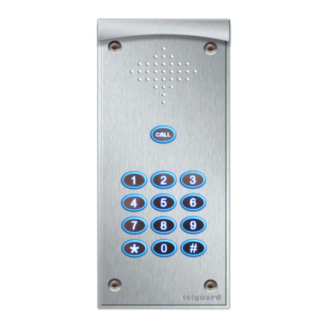
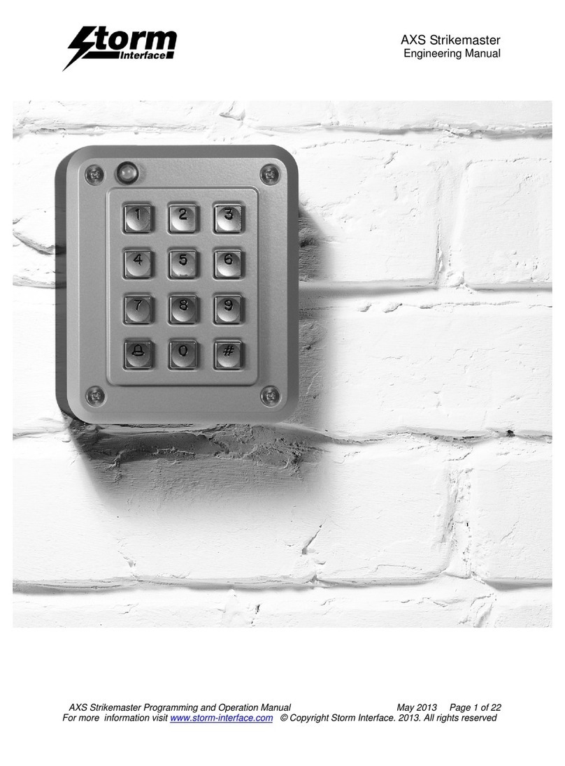
Telguard Hy-can Instruction manual

www.doorentry.co.uk
Page 1 of 7
...access to your home by the tone of your phone...
TM
Connections & programming
®

HY-CAN Connection Quick Start
When changing relay modules power off before
inserting. Ensure correct alignment.
Need help?
Call : 01306 710120
Polarity Check LED
* RED indicates +12v and 0v have been
crossed over.
* GREEN indicates polarity OK
0 V
External CAN bus to / from satellite panels
Wire HI to HI & LO to LO
Isolated input
*Use with volt free relay / switch
+12 V
External mic from satellite panels
Mic gain adjustment (not for satellite panels)
External speaker to satellite panels
12 V to satellite panels
‘OK’ LED
Green flashing indicates
normal operation
Relay SLOT 2
(empty)
Relay SLOT 1
(fitted)
To external equipment
www.doorentry.co.uk
1 of 2 internal CAN bus
Sockets,both wired in
parallel
Strike time adjustments
Page 2 of 7
...access to your home by the tone of your phone...
TM

Local Up & Down Speaker volume
Speaker connector
Modem bridge board
RJ11-4/6 telephone lead to PTSN
LED to show line looped for audio
LED to show line looped for modem
Serial number
www.doorentry.co.uk
Terminal emulator program required
Please refer to web site for software.
Page 3 of 7
Default relay codes for slot 1:
1# or # Pulse relay A 2# Pulse relay B 3# Latch relay A
4# Latch relay B 6# Unlatch relay A 7# Unlatch relay B
•Default relay times : Default set at 1 second (minimum).
Maximum 240 seconds
• Various relay modules can be fitted in slots 1 & 2. Any
adjustments in relay times can be done with the preset
adjustment on the module locally or later adjusted over the
Phone line.
•Default logins: Short menu ‘79’ followed by serial number.
Full menu ‘87’ followed by serial number.
Modem short menu ‘51’ followed by serial number.
Modem full menu ‘25’ followed by serial number.
• Unit is designed to work with CPA (called party answered)
enabled. BT provide this service free of charge and is obtained by
Phoning telguard on 01306 710120. The Unit can operate
without CPA Enabled but is not advised.
• The line connected to the telguard panel should be a single
dedicated line. All additional services ie: ring back prompt, call
minder must be removed. Dial ‘150’ for BT customer services/
Sales & billing for this to take place.
• Telguard Power supply units must be used and should not
power any other equipment.
PC Programming
-For more information on relays please refer to web site.
...access to your home by the tone of your phone...
TM
Dedicated programming
Connector for PC via AVIT USB lead

Need help?
Call : 01306 710120
1. Dial into door entry unit
2. Press default ‘79’ followed by serial number.
Voice assist *call point setup*
“
ENTER CALL POINT FOLLOWED BY ‘STAR’
ENTER NUMBER NOW
This allows access to the full menu. If you do
need to alter any elements of the system
that are not obtainable via the short menu
then it is recommended that you use a PC or
a modem to configure these features.
Terminates the session and hangs the line
up.
Useful Tips
If at any stage you would like the Robot to repeat the
last statement, press ‘HASH’ key when the Robot
has stopped talking. Robot will then say: “I said
The robot voice can be changed in the full menu. Levels
here can also be adjusted.
If you are at the Panel and require to set numbers,
you can switch between listening on the phone or
the panel. To activate this feature, key in: ‘1, 2, 3’
and ‘STAR’. Use this feature at the beginning of a
session where possible. To return to phone repeat
the above key in sequence.
ENTER NEW RINGING TIME NOW
ENTER ‘0’ THEN ‘STAR’ TO END SESSION
25.06.09 firmware Vxx.xx Page 4 of 7
Enter ‘1’ then ‘STAR’ to set telephone numbers
Enter ‘3’ then ‘STAR’ to log into full menu.
Enter ‘0’ then ‘STAR’ to exit configuration
...access to your home by the tone of your phone...
TM

1. Dial into door entry unit. Alternatively you can use the keypad locally.
2. Press default ‘87’ followed by the serial number to log into full menu.
• Enter 2 followed by *star
• Enter 2 followed by *star
• Enter your new pin, can be no more than 8 digits long including * or #
-wait six seconds after last key stroke .
• Enter ‘1’ followed by *star to edit relays (this is to assign your pin to a relay)
• Enter ‘1’ followed by *star to assign your pin to relay slot 1 or enter ‘2’ followed by *star to assign pin to relay slot 2.
• Enter ‘1’ followed by *star to pulse A (default 1 sec)
Enter ‘2’ followed by *star to Latch A
Enter ‘3’ followed by *star to Unlatch A
Enter ‘4’ followed by *star to Pulse B
Enter ‘5’ followed by *star to Latch B
Enter ‘6’ followed by *star to Unlatch B
* your pin and relay output is now saved*
•Enter ‘0’ followed by *star x3 times to return back to main menu.
-If you need to exit configuration enter ‘0’ followed by *star again-
• To Enter another pin repeat steps above from the main menu.
Your pin can consist of up to 8 digits including * & #.
after you have entered your pin please wait six seconds
after last key stroke for the pin to be saved.
Enter ‘2’ followed by
Enter ‘2’ followed by
Enter pin number you want to change, wait six seconds
Enter ‘3’ followed by
Enter ‘1’ followed by to confirm delete
For deep editing of parameters it is suggested you
use the AVIT USB lead & software provided with your
Telguard unit. This allows you to connect directly to
your unit via a PC (locally) or via modem (remotely).
Instructions and driver installation are also located on
the disc.
...access to your home by the tone of your phone...
TM
Page 5 of 7
Voice assist Full *Pin Entry setup*

Satellite panels
• Mounted to the rear of each Satellite panel
• Compatible with any telguard panel from the hy-can range
Satellite PCB
123
Multi Panel System
4
567
• Control up to seven Satellite panels
• Compatible with any telguard panel from the hy-can range
• Up to 300 M cable length between satellites & hub
System HUB
• HY-CAN PCB
• Complete With Metal Enclosure
• Will control up to 7 Satellite panels
1
Page 6 of 7
...access to your home by the tone of your phone...
TM

External CAN bus to/from
satellite panels Wire
HI to HI, LO to LO & 0 V to 0 V
External mic from satellite panels
12 V to satellite panels
External speaker to satellite panels
Page 7 of 7
Multi Panel System
Aux Input
Inputs for x8 buttons
Mic gain
adjustment
Relay Module (Dual Opto Shown) Speaker Connector
Expansion CAN
For displays, keypads
etc.
‘OK’ LED
Green flashing indicates
normal operation
• Connectors on satellite PCB can be daisy chained
to other satellite panels if required.
• If using Panels with heavy loads (ie displays, illuminated
Keypads etc) it is suggested you use an additional power
Supply at each satellite panel.
• Each satellite panel is numbered from 1 to 7. Please
ensure each system does not comprise of identical panel
Numbers.
Satellite PCB
PCB HUB
Mic Connector
...access to your home by the tone of your phone...
TM
Table of contents
Other Telguard Intercom System manuals

