Kanardia Nesis User manual

Nesis User’s Manual
Kanardia
September 2011
©
Kanardia d.o.o.
Nesis User Manual – Version 2.0
1

Nesis — User’s Manual
Contact Information
Publisher and producer:
Kanardia d.o.o.
Ulica heroja Rojˇska 70
SI-3000 Celje
Slovenia
Tel: +386 590 12 521
Fax: +386 590 11 416
Email: info@kanardia.eu
A lot of useful and recent information can be also found on the Internet. See http://www.
kanardia.eu for more details.
Copyright
This document is published under the Creative Commons, Attribution-ShareAlike 3.0 Un-
ported licence. Full license is available on http://creativecommons.org/licenses/by-sa/
3.0/legalcode web page and a bit more human readable summary is given on http:
//creativecommons.org/licenses/by-sa/3.0/. In short, the licens gives you right to copy,
reproduce and modify this document if:
you cite Aleˇs Krajnc, Kanardia d.o.o. as the author of the original work and
you distribute the resulting work only under the same or similar license to this one.
Credits
This document was written using TeTeX (L
A
T
E
X) based document creation system using
Kile integrated LaTeX environment running on Linux based operating system. Most of the
figures were drawn using Open Office Draw and Inkscape applications. Photos and scanned
material was processed using Gimp. All document sources are freely available on request
under the licence mentioned above and can be obtained by email. Please send requests to
info@kanardia.eu.
Revision History
The following table shows the revision history of this document.
Revision Date Description Document File
2.0 30 Sept 2011 Initial release NesisUserManual-200.pdf
2.0.1 15 March 2012 Minor update NesisUserManual-201.pdf
The documents can be downloaded from Kanardia web site www.kanardia.eu.
Version 2.0 2
©
Kanardia 2011

Nesis — User’s Manual CONTENTS
Contents
1 Introduction 6
1.1 General Information About Nesis . . . . . . . . . . . . . . . . . . . . . . . . . 6
1.2 Principles of the Operation . . . . . . . . . . . . . . . . . . . . . . . . . . . . 7
1.2.1 Attitude, Heading and Velocities . . . . . . . . . . . . . . . . . . . . . 7
1.2.2 EngineSensors ............................... 8
1.2.3 SensorCalibration ............................. 8
1.3 Charts, Flight and Navigation Information . . . . . . . . . . . . . . . . . . . . 9
2 Nesis Basics 10
2.1 CommandPanel .................................. 10
2.2 TurningOn/Off................................... 11
2.2.1 Start-upProcedure............................. 11
3 The Five Major Screens 13
3.1 Classic Flight Information – Screen 1 . . . . . . . . . . . . . . . . . . . . . . . 13
3.1.1 Menu .................................... 14
3.1.2 Moving Map Zoom Level . . . . . . . . . . . . . . . . . . . . . . . . . 15
3.2 Navigation–Screen2 ............................... 15
3.2.1 Menu .................................... 16
3.3 EngineMonitor–Screen3............................. 17
3.3.1 Menu .................................... 18
3.4 Modern Flight Information – Screen 4 . . . . . . . . . . . . . . . . . . . . . . 18
3.4.1 Menu .................................... 21
3.5 Settings–Screen5................................. 21
4 Flight-Time Activities 22
4.1 SettingQNH .................................... 22
4.1.1 QFEOperation............................... 22
4.1.2 InitialQNHSetting ............................ 22
4.2 List of Nearest Airports . . . . . . . . . . . . . . . . . . . . . . . . . . . . . . 23
4.3 SelectingaWaypoint................................ 24
4.3.1 The Waypoint Selection Mode . . . . . . . . . . . . . . . . . . . . . . 24
4.3.2 NameFilter................................. 25
4.3.3 RadiusFilter ................................ 25
4.3.4 TypeFilter ................................. 26
4.3.5 NewUserWaypoint ............................ 26
4.4 RouteSelection................................... 27
4.4.1 ActivatingaRoute............................. 27
4.4.2 RouteManipulation ............................ 27
4.5 AdjustingFuelLevel................................ 28
Version 2.0 3
©
Kanardia 2011

Nesis — User’s Manual CONTENTS
5 Browsig the Map 29
5.1 MovingtheMap .................................. 29
5.2 ZoomingtheMap.................................. 29
5.3 Waypoint ...................................... 30
5.4 Route ........................................ 30
5.5 DirectTo ...................................... 31
5.6 Home ........................................ 31
6 Settings 32
6.1 RoutePlanner ................................... 33
6.1.1 RouteListCommands........................... 34
6.1.2 Waypoint Editing Commands . . . . . . . . . . . . . . . . . . . . . . . 34
6.2 Logbook....................................... 35
6.3 UserPreferences .................................. 36
6.3.1 User..................................... 37
6.3.2 Map..................................... 37
6.3.3 System ................................... 37
6.4 Units......................................... 38
6.5 CompassCalibration................................ 38
6.5.1 FirstStep.................................. 39
6.5.2 SecondStep................................. 40
6.6 Time&Date .................................... 40
6.7 SoftwareUpdate .................................. 41
6.7.1 Downloading Updates . . . . . . . . . . . . . . . . . . . . . . . . . . . 41
6.7.2 Extracting Update Files into USB Stick . . . . . . . . . . . . . . . . . 41
6.7.3 Transferring Files into Nesis . . . . . . . . . . . . . . . . . . . . . . . . 42
6.7.4 FirmwareUpdate.............................. 43
6.8 FileTransferService ................................ 43
6.9 Alarms........................................ 44
6.10UserWaypoints................................... 44
6.11SystemPreferences................................. 45
6.11.1 Nesis..................................... 45
6.11.2 Glide .................................... 46
6.12AttitudeAdjustment................................ 46
6.12.1 YawMisalignment ............................. 46
6.12.2 Roll and Pitch Adjustment . . . . . . . . . . . . . . . . . . . . . . . . 46
6.13Airplane&Engine ................................. 47
6.13.1 EngineType ................................ 47
6.13.2 Daqu Parameter Table . . . . . . . . . . . . . . . . . . . . . . . . . . . 48
6.14TankCalibration .................................. 49
Version 2.0 4
©
Kanardia 2011

Nesis — User’s Manual CONTENTS
6.14.1 SetupTanks ................................ 50
6.14.2 Calibrate Sensors (Min/Max) . . . . . . . . . . . . . . . . . . . . . . . 50
6.14.3 EditTankShapes ............................. 51
6.15SensorOffsetCorrection.............................. 52
7 Instruments 53
7.1 AirspeedIndicator ................................. 53
7.2 AttitudeIndicator ................................. 54
7.3 AltitudeIndicator ................................. 55
7.4 Vertical Speed Indicator and Accelerometer . . . . . . . . . . . . . . . . . . . 55
7.5 Tachometer and Manifold Pressure Indicator . . . . . . . . . . . . . . . . . . 56
7.6 Gyrocopter Rotor and Engine RPM Indicator . . . . . . . . . . . . . . . . . . 57
7.7 Helicopter Rotor and Engine RPM Indicator . . . . . . . . . . . . . . . . . . 57
7.8 Heading Indicator with Moving Map . . . . . . . . . . . . . . . . . . . . . . . 58
7.9 MiniEngineMonitor................................ 59
7.10FuelComputerMonitor .............................. 60
Version 2.0 5
©
Kanardia 2011

Nesis — User’s Manual 1. Introduction
1 Introduction
First of all, we would like to thank you for purchasing our product. Nesis is a complex
instrument and we strongly recommend reading the manual before using Nesis. The intro-
duction chapter contains some general information about the instrument and principles of
the operation. Later chapters describe Nesis use and reveal the details.
You may be also interested in reading the Nesis Purchase Guide and Nesis Installation Manual
documents.
1.1 General Information About Nesis
Nesis consists of electronic units which work closely together to bring flight, engine and fuel
information onto graphical display. The system is presented on figure 1. The system consists
of the following electronic components:
Figure 1: Illustration of minimal Nesis configuration.
Engine monitoring unit (Daqu) is used to connect the engine, fuel and electric sensors.
Airu is an inertial navigation unit (AHRS) aided by the GPS and pressure sensors.
Airu provides attitude, position and velocities. Airu is hidden inside the Primary Nesis
display.
Mabu unit is a hidden unit and serves as motherboard for the embedded computer, as
a data logger and as a CAN bus interface. Mabu is integral part of any Nesis display.
Primary Nesis display presents all relevant information that appears on the CAN bus
in a pilot friendly form on a large LCD screen. Most of this manual describes how to
access, read and interact with the Nesis display.
The Nesis system can be easily extended into a much more complex form, figure 2. We
achieved this by introducing CAN bus for the communication between the units. The CAN
bus does the magic of the all possible known and unknown future extensions. Imagine the
CAN bus as a kind of computer network. Just like new computers can be easily connected
to the network, we connect new devices to CAN. This allows introduction of secondary Nesis
display, autopilot, weather service, external warning panel lights, transponder. . .
Version 2.0 6
©
Kanardia 2011

Nesis — User’s Manual 1.2 Principles of the Operation
Figure 2: Illustration of extended Nesis configuration using CAN bus.
Although the secondary Nesis display does not have the Airu unit inside, it is fully functional
and behaves almost exactly like the primary Nesis display.
The Nesis family of products and accessories keeps growing and growing. Please refer to the
Nesis Puchase Guide for all available options.
1.2 Principles of the Operation
As it was indicated above, Nesis uses special units to provide the information. The flight
information (attitude, position and velocities) are obtained by Airu and Magu, while all
engine related information is obtained from Daqu. All these units are connected to the CAN
bus.
1.2.1 Attitude, Heading and Velocities
Nesis uses state of the art MEMS1sensors to read various physical quantities. Since all
sensors are solid state, Nesis has no moving parts. This means it has less problems with
fatigue and ageing. The following MEMS sensors are used in the Nesis system:
The angular rate sensors, also known as gyros, are used in the attitude calculation.
The angular rates are integrated in time in order to predict new attitude from the old
one. We could say that they give short-time attitude prediction. They are also used in
gravity vector calculation.
The acceleration sensors are measuring apparent gravity vector. The true gravity vector
is calculated assuming coordinated flight and readings from the other sensors (veloc-
ity and angular rate sensors). The ball slip indicator is directly obtained from the
acceleration sensors.
The absolute pressure sensor is used to calculate altitude and vertical velocity (vario).
The differential pressure sensor provides indicated airspeed (IAS). When it is coupled
with the outside air temperature sensor, it also calculates true air speed (TAS).
1MEMS – micro-electromechanical systems, a.k.a micromachines, a.k.a micro systems technology.
Version 2.0 7
©
Kanardia 2011

Nesis — User’s Manual 1.2 Principles of the Operation
The magnetic field sensors are used to measure the magnetic field vector. This vector
is needed to determine the airplane magnetic and true heading. The later also needs
magnetic declination, which is automatically calculated from the world magnetic model2
when airplane position is known. Note that the magnetic field sensor is optional and
Nesis works well without it.
Assuming coordinated flight we calculate the referencing attitude from the gravity vector and
heading. These values are then compared with the short-term prediction of the attitude. Non-
linear Kalman filters are used to combine the short-term prediction and referencing attitude
solution into one most probable solution. This is what you see on the attitude indicator.
In a very similar way, short-term inertial position prediction is compared with the GPS
position. Again, Kalman filtering is used to obtain the final solution.
1.2.2 Engine Sensors
Engine related sensors are connected to the engine monitoring unit (Daqu). Daqu is designed
to be installed on the engine side of the firewall. This has two advantages:
Since the unit is close to the engine, all cables are short and no extensions are needed.
This means less weight and makes installation simpler, too.
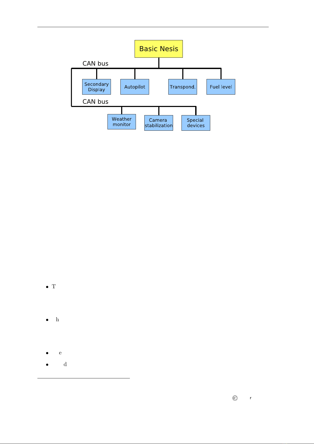
We need only one tiny hole trough the firewall for the CAN bus cable. The cable
transfers all the information and provides the power supply for Daqu.
Daqu is designed to monitor engine sensors for various engines up to six cylinders (e.g. Rotax,
Jabiru, Lycoming). When an engine is equipped with proper sensors, it can measure engine
RPM, cylinder head temperature (CHT), exhaust gas temperature (EGT), oil pressure, oil
temperature, fuel pressure, fuel flow, fuel level, manifold pressure, carburetor air temperatue,
voltage, battery current, alternator current, coolant temperature and more. In the case of
gyrocopter or helicopter installation, it also reads the rotor RPM sensor. The results of all
these measurements are then transmitted on the CAN bus, where all other units are able to
read them.
1.2.3 Sensor Calibration
Almost all MEMS sensors have one common problem – they are sensitive to the temperature
change. This means that each unit must be calibrated individually. Each sensor of every
unit is measured at different temperatures and compared with reference values. Results
are optimized mathematically in order to minimise the sensor errors. Resulting calibration
coefficients are written into flash memory of the microcontroller. This procedure can be done
in our lab only, since some special tools and machinery are needed.
The compass calibration, however, is an exception. Although the electronic compass (Magu)
is carefully calibrated in our lab, it needs to be recalibrated in your airplane. Practically every
airplane has some magnetic material present in the compass surroundings. Such material
locally disturbs Earth magnetic field and compass must take this disturbances into account.
Please refer to section 6.5 on page 38 for more details.
2The world magnetic model is maintained and updated by National Geophysic Data Center, http://www.
ngdc.noaa.gov/geomag/
Version 2.0 8
©
Kanardia 2011

Nesis — User’s Manual 1.3 Charts, Flight and Navigation Information
1.3 Charts, Flight and Navigation Information
Charts, flight and navigation information is obtained from many different sources. All these
sources are freely available on the Internet. Wherever it is possible we cross-check the infor-
mation and we try to make it current. However, this is not possible in all aspects and the
quality of the information may vary from country to country.
It is important to notice that we cannot guarantee that the information included
with Nesis or otherwise provided by Kanardia is current and correct. It is the
pilot responsibility to prepare himself for the flight and to collect all required
information from reliable sources. It is strongly suggested that the pilot keeps
valid printed navigation maps and other legally required material at disposal
anytime during the flight.
Version 2.0 9
©
Kanardia 2011

Nesis — User’s Manual 2. Nesis Basics
2 Nesis Basics
This chapter describes the organization of the Nesis instrument. It teaches you about the
individual buttons and their meaning. After reading you will be familiar with basic Nesis
operations. Forthcoming sections reveal the details.
2.1 Command Panel
The Nesis command panel is organized according to figure 3. It uses eight push buttons and
one rotating knob to manipulate the user interface. Additionally, it has an USB port3used
for software, chart and data updates.
Figure 3: Organization of Nesis front panel.
Here is a brief description of individual items:
The On/Off button is used to turn Nesis on/off.
The USB port (or SD card slot) is used for software, chart and data updates.
The OK/Menu button is used to confirm selection, to accept a decision or to display a
menu.
The rotating knob, hereinafter referred to as the knob, is mostly used to select things,
change values, change zoom levels, etc.
The Cancel/Esc button is used to reject selection, to cancel some decision or to
change/escape to some other selection level.
The multi-function buttons Btn 1 ...Btn 5 have two modes:
3Some earlier versions use SD card slot for the same purpose. In this case SD card also stores all map files
and it must be kept inserted during the flight.
Version 2.0 10
©
Kanardia 2011

Nesis — User’s Manual 2.2 Turning On/Off
1. Direct mode – with no menu labels shown on the display, the buttons allow direct
access to individual screens.
2. Menu mode – is active when at least one menu label is visible on the screen.
For the moment, try to remember the position of the OK/Menu and the Cancel/Esc buttons.
2.2 Turning On/Off
The On/Off button is used to turn Nesis on or off. It has no other meaning. The button
sends the signal to the electronic circuit. Depending on the current status of the electronics,
it executes one of the following actions.
If Nesis is off, a short press on the On/Off button turns it on.
If Nesis is on, a short press on the On/Off button starts the shutdown procedure. Any
action during the shutdown period cancels the operation.
A long press on the On/Off button for about 5 seconds unconditionally turns Nesis off
by cutting the power to the internal computer. In this case internal buffers are not
flushed and Nesis will take a little longer to boot on the next start. This procedure
should be used only for the cases when Nesis stops responding.
Note: The On/Off button is a soft button and the internal electronic circuit consumes a
small amount of electric energy even when Nesis is off. Although such consumption is very
small, it may influence the condition of your battery when the airplane is not used for a
very long period (say a few weeks). Therefore it is strongly recommended that Nesis is not
connected directly to the battery. It should be connected to an avionics power bus, which
has a mechanical switch between the bus and the battery.
2.2.1 Start-up Procedure
When Nesis is powered on, the start-up procedure commences. The internal computer starts
loading operating system and the Nesis main program. When the program is loaded, it
continues loading various databases like airfields, navigation points, airspaces, charts etc.
This procedure takes some time. Once the program is ready, it opens the start-up dialog as
shown on figure 4.
Figure 4: Initial agreement (left), pilot selection, QNH and fuel level setting (right).
Pressing the OK button accepts the agreement and advances to the next page. This page asks
for the pilot name, QNH and fuel level. Use the following commands to enter the required
information.
Version 2.0 11
©
Kanardia 2011

Nesis — User’s Manual 2.2 Turning On/Off
1. Turn the knob to select the pilot4. Press the OK button to confirm the pilot selection.
2. This takes you to fuel level selection5. Turn the knob to set current fuel level and press
the OK button. Act conservative and set slightly less fuel than you really have.
3. Use the knob to set QNH level. If correct QNH value is not known, it may be approxi-
mated by setting QFE altitude to the airfield elevation.
Sometimes, you want to go back and correct some selection.
1. Press the Cancel button in order to switch from the control edit mode into the control
selection mode.
2. Use the knob button to select a pilot, fuel level or QNH control.
3. Pressing the OK button puts the selected control into the edit mode.
4. Use the knob button to pick a pilot from the list, adjust QNH or fuel level. Press the
OK button when done.
Once the dialog was closed, Nesis is ready to use.
4You can’t edit the list of pilots here. If you want to add a new pilot, remove or rename an existing one,
please refer to section 6.3 on page 36 for more details.
5The fuel level option is shown only when no fuel level sensors are connected to Daqu.
Version 2.0 12
©
Kanardia 2011

Nesis — User’s Manual 3. The Five Major Screens
3 The Five Major Screens
This section describes the five major screens used in Nesis. The screens are directly accessible
by pressing multifunction buttons when no menu labels are visible on the display. Figure 5
illustrates the connections between buttons and screens.
Figure 5: Each button opens different screen.
3.1 Classic Flight Information – Screen 1
The first (leftmost) button activates the classic flight information screen. The screen shows
flight information which is of pilot’s primary concern.
The most important instruments have classical look and follow the recommended IFR T
layout (classic six-pack). Figure 6 shows an example of the screen. All round gauges are fully
configurable and may show other information as well.
1. The airspeed indicator displays IAS (indicated airspeed) and TAS (true airspeed). The
indicator background displays white, green, yellow arc, VNE limit, recommended ap-
proach speed , best climb speed, first degree and second degree flap speed limit. Please
refer to section 7.1 on page 53 for more details. Airspeed indicator is available in knots,
mph, and km/h units.
2. The artificial horizon indicator provides current attitude and side-slip information.
Roll and pitch angle can be read from the top and middle scale respectively. The ball
indicates the side-slip.
3. The altitude indicator shows current baro-corrected altitude. It is available in feet and
meters. When scale is given in feet, the third needle can be shown as well. It also
Version 2.0 13
©
Kanardia 2011

Nesis — User’s Manual 3.1 Classic Flight Information – Screen 1
Figure 6: Illustration of the classic flight information screen.
displays current QNH reference pressure (a.k.a. baro-correction). QNH can be set in
hPa and inHg units.
4. The moving map indicator is a kind of HSI indicator, which provides basic naviga-
tion information. It is located below the artificial horizon. The moving map can be
configured to follow aircraft true heading, tracking or magnetic heading6.
5. The RPM indicator is combined with the manifold pressure gauge. This combination
allows optimal setting of power lever and propeller pitch.
6. The variometer – vertical speed indicator can be displayed in feet/min, m/s and m/min
units. Variometer is combined with g-meter, which is located below the center.
7. The engine monitor organizes all most important engine parameters into one simple
colored bar based chart. Each bar corresponds to some parameter and the color of the
bar to its current status.
8. The fuel computer monitor provides the fuel and economy information. How much fuel
is left, what is current and average fuel consumption, approximate range and endurance.
Gyrocopters and helicopters have rotors and in this case engine RPM is usually combined
with rotor RPM, see page 57 for an example.
3.1.1 Menu
Pressing the OK/Menu button brings up possible commands for the classic flight information
screen, figure 7. These commands are:
6Magu is required for true and magnetic heading.
Version 2.0 14
©
Kanardia 2011

Nesis — User’s Manual 3.2 Navigation – Screen 2
Figure 7: The menu commands for the classic flight information screen.
The QNH button opens a dialog where a QNH value is set. See page 22.
The Pitch button is used to adjust the pitch during the flight.
The Airfield button allows you to select from airfields in your surrounding. Airfields
are sorted according to their distance from current position. Selected airfield becomes
a new waypoint and Nesis goes into the direct to waypoint mode. See page 23.
The Waypoint button opens a dialog where a waypoint is selected from database. Way-
points are filtered according to their type, distance from current position and name.
On selection, Nesis goes into the direct to mode. See page 24.
The Route button opens two different dialogs. If no route is active, a route selection
is offered. However, if a route is already active, a route leg or a route waypoint can be
activated. See section 4.4 on page 27.
3.1.2 Moving Map Zoom Level
Nesis keeps updating several different moving map zoom levels. These levels are seamlessly
computed in the background and are immediately available. The only exception is the start-
up, when Nesis needs some time to prepare the initial maps.
Zoom levels are changed by turning the knob button.
3.2 Navigation – Screen 2
The navigation screen is a large moving map combined with some additional information.
Large HSI scale and vertical airspace situation are painted over the map. The top and bottom
bars are used to display other significant information as it is depicted on figure 8.
1. A large horizontal situation circle over the map gives situational awareness. The HSI
circle and map rotate according to current tracking, true heading or magnetic heading.
Tracking/heading option is set in the Settings dialog, see page 36.
2. The tracking/heading label shows current tracking/heading course.
3. The vertical airspace situation bar illustrates vertical organization of airspace at given
position. The dark area is used to identify active airspace and clear area identifies no
airspace.
4. The current baro-corrected altitude is displayed on the same bar, giving an idea what
is the airplane vertical position regarding airspace zones.
5. The top bar displays current wind speed and direction7, true airspeed, ground speed,
number of visible GPS satellites, local time (it can also show UTC) and flight time.
7Magu unit is required for the wind information
Version 2.0 15
©
Kanardia 2011

Nesis — User’s Manual 3.2 Navigation – Screen 2
Figure 8: Illustration of the navigation screen.
6. The map scale is shown according to the zoom level. It can be used to estimate distances
on the map.
7. The bottom bar displays active waypoint, bearing, distance, tracking and time needed
to reach the waypoint.
8. Current position of the airplane – the latitude and longitude coordinates.8
9. Information about active route. The bottom bar includes estimated time of arrival to
the last route waypoint, time to the last route waypoint, distance left and cross track
error (perpendicular distance to the active leg). The route is also illustrated on the map.
Black line represents the route, thicker cyan line is used for the remaining distance on
the active leg. White rectangle shows estimated time of arrival to the next waypoint
and black rectangles show estimates for all remaining waypoints on the route.
3.2.1 Menu
The OK/Menu button gives similar commands that were already described in the classic flight
information screen section 3.1.1 on page 14. New commands are Legend and Browse. The
first one opens a legend dialog, shown on figure 9. The second one (textttBrowse) allows
moving the map, creating routes and selecting direct to points from the map. A detailed
description of the Browse mode is given in section 5 starting on page 29.
8WGS84 system is used for the coordinates. The same system is used by GPS.
Version 2.0 16
©
Kanardia 2011

Nesis — User’s Manual 3.3 Engine Monitor – Screen 3
Figure 9: Legend.
Figure 10: Menu options for the navigation screen.
3.3 Engine Monitor – Screen 3
The engine monitor screen displays classic indicators of various engine and fuel related pa-
rameters. Some instruments and parameters are configurable and they may be adjusted to
individual needs.
Figure 11: Illustration of the engine monitor screen (Rotax 912 version).
Figure 11 illustrates an example of the engine monitor screen. The engine monitor screen is
Version 2.0 17
©
Kanardia 2011

Nesis — User’s Manual 3.4 Modern Flight Information – Screen 4
highly configurable and your screen may look a bit different.
1. The fuel indicator combines the fuel related parameters like fuel flow, fuel level and
manifold pressure. Fuel flow and fuel level units are configurable and may be set in
liters or US gallons.
2. RPM and engine time is a reproduction of a classical instrument.
3. The indicator displays system voltage and current. Typically, alternator current is
shown. However, this depends on the current transducer installation.
4. Oil and fuel pressures are combined into one indicator. Units are configurable: bars
and PSI may be used.
5. Oil and water (coolant) temperatures are also combined into one indicator. Available
units are ◦C and ◦F.
6. Cylinder head temperature (CHT) and exhaust gas temperatures (EGT) share the same
indicator. On figure 11 only two CHTs are monitored, hence needles for hot (orange
dot) and cold (blue dot) are displayed.9When more than two cylinders are monitored,
bars are used instead the needles. The same is true for the EGTs.
7. Backup battery status.10
8. Outside air temperature is also shown at the bottom.
3.3.1 Menu
The engine monitor screen has it own specific menu. Figure 12 presents its options.
Figure 12: The menu options for the engine monitor screen.
The QNH button opens a dialog where QNH value is set.
The Fuel Level button adjusts current fuel level. This option is available only when
no fuel level sensors are connected to the Daqu and Nesis calculates fuel level. Please
see note in section 7.10 on page 60.
3.4 Modern Flight Information – Screen 4
The modern flight Information screen is composed of a background image and an overlay.
The background image can show:
large artificial horizon,
9The orange and blue dots refer to the hot and cold cylinder respectively. It is assumed that cold cylinder
is number 1 and the hot is number 2.
10 UPSU unit is required.
Version 2.0 18
©
Kanardia 2011

Nesis — User’s Manual 3.4 Modern Flight Information – Screen 4
synthetic vision,
large moving map (similar to the navigation screen),
check list,
an image, that shows live video image from a compatible USB video camera11,
guidance screen for taking orthophoto pictures12.
The background image can be configured using the View command.
Figure 13: Dialog for changing views.
The overlay shows various flight parameters in the form of bars and scales. The upper part
shows flight information, while the lower part is reserved for the engine parameters, see figure
15 on page 21.
The overlay consist of the following items:
1. The compass scale moves according to current airplane heading or tracking. This de-
pends on the settings, see section 6.3 on page 36. The scale also displays the heading
bug marker, which gives you direction to the selected waypoint.
2. The heading label displays true heading, tracking or magnetic heading.
3. The altitude label displays the altitude scale. When the altitude indicator approaches
to the top of the scale, it is rescaled automatically.
4. The VSI (vario) scale.
5. The moving altitude label. The altitude label moves, while the scale background is
kept constant. This way we try to mimic the behavior of classic instruments, where the
position of the needle gives the information without the need to actually read the label.
6. The vario label displays current value of the vertical speed.
11 One useful example may be glider towing – a back facing small camera may replace a mirror and provides
unobscured video image of the glider.
12 Geoniss orthophoto device must be connected to the CAN bus for the orthophoto mode to be operational.
Version 2.0 19
©
Kanardia 2011

Nesis — User’s Manual 3.4 Modern Flight Information – Screen 4
Figure 14: Different views of the Modern Flight Information screen: Synthetic vision, moving
map, check list and video from the camera.
7. Current QNH setting (baro-correction) is displayed below the altitude and vario scale.
8. The RPM indicator with the RPM needle and position.
9. The electric instruments section (voltage and current).
10. The pressure section (oil and fuel pressures).
11. The temperature section (EGTs, CHTs, carburetor, oil and coolant).
12. The inclinometer (slip-skid) indicator.
13. The TAS label is located below the airspeed scale.
14. Navigation information; currently selected waypoint, bearing and distance, tracking
and time needed to reach the waypoint.
15. The airspeed scale with the colored sections and limiting values.
16. The attitude indicator together with the roll and pitch scale.
Version 2.0 20
©
Kanardia 2011
Table of contents
Other Kanardia GPS manuals