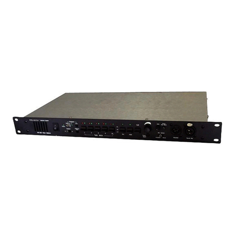
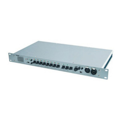
Telikou TM-800 User manual

TELIKOU Intercom System
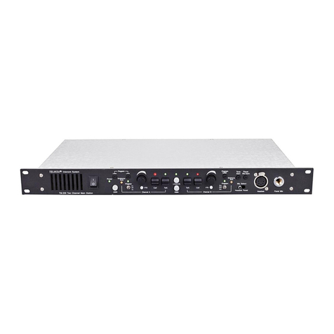
TM-800 Main Station
Instruction Manual
© TELIKOU Systems
All Rights Reserved

TELIKOU TM-800 Eight Channel Main Station
1
I. Introduction
Thank you for choosing TELIKOU intercom product. TM-800 main station is suitable for television
station, communication center, UB truck, live performance and any other environment which
requires communication. We recommend you read through this manual to better understand the
functions of TM-800。
This system adopts wired connection, and has following features, free of external emission
interference, stable and reliable performance, flexible configuration, full-duplex communication,
clear and loud communication sound, easy operation, and strong noise resistance.
II. Characteristics
Remote Microphone kill function (RMK).
IFB function
Announcement output
Controllable background input
Automatic circuit short protection and indication.
Special Feedback control circuit
III. Basic operations
Front Panel
1. Panel Microphone Connector
Ø6.35mm microphone jack can be used as unbalanced dynamic or electret microphone.
Pin definition:
S --- Shield
R --- Common
T --- Microphone Hot

TELIKOU TM-800 Eight Channel Main Station
2
2. Headset connector
4-pin XLR Male or 5-pin XLR Female
Earphone: Dynamic 8-300 ohm
Microphone: Dynamic 200 ohm
The wiring of headset is as follow:
Pin 1 --- Mic. common
Pin 2 --- Mic. hot
Pin 3 --- Earphone -
Pin 4 --- Earphone +
Pin 5 --- NULL
3. Mic Select Switch
Set the Mic select switch to select whether the panel microphone or the headset microphone is
active.
4. Announcement Button (ANN) and Indication LED
When this button is pressed on, microphone signal is sent to ANN. Out connector at rear panel.
The button also lights.
5. Call Button
Press call button will sent a call signal to all the activated channels. The channel button lights
RED.
6. TALK / IFB Button for Channel 5-8
These buttons are involved with DIP-switch which is at rear panel.
A) When DIP10 is OFF
The function of channel 5-8 is same as channel 1-4. When any channel TALK button is
pressed, the button lights green color.
B) When DIP10 is ON
IFB function is activated. Channels 5-8 become four IFB channels. Any channel TALK
button of 5-8 is pressed ON, the channel 1-4 are turned off automatically, also background
input. Only microphone signal is sent to the channel.
The working mode for TALK / IFB Button:
PTT: Hold the button, the channel is connected, release the button, the channel is cut off;
LATCH: Quick single press the button in 200ms, the channel is latched on. Press button again,
the channel is cut off.

TELIKOU TM-800 Eight Channel Main Station
3
7. TALK Button for Channel 1-4
Press channel TALK button, the microphone signal is sent to corresponding channel. The
button lights GREEN.
The working mode for TALK Button:
PTT: Hold the button, the channel is connected, release the button, the channel is cut off;
LATCH: Quick single press the button in 200ms, the channel is latched on. Press button again,
the channel is cut off.
8. Program Feed
Turn on the switch will sent external input signal to intercom channel.
ON: Activated channel always receives external program signal.
OFF: Cut off external program signal into the system.
INT: Only received when all channel are turned off.
IF any channel button is turned On, the program input will be interrupted.
9. Program Feed LED
This LED lights when Program Feed function works.
10. Program Level Control
Adjust program audio level which sent into channels.
11. Power
Power switch
12. Power LED
Red LED constantly lights when power supply working properly. If any circuit short problem
occurs, it keeps flashing until the problem has been solved.
13. Tone Alert Level Control
When TM-800 receives external call signal, the internal buzzer will sent a hum to panel speaker
and earphone. This knob adjusts the hum level.
14. Program Listen Level Control
This knob is used to adjust the volume level of background program level which heard from
earphone and speaker.

TELIKOU TM-800 Eight Channel Main Station
4
15. Remote Mic Kill Switch (RMK)
Microphone on belt pack may forget to be turned off by operators. Noise will disturb the whole
intercom system.
The Remote Microphone Kill (RMK) switch will turn off the microphone of every beltpack
remotely. If the Talk Functions of a large number of belt packs have inadvertently been left
activated, incidental noise and talking can make it difficult or impossible to communicate on the
intercom system. The Remote Microphone Kill switch can be pressed to quiet the line in this
situation.
16. Listen Level Control
This control is used to adjust the audio level which heard in headset and panel speaker.
17. Sidetone zero-adjusting
The TM-800 uses full-duplex audio in which the talk and listen audio are sent and received on
the same line. Thus, when you talk on a channel, you will also here your own voice back in the
speaker or earphone. This is called sidetone. Sidetone could cause unwanted feedback, since
the microphone may pick up your returned voice audio and re-amplify it. In either of these cases,
you should minimize the amount of sidetone.
Typically, different sidetone null settings are needed depending upon whether you are using the
gooseneck panel microphone along with the speaker or not. Use one the following procedures
to correctly set the sidetone level controls.
A) Sidetone Adjustment Procedure for Gooseneck Microphone with Speaker turned on:
1 Turn on the Mic switch. Set Mic select switch to panel.
2 Turn the level control to a comfortable level.
3 Speak into the microphone while turning the sidetone null control slowly back and forth. There
should be a point where your voice (and any accompanying acoustic feedback) is the lowest.
This is the null point.
B) Sidetone Adjustment Procedure for Headset:
1 Turn on the Mic switch. Set Mic select switch to headset.
2 Turn the level control to a comfortable level by having someone talk to you from another
station.
3 Speak into the microphone while turning the sidetone null control slowly back and forth. There
should be a point where your voice (and any accompanying acoustic feedback) is the lowest.
This is the null point.

TELIKOU TM-800 Eight Channel Main Station
5
C) System Sidetone Adjustment
1 Turn off all the microphones on sub-stations and belt packs.
2 Followed by A) and B), adjust sidetone on TM-800 main station.
3 Turn on the microphone on sub-station and belt packs one by one, and then adjust the
Sidetone to satisfied level.
The different cable length effects the result.
Please reference the following table, to have proper DIP 11 and DIP 12 setting.
Note:
We suggest do not use panel gooseneck microphone and panel speaker to adjust
sidetone.
18. Panel Mic Gain
It is used to adjust panel microphone gain to achieve proper microphone output level. It does
not affect headset microphone’s sensitivity.
The gain has pre-set as electret microphone as default. If panel microphone is changed, please
re-adjust panel Mic. gain.
19. AC Power Connection and Power Switch
Input 90V-260V, 50-60Hz AC, and the power consumption is less than 45VA.
20. Termination switch
When this switch is turned to ON position, one 300ohm termination resistor will be connected to
intercom line. If the intercom system is not terminated, the level of intercom line will be too high,
and the system stability will be influenced. However, only one termination point is allowed within
same intercom line. If multiple termination points are used incorrectly, the driving load will be
aggravated, and the level of intercom line will be too low.
This switch is set to ON position by factory default. Before using, you should set it to ON or OFF
position according to the actual connection of intercom line.
21. Channel 1-4 Intercom Line connector
3-pin XLR male socket, The pin-out of the intercom connectors is as follows:
Pin 1 --- Common (Shield)
Cable Length
<100m
100-200m
200-400m
>400m
DP11
OFF
ON
OFF
ON
DP12
OFF
OFF
ON
ON

TELIKOU TM-800 Eight Channel Main Station
6
Pin 2 --- Power (+24 VDC)
Pin 3 --- Audio
22. Channel 5-8 Intercom Line connector and IFB Output
3-pin XLR male socket, The pin-out of the intercom connectors is as follows:
Pin 1 --- Common (Shield)
Pin 2 --- Power (+24 VDC)
Pin 3 --- Audio
23. Function DIP Setting
12 digits dipper has following settings:
DIP1 - DIP8 (Program Feed into):
On: Enable background program signal sent to Intercom channel
Off: Disable background program signal sent to Intercom channel
DIP9 (Call on Talk)
On: Enable auto call function. When Talk switch is turned on, it automatic sent a call signal
to Intercom channel
Off: Disable auto call function.
DIP10 (IFB Enable):
On: Enable IFB function. Channel 5-8 become IFB channel. If talk button of any IFB channel
is turned on, channel 1-4 will be turned off automatic. Microphone signal is only sent to
the IFB channel which is turned on.
Off: Disable IFB function.
DIP11 (Long line1)
On: Sidetone compensate for long distance intercom line cable
Off: disable compensate
DIP12 (Long line2)
On: Sidetone compensate for long distance intercom line cable
Off: disable compensate
24. Program Input
External audio signal is sent into intercom line through Prog. In connector when Program Feed
To Switch is turned on. The program level can be adjusted by the Program Level Control. When
Mic Switch is activated, this program input is automatically cut off.
Cable Length
<100m
100-200m
200-400m
>400m
DP11
OFF
ON
OFF
ON
DP12
OFF
OFF
ON
ON

TELIKOU TM-800 Eight Channel Main Station
7
XLR-3F balanced input. Differential input: 1Vp-p.
The pin-out of the Program Input connector is as follows:
Pin 1 --- Common (Shield)
Pin 2 --- + Audio
Pin 3 --- - Audio
30. Announce Out
This connector is 3-pin XLR male. Differential output: 1Vp-p.
The pin-out of Announce Out is as follows:
Pin 1 --- Common (Shield)
Pin 2 --- +Audio
Pin 3 --- -Audio
IV. Installation and cable
1. Installation
TM-800 main workstation adopts 19-inches 1U cabinet, and this workstation can be mounted on
rack or placed on desktop.
2. Intercom cable
A). Rules for cable selection
TELIKOU intercom system adopts double-core shielded audio cable, one core is used for
transmitting audio signal, another core is used for transmitting DC power or control signal, and the
shielded layer is used as common line for audio and power supply. To decrease resistance of
common line and crosstalk interference, the cable with larger cross section area should be used.
When it is used in fixed way, the cross section area of single line should be at least 1.5mm2, when it
is used in mobile mode, the cross section area of single line should be at least 0.75mm2. When the
cable is longer, the cross section area of cable should be larger. If the cable has more than 2 cores,
it is recommended to use the additional core as common line.
B). Cable connection
The standard TELIKOU intercom cable is connected with a pair of 3-pin XLR connectors. If longer
cable is required, you can connect several cables together with head-end method.
The wiring of connector is as follows:
Pin 1 --- Common (Shield)
Pin 2 --- Power or Control Signal
Pin 3 --- Audio Signal
Notice: the pin-1 GND connection for each XLR connector must be insulated from cabinet, and

TELIKOU TM-800 Eight Channel Main Station
8
cannot be connected to shell of XLR connector.
V Troubleshooting
Problem: Power LED wink
Cause 1: Direct short on the intercom channel
Solution 1: Remove all the intercom cables from TM-800. Check each channel one by one, until find
the short channel.
Cause 2: Overload
Solution 2: Decrease the amount of remote stations.
Problem: System feedback (Acoustical)
Cause 1: Listen level control at this station or a remote station is set too high
Solution 1: Reduce the volume
Cause 2: Sidetone null control at this station or a remote station is not adjusted correctly
Solution 2: Adjust sidetone again.
Cause 3: Channel un-terminated.
Solution 3: Set the TM-800 termination switch to the ON position.
Cause 3: A headset cord is too long or jointing quality.
Solution 3: Check headset cord
Problem: Excessive crosstalk
Cause 1: High DC resistance in ground return.
Solution 1: Use heavier cable; add additional conductor(s) to ground return.
Cause 2: Headset cables are not wired properly or shielded properly.
Solution 2: Correct wiring. Use headsets with properly shielded wiring.
Problem: Low Listen Level
Cause 1: Some microphone on belt pack or stations are no turned off after talking. The
noise goes into the system through these microphone.
Solution 1: Press RMK to shut off all the microphone in the system.
Problem: Hum or buzz in system
Cause 1: Inductive pickup caused by close proximity of this main station or connected remote

TELIKOU TM-800 Eight Channel Main Station
9
stations to power lines or transformers.
Solution 1: Relocate the offending unit.
Cause 2: Intercom line cable is not wired properly; the shield of microphone cable is not connected
to Pin-1 of 3-XLR
Solution 2: Check intercom line cable. Make sure all the cables’ Pin-1 of 3-XLR connects correct.
If this condition occurs, it is because the system ground came into contact with something
that was "HOT" with respect to the power supply earth ground. Carefully check the system
ground and AC distribution in the area.
WARNING: THIS IS A POTENTIALLY DANGEROUS SITUATION. A SHOCK HAZARD MAY
EXIST BETWEEN A REMOTE STATION HEADSET AND GROUND.
VI Technical Specification
BANDWIDTH:
300Hz-4000Hz ±3dB
SIDETONE:
Adjustable range: >32dB
EARPHONE:
Dynamic 8 - 300ohm
HEADSET MICROPHONE:
Dynamic 200-600 ohm
POWER SUPPLY:
AC 90-260V, 50-60Hz, <45VA
DIMENSION:
19” (W) x1.75” (H) x9.48” (D), 482mm x 44.5mm x 241mm
WEIGHT:
2.6kg
Other manuals for TM-800
1
Table of contents
Other Telikou Intercom System manuals

Telikou
Telikou BK-601 User manual

Telikou
Telikou BK-1200 User manual

Telikou
Telikou SKYLINE SK-100 User manual

Telikou
Telikou FM-804 User manual

Telikou
Telikou TM-800 User manual

Telikou
Telikou BK-501 User manual

Telikou
Telikou BK-501 User manual

Telikou
Telikou MS-200 User manual

Telikou
Telikou FT-800 User manual

Telikou
Telikou TM-200 User manual

Telikou
Telikou UTS-200 User manual

Telikou
Telikou BK-804 User manual

Telikou
Telikou DT-100 User manual

Telikou
Telikou MDS-400 User manual

Telikou
Telikou TM-200 User manual

Telikou
Telikou BK-101 User manual

Telikou
Telikou BK-104 User manual

Telikou
Telikou FT-800 User manual

Telikou
Telikou IP-1X User manual

Telikou
Telikou TF-204 User manual