Telpro PaneL Lift 439 User manual

OPERATOR’S MANUAL
MADE BY
®
Covered by one or more of the following patents: 3,828,942 5,368,429 5,586,619 5,984,605 7,556,464 7,726,901 Other patents pending.
© 2013 Telpro Inc. All Rights Reserved.Form 42-04-00-00 version 2b
Read and become familiar with this manual BEFORE operating unit.
WARNING
For Model 439
Before operating this equipment, thoroughly read this set of instructions, make sure you
understand them, and only then follow the step-by-step directions. Failure to do so could
result in serious property damage and / or serious bodily injury.
Warning
Read and follow these warnings and the instructions that follow. Failure to do so could
result in serious property damage and/or serious bodily injury.
• Use and maintenance of the PANELLIFT®Drywall Lift shall be
limited to authorized personnel who are trained in the proper
techniques for its safe operation and maintenance and who are
familiar with the various hazards of overhead material handling.
• As with any lifting equipment, ALWAYS WEAR A HARD HAT
when operating the PANELLIFT®Drywall Lift and keep children
away from the work area. Failure to do so could result in serious
bodily injury.
• DO NOT ATTEMPT TO USE YOUR PANELLIFT®Drywall Lift
IF ANY PART IS MISSING, DAMAGED OR WORN. ORDER A
REPLACEMENT PART IMMEDIATELY. Using a PANELLIFT®
Drywall Lift with missing, damaged or worn components can
result in failure of the unit and possibly severe property damage
and/or serious bodily injury.
• INSPECT THE CHAIN ASSEMBLIES BEFORE EACH USE.
REPLACE AT THE FIRST SIGN OF DAMAGE OR WEAR. A
worn, damaged or improperly installed chain can fail resulting in
a sudden and rapid lowering of the lift and the load and possibly
resulting in serious property damage and/or serious bodily injury.
Inspect the chains by extending the lift fully and examining the
full length of each lift chain for signs of damage or wear.
• The weight capacity of the PANELLIFT®Drywall Lift is 200
lbs. (90 kg). DO NOT load the unit beyond this limit. When
loading wallboard (or similar building panels), load only
one sheet of wallboard at a time. Failure to follow this warning
can result in an unstable load and/or damage to the PANELLIFT®
Drywall Lift contributing to a sudden failure of the machine and
serious property damage and/or serious bodily injury.
• DO NOT TAMPER WITH OR ADJUST the torque setting on
the load limiting clutch of the PANELLIFT®Drywall Lift. This is
factory preset for the load range of the intended use of the lift.
Altering this factory setting can subject the drive, lift, and brake
mechanisms of the lift to stresses and loads that they were not
designed to carry. This can result in failure of the unit which
may include a sudden and rapid lowering of the lift and the load
possibly resulting in serious property damage and/or serious
bodily injury.
• DO NOT ROLL a loaded PANELLIFT®Drywall Lift while the
load is raised. Always keep the load lowered until the lift is in
place beneath the space in which the load will be installed. Rolling
a PANELLIFT®Drywall Lift while the load is raised can result
in tipping the lift and load possibly resulting in serious property
damage and/or serious bodily injury.
• Operate the PANELLIFT® Drywall Lift only on hard, flat, level sur-
faces free of obstructions, debris, clutter, pits, holes or openings.
Failure to follow this warning can result in tipping the lift and/or
load possibly resulting in serious property damage and/or serious
bodily injury.
• The PANELLIFT®Drywall Lift is designed exclusively as
a material lift and shall be used for no other purpose. The
PANELLIFT®Drywall Lift is not a personnel lift or platform and
shall not be used as such. Using the PANELLIFT®Drywall Lift for
purposes other than a material lift can subject the unit to stresses
and loads that it was not designed to carry. This can result in
failure of the unit which may include a sudden and rapid lowering
of the lift and the load possibly resulting in serious property
damage and/or serious bodily injury.
• The PANELLIFT®Drywall Lift is made of steel which conducts
electricity. Keep the unit away from live electrical wires. Failure to
do so could result in electrocution.
• Use only factory authorized replacement parts. Installation of
other parts can compromise the safe design of the PANELLIFT®
Drywall Lift and may cause failure of the unit possibly resulting in
serious property damage and/or serious bodily injury.
• Moving the PANELLIFT®Drywall Lift from a cold environment to
a warm one may cause condensation to form on metal surfaces
creating a potential for malfunction. Such malfunction could
possibly result in serious property damage and/or serious bodily
injury: Allow the unit to reach working room temperature and
check to make sure that the winch brake drum is clean and dry
before operating.
• CAUTION: When the winch brake is released the winch will
rotate backward and cradle will rapidly descend. If the winch is
allowed to free-wheel backward, the winch handle can develop
a great deal of rotational speed and potential for injury. To avoid
possible serious personal injury or property damage always
control the winch wheel firmly with the right hand before releasing
the brake. SEE INSTRUCTIONS ON PAGE 6
• DO NOT pass your hand through the spokes on the winch
when operating the unit as this could result in serious bodily
injury.
• Keep hands, hair, and clothing away from chains and movable
telescoping sections.
• BEFORE operating this equipment, thoroughly read
this set of instructions, make sure you understand them,
and only then follow the step-by-step directions.
FAILURE TO READ AND FOLLOW THESE
INSTRUCTIONS could result in failure of the
equipment. Failure of the equipment while the lift is
raised can include a sudden and rapid lowering of
the lift and load possibly resulting in serious property
damage and/or serious bodily injury.
Questions? - Call Telpro Inc. Customer Service at 1-800-448-0822 or 701-775-0551
- 1 -
USER COMPONENTS & SPECIFICATIONS
- 2 -
SEE PAGE 1 FOR IMPORTANT OPERATIONAL WARNINGS
NET WEIGHT
LOADING HEIGHT
MAxIMUM HEIGHT 14’ 5” (439 cm)
15’ 11” (485 cm) w/ optional 18” extension
LOAD RATING 200 lbs. (90 kg) DO NOT EXCEED.
SHEET QUANTITY CAPACITY Single
37” (94 cm)
Approximately 124 lbs. (56 kg)
A
B
C
D
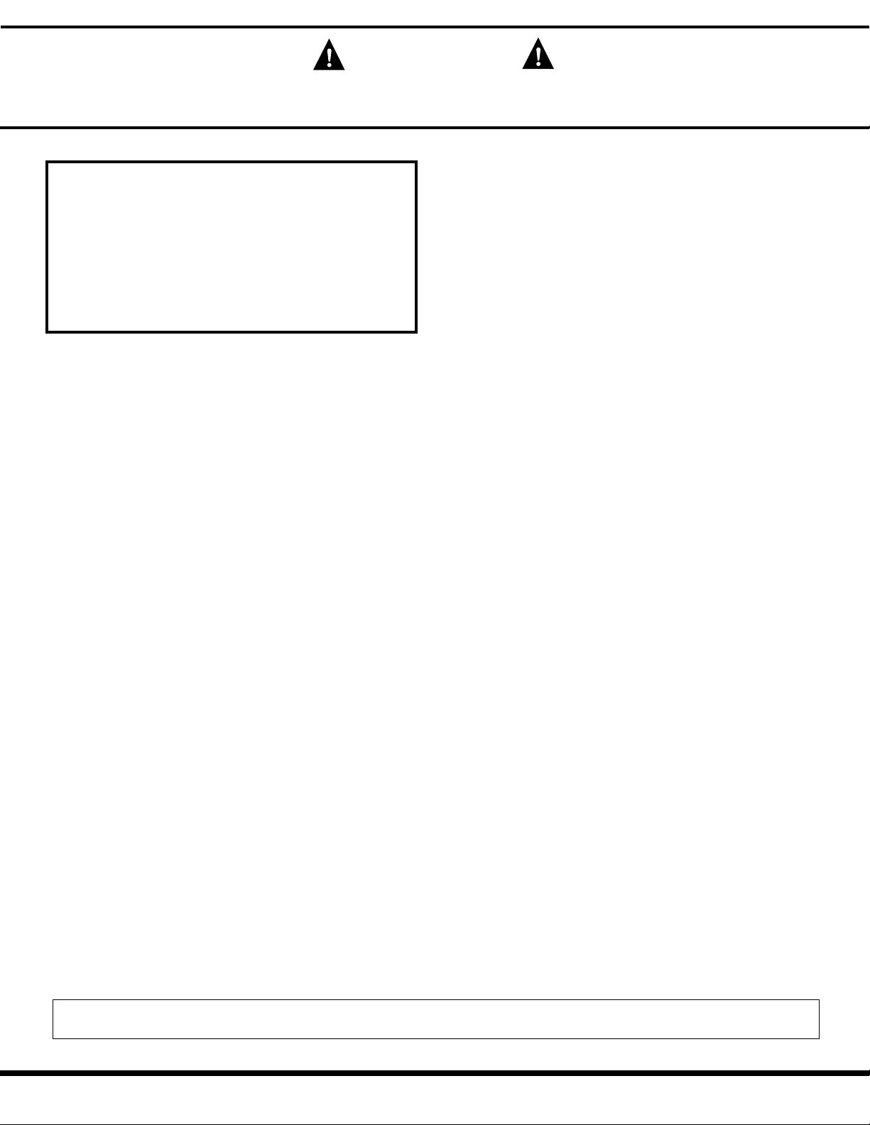
A. Cradle Assembly - less detachable cross arms
B. Cradle Cross arms ( 1 pair )
C. Frame Assembly with winch and telescoping sections
D. Tripod Base Assembly

AB
DC
1. Begin by setting up the tripod base: press down on the
slide yoke pin clip and swing the outer legs out until they lock
in the working position (note the holes on the bottom of the
slide tube).
2. Set the backstop as shown to hold the tripod in place
when attaching the frame.
3A. Place the frame assembly on the tripod base.
ASSEMBLY
- 4 -
3B. Pocket “A” slides OVER angle “B” while angle “C”
slides INSIDE angle “D”.
3C. When the frame is correctly positioned on the tripod
base release the backstop.
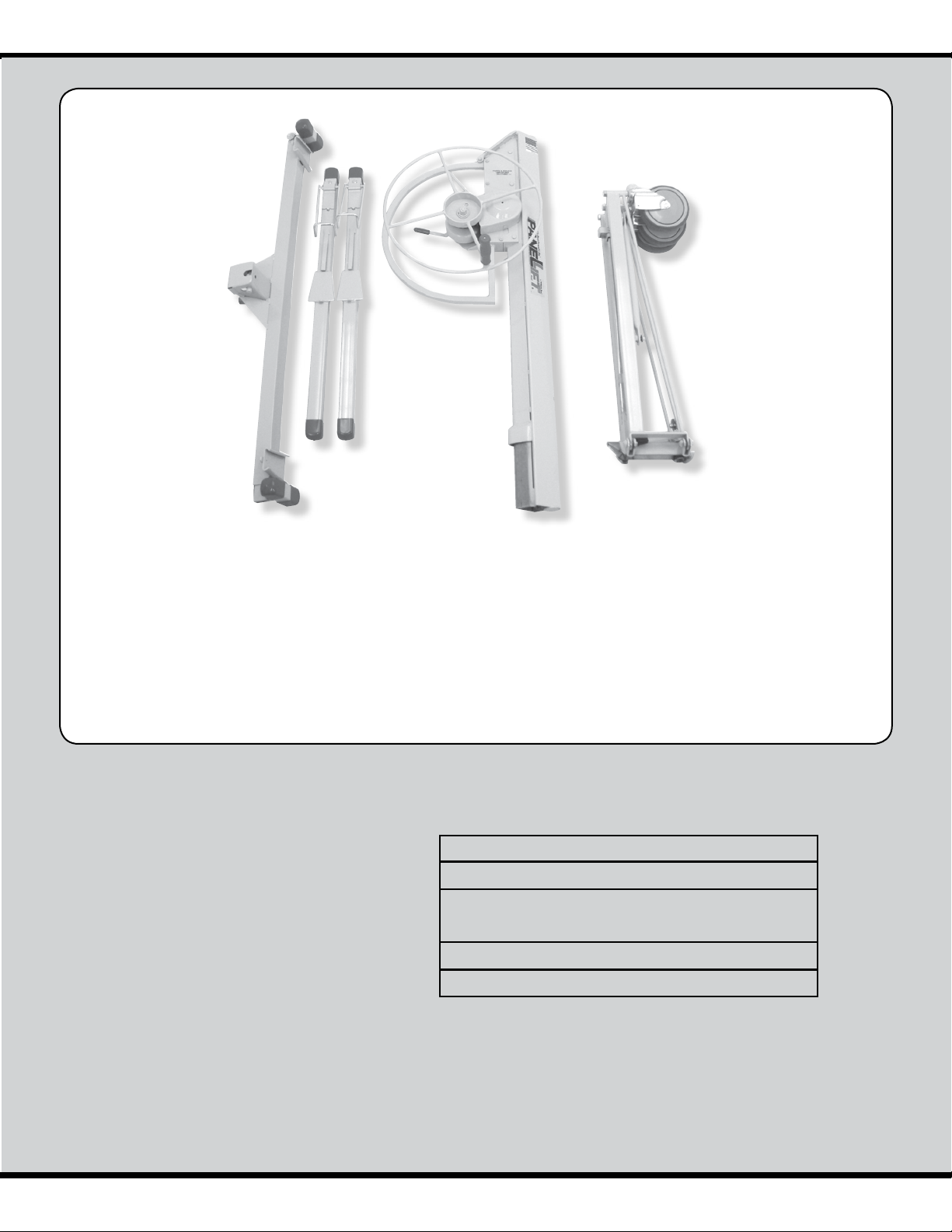
4A. Release the telescoping section retaining hook by rotating
the winch wheel forward with your right hand while raising the
brake arm with your left hand.
ASSEMBLY continued
- 5 -
4B. Hold the brake arm in the raised position and allow
the winch wheel to find a neutral position.
Pull
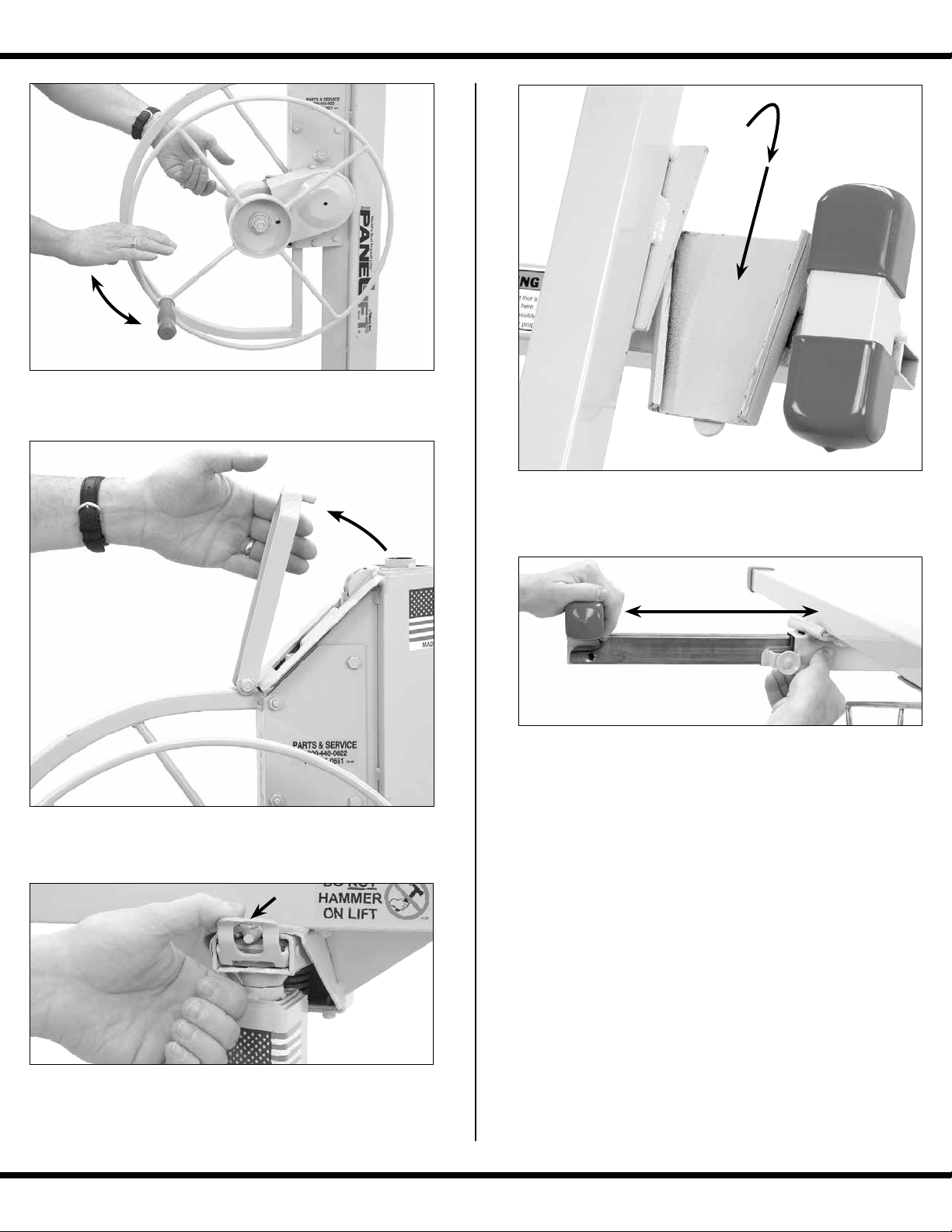
6. Place the tapered plates of the cross arms into the
tapered sockets on the cradle. The spring tab on the
back of the cross arm will lock it into place.
7. To extend the outriggers for use, pull out on the outrig-
ger lock pin with your right hand and slide the outrigger
out with your left hand as shown. The lock pin will engage
at three different points on the outrigger: fully retracted,
extended 21”, or extended 33”. MAKE SURE that the lock
pins are engaged in one of these three positions before
loading the unit. DO NOT use the PANELLIFT®with the
outriggers extended beyond the 33” point.
Retract the outriggers when storing or transporting
the unit.
4C. Release the brake arm and swing the retaining hook
to the open position.
5. Mount the cradle on top of the telescoping section.
Flip out the tilt latch to allow the cradle to tilt for loading
and for hanging drywall on sidewalls and sloped ceilings.
Table of contents
Other Telpro Lifting System manuals


Popular Lifting System manuals by other brands

probst
probst SDH-H-15 operating instructions

Bruno
Bruno OUTDOOR ELITE CRE-2110E Operator's manual

matev
matev FPS Mounting Assembly Installation Guide

Vestil
Vestil CYL-HLT Series instruction manual

Butts Tools
Butts Tools BXS0002 operating instructions

Safelift
Safelift MoveAround MA60 Original instructions


R. Beck Maschinenbau
R. Beck Maschinenbau HS 600 operating manual

Nova Technology International, LLC
Nova Technology International, LLC NAS Series quick start guide

Genie
Genie Z-60/34 Operator's manual

Screen Technics
Screen Technics INTERFIT Vertical Up Lift instructions

Drive
Drive DUPONT SAMERY Hermes user manual

Custom Equipment
Custom Equipment Hy-Brid 3 Series MAINTENANCE & TROUBLESHOOTING MANUAL