Teltonika T-BoxN12R User manual

TELTONIKA T-BoxN12R
TBN-107
USER’S MANUAL V1.13

2
Contents
1. About this document...............................................................................................................................5
2. Introduction..............................................................................................................................................6
3. Mechanical integration............................................................................................................................7
3.1. Package contents..............................................................................................................................7
3.2. Dimensions .......................................................................................................................................7
3.2.1. T BoxN12R case.......................................................................................................................7
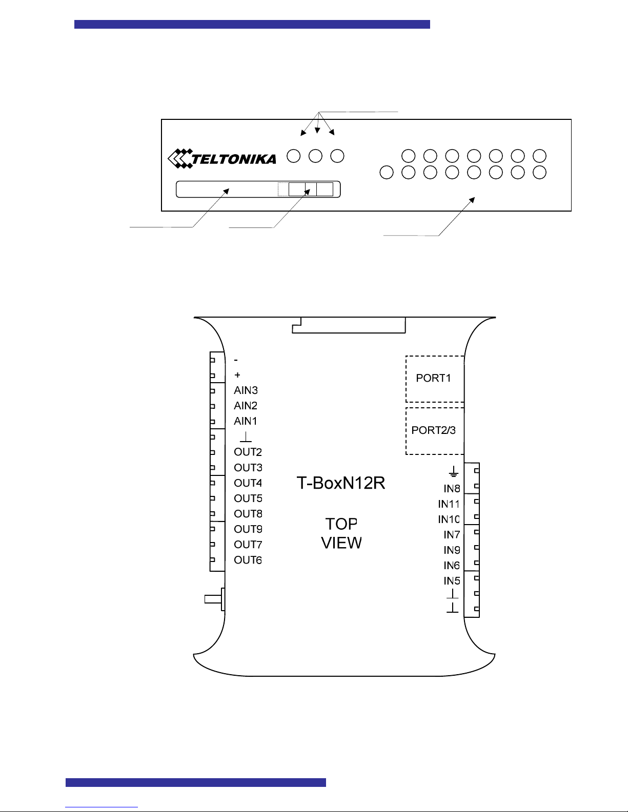
3.2.2. Front panel ................................................................................................................................8
3.2.3. Top view ....................................................................................................................................8
4. Electrical integration................................................................................................................................9
4.1. Electrical characteristics ..................................................................................................................9
4.1.1. Connector pin out....................................................................................................................9
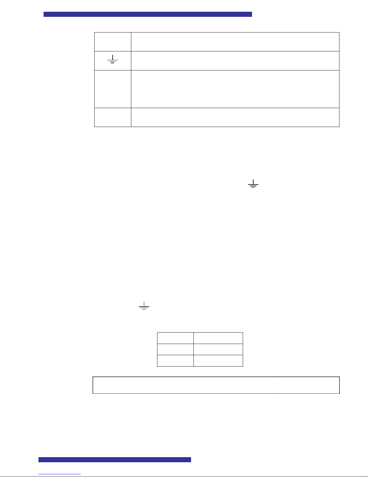
4.1.2. Grounding ...............................................................................................................................10
4.1.3. Power supply...........................................................................................................................10
4.2. I/O characteristics .........................................................................................................................10
4.2.1. Digital Inputs...........................................................................................................................10
4.2.2. Digital Outputs .......................................................................................................................11
4.2.3. Analog Inputs..........................................................................................................................11
4.3. Serial communication ....................................................................................................................11
4.3.1. PORT 1....................................................................................................................................12
4.3.2. PORT 2....................................................................................................................................13
4.3.3. PORT 3....................................................................................................................................13
4.3.4. Pin out description of the serial port connectors..............................................................13
4.4. Sample electrical connection.........................................................................................................14
4.4.1. Sample scheme........................................................................................................................14
5. JAVA (J2ME) Overview.......................................................................................................................15
5.1. Introduction....................................................................................................................................15
5.2. Supported Java API .......................................................................................................................15
6. M2M System protocol overview..........................................................................................................16
7. Introduction to integrated TCP/IP stack...........................................................................................17
8. Documents provided by Nokia ...........................................................................................................18
9. Software...................................................................................................................................................19
9.1. Nokia 12 Configurator ..................................................................................................................19
9.2. Modem Drivers for Nokia 12.......................................................................................................19
9.3. Nokia 12 IMP 1.0 Concept Simulator.........................................................................................19
9.4. Eclipse..............................................................................................................................................19

3
10. Troubleshooting...................................................................................................................................20
10.1. T BoxN12R doesn’t power up...................................................................................................20
10.2. Nokia Configurator couldn’t connect to T BoxN12R...........................................................20
11. Technical specifications ......................................................................................................................23
11.1. Mechanical specifications and operating conditions...............................................................23
11.2. Electrical parameters....................................................................................................................23
12. Technical support ................................................................................................................................25

4
Leg l Notice
Copyright © 2004 Teltonika.
All rights reserved. Reproduction, transfer, distribution or storage of part or all of the
contents in this document in any form without the prior written permission of Teltonika is
prohibited.
Nokia and Nokia Connecting People are registered trademarks of Nokia
Corporation.
Java and all Java based marks are trademarks or registered trademarks of Sun
Microsystems, Inc.
Other product and company names mentioned herein may be trademarks or trade
names of their respective owners.

5
1. ABOUT THIS DOCUMENT
This document describes the T BoxN12R hardware integration, configuration and
software configuration. This document should help T BoxN12R integrators to integrate
and configure the system.
The document describes the mechanical, electrical, radio frequency (RF), antenna
installation, PC software installation and configuration.
Document also describes how to test and run T BoxN12R for the first time.
Note: Form more detail information integrator should be familiar with following documents: Nokia
12 Hardware Integrators Manual, Nokia M2M Platform Software eveloper’s Guide, and Nokia 12
GSM Module IMlet Programming Guide. These documents you can download from Nokia web site
(www.forum.nokia.com/m2m)

6
2. INTRODUCTION
T BoxN12R was designed for M2M (machine to machine) applications or other
wireless solutions. Integrated Nokia 12 GSM module enables flexible wireless
communication over GSM network. Nokia 12 supports various communication bearers:
• EDGE multi slot class 2 (2+1) and mobile station class B
• GPRS multi slot class 6 (3+1, 2+2, 2+1) and mobile station class B
• CSD
• HSCSD
• SMS, text/data messaging
• USSD, data messaging
Nokia 12 also supports Java (J2ME) and CORBA. These features enable
development of distributed wireless applications.
The T BoxN12R has several operating modes, so it can be used for different
applications. In AT mode it can be used as a wireless modem for PC to connect to the
Internet. In I/O mode T boxN12R can control external hardware by reading/writing I/O
with a Java application or SMS. The functionality of T BoxN12R can be expanded by
connecting external hardware (controllers for Real Time operation) to RS 232 interface.
All these features enable to use T BoxN12R in wide range of applications.

7
3. MECHANICAL INTEGRATION
3.1. Package contents
These are the contents of your package:
1) T BoxN12R,
2) Serial cable PORT1/2 (one connector – female COM port, another – RJ45),
3) Serial cable for PORT3 (one connector – female COM port, another – RJ45),
4) GSM antenna (SMA connector),
5) 6x connectors MSTB 2,5 HC/3 ST, 3x connectors MSTB 2,5 HC/2 ST
(could be additionally purchased from Teltonika or
www.phoenixcontact.com),
6) A CD with Software and User’s Manual.
3.2. D mens ons
3.2.1. T-BoxN12R case
The plastic case of T BoxN12R is light and suitable for fitting with electronic
instruments that can hook to the DIN EN 50022.
When a place for T BoxN12R is being planned, it should be considered that GSM
antenna, which is supplied in your package, should NOT be placed in metal case. The
supplied antenna usually has 2 meter length cable, so if you plan to mount T BoxN12R
into a metal case, please mount the antenna outside the metal case. If cable length of 2
meters is not enough, contact our sales department (refer to page 25) to order antennas
with longer cables.
22,55mm
101mm
120mm

8
3.2.2. Front panel
3.2.3. Top view
5
6
7
8
9
10
11
2
3
4
5
6
7
8
9
PWR AT SLEEP
IN
OUT
T-BOX/N12R
I/O AT
Switch
Indication LEDs
I/O LEDs
SIM card slot

9
4. ELECTRICAL INTEGRATION
4.1. Electr cal character st cs
4.1.1. Connector pin-out
Table 1. Connector p n-out
P n name
Descr pt on
GND
+ Device power. Voltage range from 9V to 30V DC. Power consumption:
Stand by mode ~30mA@12V, peak up to 700mA@12V. As switched power
regulator is used inside, the smaller the voltage, the bigger the current and
vice versa (power consumption remains about the same)
AIN3 Analog input 3. Input range from 0 to 10V
AIN2 Analog input 2. Input range from 0 to 10V
AIN1 Analog input 1. Input range from 0 to 10V
┴ GND
OUT2 Output 2. Open collector output (max. load 70mA or 200mW)
OUT3 Output 3. Open collector output (max. load 70mA or 200mW)
OUT4 Output 4. Open collector output (max. load 70mA or 200mW)
OUT5 Output 5. Open collector output (max. load 70mA or 200mW)
OUT8 Output 5. Open collector output (max. load 70mA or 200mW)
OUT9 Output 9. Open collector output (max. load 70mA or 200mW)
OUT7 Output 7. Open collector output (max. load 70mA or 200mW)
OUT6 Output 6. Open collector output (max. load 70mA or 200mW)
┴ GND
┴ GND
IN5 Input 5. This input is optically isolated and connected to corresponding
Nokia 12 input. 0…1V – false, 2…24V – true.
IN6 Input 6. This input is optically isolated and connected to corresponding
Nokia 12 input. 0…1V – false, 2…24V – true.
IN9 Input 9. This input is optically isolated and connected to corresponding
Nokia 12 input. 0…1V – false, 2…24V – true.
IN7 Input 7. This input is optically isolated and connected to corresponding
Nokia 12 input. 0…1V – false, 2…24V – true.
IN10 Input 10. This input is optically isolated and connected to corresponding
Nokia 12 input. 0…1V – false, 2…24V – true.
IN11 Input 11. This input is optically isolated and connected to corresponding
Nokia 12 input. 0…1V – false, 2V – true.

10
IN8 Input 8. This input is optically isolated and connected to corresponding
Nokia 12 input. 0…1V – false, 2V – true.
Input ground. Input ground is separate from module ground (power supply,
outputs) because inputs are optically isolated.
PORT2/3 Serial port 2. Connected to Nokia 12 port 2. Can be used as system port
(M2M protocol to configure Nokia 12) only
Serial port 3. Connected to Nokia 12 port 3. This port is controlled by Java
application on the Nokia 12 module or GPS.
PORT1 Serial port 1. Connected to Nokia 12 port 1. Can be used for AT commands,
GPS or as system port.
4.1.2. Grounding
The ground for power supply is marked as “ “, for analog inputs and outputs is
marked with symbol ┴. These pins are connecter together internally.
The input ground is isolated from ┴. Internally all ┴ pins are connected together.
In case optical isolation is not needed the ┴ and can be connected together.
4.1.3. Power supply
The T BoxN12R uses switched power regulator. Acceptable voltage range is from
9V to 30V DC.
Power consumption: Stand by mode ~30mA@12V, peak up to 700mA@12V. The
smaller the voltage, the bigger the current and vice versa (power consumption remains
about the same).
4.2. I/O character st cs
4.2.1. igital Inputs
Inputs are optically isolated. Input ground is separated from common device ground
and marked as . If voltage is applied between 1 V and 2 V, the logical value depends
on voltage history, because digital input has hysteresis.
Table 2. Log cal values for voltages of d g tal nputs
Voltage Log cal value
0 – 1 V 0 (False)
2 – 24 V 1 (True)
Note: When T-BoxN12R operates n AT mode (sw tch s n pos t on “AT”)
outputs 2,3,4,5 and Inputs 5 and 6 are d sabled!

11
4.2.2. igital Outputs
T BoxN12R has open collector outputs. The picture below shows the internal circuit
diagram of outputs implementation:
Outputs can drive up to 70mA or 200mW load. The circuit has protection diode so
outputs can directly drive relays.
Note: When T-BoxN12R operates n AT mode (sw tch s n pos t on “AT”)
outputs 2,3,4,5 and Inputs 5 and 6 are d sabled!
4.2.3. Analog Inputs
Analog inputs are designed to measure voltage in range from 0 to 10 V. As this input
voltage is internally divided by 2,8, the measured values by Nokia 12 will be vary from 0 to
2,7 V.
The analog inputs have protection diodes, which protect the device from too high
voltage and negative voltage.
4.3. Ser al commun cat on
T BoxN12R provides 3 serial communication ports:
Serial port 1. Connected to Nokia 12 port 1. This port can be used for AT
commands, GPS or as system port.
Serial port 2. Connected to Nokia 12 port 2. This port can be used as system port
(M2M protocol to configure Nokia 12) only
Serial port 3. Connected to Nokia 12 Port 3. This port is controlled by Java
application on the Nokia 12 module or GPS.
There are only two RJ45 serial port connectors on the housing, which are marked as
PORT1 and PORT2/3. As you can see, PORT2 and PORT3 share the same connector.
This, at first glance unusual, solution was made, because usually PORT2 is used for device
configuration only and is not used during normal operation.
The package contains two serial cables, marked as “PORT 1/2” and “PORT3”.
Refer to Table 3 to choose the right cable and the right connector for the desired serial
port.
10
Ω
Output

12
Table 3. Choos ng the r ght cable and the r ght connector for the des red ser al port
Connector Cable
Cable “PORT 1/2”
Cable “PORT 1/2”
Cable “PORT 3”
Connector “PORT1” PORT1
Connector “PORT 2/3”
PORT2
Connector “PORT 2/3”
PORT3
The signal level of all serial ports is RS232.
4.3.1. PORT 1
Port 1 provides asynchronous channel. This port can be used with full 8 signal RS
232 handshaking signals. The baud rate for Port 1 may be between 1200 and 230400 bit/s.
Baud rate 230400 bit/s can be used only with AT command mode and autobauding.
Port 1 can operate in the following modes:
• GPS Receiver,
• System Protocol – for configuring T BoxN12R using M2M mode,
• AT Command Mode – for connecting Internet, configuring device using AT
mode,
• HW Detection – mode is selected by switch.
The mode of PORT1 is selected by changing settings in configuration software
(Nokia 12 Configurator, which is found in the CD) and by changing switch, which is found
on the front panel. Refer to Table 4 to see, how to choose the desired mode.
The default value for this port in configuration is HW Detection.
Table 4. Choos ng the r ght mode of sw tch and the sett ng n conf gurat on to
have the des red mode of PORT1
Configuration Switch
AT I/O
System Protocol System protocol
General IO I/O mode
AT AT mode
GPS receiver GPS receiver mode
HW detection AT mode
1
I/O mode
1
In AT mode outputs 2,3,4,5 and Inputs 5 and 6 are disabled!
Note: After changing the position of the switch, please reboot T-BoxN12R (power off and on again)
for the changes to take effect.
The T BoxN12R provides all signals for the industry standard DB9 RS 232C
connection.

13
Note: A special RJ45- B9F cable is required in order to connect the device to the PC. The cable
is supplied in the package.
4.3.2. PORT 2
Port 2 provides the second asynchronous channel with a simple handshaking
capability (only RTS and CTS). The baud rate for Port 2 can be set to 9600, 19200, 38400,
57600 or 115200 bit/s. Port 2 is the default port for using the M2M System Protocol.
However, if Port 1 is configured to use the M2M System Protocol, Port 2 cannot be used
for anything.
Note: A special RJ45- B9F cable is required in order to connect the device to the PC. The cable is
supplied in the package.
4.3.3. PORT 3
Port 3 provides the third asynchronous channel with no hardware handshakes. The
baud rate for Port 3 can be set between 1200 and 115200 bit/s.
Port 3 can be used to control external device by Java application. Also it can be
software configured to use with GPS.
Note: A special RJ45- B9F cable is required in order to connect the device to the PC. The cable is
supplied in the package.
4.3.4. Pin-out description of the serial port connectors
Table 5. PORT1 P n-out descr pt on Table 6. PORT2/3 P n-out descr pt on
RJ45 P n
number
Descr pt on
D rect on
RJ45 P n
number
Descr pt on D rect on
1 DSR Output 1 RXD (Port 3) Input
2 DCD Output 2 TXD (Port 3) Output
3 DTR Input 3 NC
4 GND 4 GND
5 RXD Input 5 RXD Input
6 TXD Output 6 TXD Output
7 CTS Output 7 CTS Output
8 RTS Input 8 RTS Input

14
4.4. Sample electr cal connect on
4.4.1. Sample scheme

15
5. JAVA (J2ME) OVERVIEW
5.1. Introduct on
Java technology enables writing applications to M2M devices in Java programming
language. These Java applications can then be downloaded over the air to M2M devices for
execution. This enables rapid application development and deployment.
Traditionally, M2M application development for remote assets had to be done with
C language. This meant that the application download and update was quite tricky. Also,
embedded C development required special software and hardware tools. Applications
developed with C language could not be executed directly within the M2M device. Instead
they required external hardware for execution.
Java applications can be developed with publicly available tools and tested with
software simulators. Due to the portable and dynamic nature of Java, Java applications can
be downloaded and updated dynamically. Also, since the Nokia 12 GSM module includes
Java Virtual Machine, the Java applications can be executed in the Nokia 12 GSM module
without external hardware.
Java is an excellent choice in an M2M application when remotely controlled I/O is
not enough. The customer can have additional logic in the Nokia 12 GSM module itself.
When the interface from the Nokia 12 GSM module to a device is purely I/O, no
complicate protocols are needed. If a separate application HW is difficult to design or
expensive to manufacture, Java enables effective application development and fast time to
market.
Form more information about programming Nokia 12 see the documentation
provided from Nokia.
5.2. Supported Java API
The Nokia 12 GSM module supports several APIs for Java application. In addition
to the APIs of the IMP profile, APIs to connect external devices using M2M system
connector capabilities are offered as well as useful additional APIs for wireless connectivity.
IMP offers also the functionality for using persistence memory and advanced application
model to make intelligent M2M solutions with the Nokia 12 GSM module.
List of supported APIs
• Wireless Messaging API (JSR 120)
• Serial API
• ORB API
• IO API
• HTTP API (included in IMP)
• Socket API
• RMS API (included in IMP)

16
6. M2M SYSTEM PROTOCOL OVERVIEW
The Nokia 12 GSM module is part of the Nokia M2M Platform solution. The M2M
system mode enables operating on the Nokia M2M Platform.
The platform connects applications in a corporate intranet to the remote assets of
the corporation utilising a selection of GSM bearers and Internet technology.
Open interfaces and support for multiple GSM bearers (and even changing the
bearers dynamically) make it possible to adjust to changes in networks, tariffs and also to
the requirements of new applications. As change is constant in the communication field, it
is important to have a certain degree of independency between the applications and the
communication technology.

17
7. INTRODUCTION TO INTEGRATED TCP/IP STACK
In data communication, there is always need for low level communication protocols
to ensure reliable data transmission. The protocol stacks are difficult and expensive to
implement so the Nokia 12 GSM module provides in build TCP/IP and UDP/IP
transport layer protocol stacks. Standard socket interface is also implemented in the Nokia
12 GSM module to enable usage of these stacks. Also client HTTP protocol is supported
for fetching www pages from a server.
TCP is a connection oriented protocol that provides a reliable flow of data between
two applications over networks supporting IP protocol. Currently, TCP/IP can be used
with GSM data calls and GPRS. The TCP/IP protocol implementation in the Nokia 12
GSM module is highly optimised for wireless networks.
The versatility of the TCP/IP protocol makes it ideal for a very wide range of
applications. TCP/IP is used in many well known applications, such as Web browsers,
Telnet, and FTP. Also, many proprietary applications use TCP/IP to transmit data reliably.
The reliable nature of TCP/IP means that the need for applications to ensure that
data transmissions succeed is minimised. TCP/IP uses a checksum mechanism to ensure
that data is transmitted without errors. Also, TCP/IP incorporates mechanisms for re
transmitting packets that get lost in networks. These features mean that the customer
applications need not to worry about the details of data transmissions. Since TCP/IP is
widely used, it is very well documented.

18
8. DOCUMENTS PROVIDED BY NOKIA
Nokia provides a full set of documents regarding M2M platform. Here is the list of
most common and recommended document. Please be familiar with these documents
before you start to integrate T Box.
• Nokia 12 Hardware Integration Manual
• Nokia 12 IMlet Programming Guide
• Nokia 12 product specification
• Nokia 12 user control mode guide
• Nokia M2M Software Developer's Guide
• Nokia 12 AT Command Guide
• M2M System Protocol 2 Specification
The most up to date version of these documents you can download form Nokia
website (www.forum.nokia.com/m2m).

19
9. SOFTWARE
9.1. Nok a 12 Conf gurator
The Nokia 12 Configurator software is used to configuration and software upload to
the module.
9.2. Modem Dr vers for Nok a 12
Modem drivers have to be installed when T BoxN12R is used as a modem for PC.
Note: When installing modem driver ensure that T-BoxN12R is connected to your PC. Modem
has to be connected to the PC during the boot of the PC. Otherwise the OS will not find the modem. This
issue is specific for particular operating systems (MS Windows XP, MS Windows 2000).
9.3. Nok a 12 IMP 1.0 Concept S mulator
Concept simulator is used for testing IMlets before loading them to module. This
helps to speed up the development of Java applications.
9.4. Ecl pse
Eclipse is an open extensible IDE, which is needed if you want to write IMlets
yourself. It could be found at www.eclipse.org .
Also you need a plug in for Eclipse, called EclipseME, which could be found at
http://eclipseme.sourceforge.net .

20
10. TROUBLESHOOTING
10.1. T-BoxN12R doesn’t power up
If the device powers up well, the “PWR” LED should be always on and output
LEDs should be blinking one after another in a row. Note: the output LEDs are
bl nk ng, because a JAVA IMlet s pre- nstalled to your T-BoxN12R. If you load
your own IMlet, t w ll not bl nk.
1) Please make sure you have connected the power supply wires to T BoxN12R
according the scheme on the device (positive terminal of power supply to pin 17 and GND
to pin15) and that these wires are firmly holding in the connector.
2) Please make sure your power supply (AC/DC converter or battery) is at least
12V and at least 500mA @ 12V.
10.2. Nok a Conf gurator couldn’t connect to T-BoxN12R
1) Please make sure that you plug one end of serial cable marked PORT2/3
(found in the package) to PORT2 of the device and the other end to a free COM port of
your PC.
2) Please check if PWR LED is always on and the output LEDs are blinking after
another in a row. This means that the device has proper powering and that it functions
well. If you don’t see this, it means that you should check powering of the device. If the
powering is really OK, the device is probably out of order and you should contact technical
support. Note: the output LEDs are bl nk ng, because a JAVA IMlet s pre- nstalled
to your T-BoxN12R. If you load your own IMlet, t w ll not bl nk.
3) Please make sure that settings in Nokia Configurator (CD with this program is
in the package) are the same as shown in Figure 1. The settings could be changed by
clicking “File >Preferences”. Note: You must select the PC ser al commun cat on
port, wh ch you have connected the T-BoxN12R to.
Figure 1. Nok a Conf gurator w ndow w th requ red sett ngs
Table of contents
Other Teltonika Security System manuals