TEM Opera Plus Series User manual

Codice
TM050E_10
Quality Management System
Tipo
Operation Manual
Rev.N° 10
0
del
19/03
/2019
Titolo
A07
EXXXX
–
1 Unit Transmitters
Eco line
A07EXXXX
Prefix
One Unit Transmitters
A07E
XXXX
Watt
0011
10
0021
20
0031
30
0051
50
0101
100
0201
200
0251
250
0301
300
0401
400
0501
500
Operation Manual
© 2014 - 2027 Copyright by:
Telecomunicazioni Elettroniche Milano Srl
Via Copernico, 11
20082 Milano, Italy
All rights reserved.
All specifications, characteristics and circuit descriptions set forth in this manual are subject to change
withoutnotice.

TEM A07EXXXX – 1 Unit Transmitters Page 2
1Revision Index
Revision
date
Description
Re
vision Autor
0
04/11
/2014
Original draft
Antonio Fiordelisi
01
03/02/2015
Rev.Cap 3.3
–
3.4
-
4.9
Antonio Fiordelisi
02
09/02/2015
Capter 4.11
page 18 & Rev.Pages 19
-
20
Antonio Fiordelisi
03
25/02
/2015
Rev page 21
-
34
-
35
Antonio Fiordelisi
04
02/03/
2015
Pag 08
Antonio Fiordelisi
05
22/05/2015
Pag 15
-
16
-
24
Antonio Fiordelisi
06
21/11/2016
Pag
14
-
15
-
16
-
25
-
36
Antonio Fiordelisi
07
02/06/2017
Pag 16
-
17
-
18
-
84
-
85
-
86
-
87
-
88
Antonio Fiordelisi
08
01/02/2018
Pag 21
Antonio Fiordelisi
09
25/02/2019
Pag 2
-
1
8
-
84
-
85
-
86
-
87
-
91
-
92
-
93
-
116
-
121
Antonio Fiordelisi
10
19/03/2019
Pag
1
-
19
-
2
0
Antonio Fiordelisi

TEM A07EXXXX – 1 Unit Transmitters Page 3
2Contents
1 RevisionIndex...................................................................................................................................... 2
2 Contents.............................................................................................................................................. 3
3 SAFETY INSTRUCTIONS........................................................................................................................ 5
3.1 Introduction................................................................................................................................. 5
3.2 Safety suggestion......................................................................................................................... 7
3.3 General safety recommendations................................................................................................. 8
3.4 Goodpractices ............................................................................................................................. 9
3.5 Procedure for establishthe absence of voltage............................................................................10
3.5.1 Procedure for determination of the absence of voltage.......................................................10
3.6 First aid in case of electrical shock...............................................................................................11
3.7 Emergency resuscitation technique.............................................................................................11
3.7.1 Treatmentforburns ............................................................................................................12
3.8 Electricsafety precautions...........................................................................................................12
3.9 Electrostaticprecautions.............................................................................................................12
3.10 Waste electrical and electronicequipment (WEEE)......................................................................13
4 ELECTRICAL SPECIFICATION................................................................................................................14
4.1 FREQUENCY-POWER..................................................................................................................14
4.3 MODULATION CAPABILITY...........................................................................................................15
4.4 CHARACTERISTICS IN MPX...........................................................................................................15
4.5 CHARACTERISTICS IN MONO........................................................................................................15
4.6 CHARACTERISTICS IN STEREO ......................................................................................................16
4.7 SCA-ExtRDS CHARACTERISTICS..................................................................................................16
4.8 REMOTE CONTROL......................................................................................................................16
4.9 POWERSUPPLYAND TEMPERATURERANGE...............................................................................17
4.10 MECHANICALSPECIFICATION......................................................................................................17
4.11 INTERNAL MAIN MODULES..........................................................................................................18
4.12 OPTIONS......................................................................................................................................18
5 Dichiarazione di Conformità UE...........................................................................................................19
6 EU Declaration of Conformity (DoC) ...................................................................................................20
7.0 AUX I/O Rear Panel Interface DB15-DB09 Connector Description .....................................................21
7 GENERAL DESCRIPTION......................................................................................................................22
7.1 Mainfeatures..............................................................................................................................22
8 INSTALLATION.....................................................................................................................................23

TEM A07EXXXX – 1 Unit Transmitters Page 4
8.1 Unpacking and inspection...........................................................................................................23
8.2 Installation..................................................................................................................................23
8.3 Power supply...............................................................................................................................23
8.4 Groundloops...............................................................................................................................23
8.5 Rear Panel Description................................................................................................................24
8.6 AudioInputsConnectorsDescription...........................................................................................25
8.7 Audio Alarm Detector & Automatic Audio Changeover Description.............................................25
8.8 Transmitterpowerup..................................................................................................................26
8.9 Front Panel Description...............................................................................................................26
8.10 Transmittersettings(referredA07E0501model).........................................................................27
9 DIAGRAMSANDPARTLIST..................................................................................................................40

TEM A07EXXXX – 1 Unit Transmitters Page 5
3SAFETY INSTRUCTIONS
3.1 Introduction
T.E.M. has always managed to improve the safety standard if its transmitting and receiving equipment. All
produced systems are tested in compliance with international rules.
Obviously this is not sufficient to avoid any accident during the installation and the use of our equipment in
compliance with EN60215 rule, the radio transmitters and the auxiliary equipment must be used by
qualified technical staff only and T.E.M. declines any responsibility for damages caused by an improper use
or improper setting up performed by inexperienced staff, not qualified or operating with instruments or
tools notin compliance with safety set of rules.
WARNING
CURRENT AND VOLTAGE WORKING IN THIS EQUIPMENT ARE DANGEROUS. THE STAFF
MUST ALWAYS OBSERVE THE SAFETY RULES, INSTRUCTIONS AND NORMS CONTAINED
HEREIN.
THE INSTRUCTIONS CONTAINED IN THIS MANUAL MUST BE READ BEFORE SWITCHING ON
OR SETTING THE TRANSMITTER
ANY TRANSMITTER SERVICING, REPAIRING OR CHECKING OPERATION REQUIRING THE
OPENING OF THE TOP OR BOTTOM COVER, MUST BE PERFORMED AFTER THE MAINS
SUPPLY DISCONNECTION WITHOUT REMOVING THE EARTH CONNECTION WHICH THE
EFFICIENCY MUST BE VERIFIED: THE CABLE MUST BE IN GOOD CONDITIONS AND WELL
CONNECTED.
STAFF OPERATING UPON THE TRANSMITTER SYSTEM MUST NOT BE TIRED: AFTER HEAVY
WORKS OR CARRYING HEAVY MACHINES BY HAND, IT IS NECESSARY TO RESPECT A PERIOD
OF REST BEFORE WORKING WITH SYSTEMS WHICH COULD HAVE DANGEROUS ELECTRIC
VOLTAGE IF THEY ARE NOT DISCONNECTED.
SEVERAL SYMBOLS, INSIDE THE TYPICAL TRIANGLE SHOWING DANGER, HAVE BEEN
PRINTED ON SEVERAL TRANSMITTER PARTS. ATTENTION SHOULD BE PAID, BECAUSE THERE
COULD BE THE DANGER DUE TO HOT SURFACES, ELECTRIC VOLTAGE HIGHER THAN 50VOLT
OR OTHER SPECIFIED DANGERS.
Certain devices (for example the RF final circuits mosfets) contain Beryllium Oxide BeO; these components
must not be broken, crashed or heated. This oxide passes through the common systems of filtering,
including the respiratory apparatus. The prolonged inhalation at high degrees causes poisoning with
respiratory apparatus paralysis, till death.

TEM A07EXXXX – 1 Unit Transmitters Page 6
WARNING
ALL THE MODULES CONTAINING BeO ARE MARKED WITH THE TRIANGULAR WARNING SYMBOL
INDICATING THE NOTICE:
WARNING ! TOXIC HAZARD
THESE DEVICES CONTAIN BERYLLIUM OXIDE
OBSERVE SAFETY INSTRUCTIONS !
The staff in charge, besides being technically qualified, must have a practice of the first aid in case of
emergency or accident (reanimation, heart massage, mouth to mouth respiration, etc.).
Before going on with the operations to be performed, it is necessary to know the position of the general
electric switch and the one of the extinguishers, which are to be used very quickly if necessary.

TEM A07EXXXX – 1 Unit Transmitters Page 7
3.2 Safety suggestion
Regardless of how well electrical equipment is designed, personnel can be exposed to dangerous electrical shock
when protective covers are removed for maintenance or other activities.
Therefore, it is incumbent in the user to see that all safety regulations are consistently observed and that each
individual assigned to the equipment has a clear understanding of the first aid related to electrical shocks (see
next pages).
In addition these safety practices must be followed:
Do not attempt to adjust unprotected circuit controls or to dress leads with power on.
Always avoid placing parts of the body in series between ground and circuit points.
To avoid burns, do not touch heavily loaded or overheated components without precautions.
Remember that some semiconductor cases and solid-state circuits carry high voltages.
Do not assume that all danger of electrical shock is removed when the power is off.
Charged capacitors can retain dangerous voltages for a long time after power is turned off.
These capacitors should be discharged trough a suitable resistor before any circuit points are touched.
Don't take chances. Be fully trained.
TEMItalia equipment should be operated and maintained by fully qualified personnel.
Do not service alone and do not perform internal adjustments of this unit unless another person capable
of rendering first aid and resuscitation is present.
Some components used in the construction of this equipment contain Beryllium Oxide (BeO).
This substance is harmless as it is, but becomes highly dangerous if it is ground to powder.
Special procedures of disposal must be observed in case of failure of these devices.
NOTE: This section is not intended to contain a complete statement of all safety precautions which should be
observed by personnel in using this electronic equipment or others.
TEM shall not be responsible for injury or damage resulted from improper procedures or from using it by
improperly trained or inexperienced personnel.

TEM A07EXXXX – 1 Unit Transmitters Page 8
3.3 General safety recommendations
When connecting the equipment to the power , please follow these importantrecommendations:
This product is intended to operate from a power source that will not apply more than 10% of the voltage
specified on the rear panel between the supply conductors or between either supply conductor and
ground.
A protective-ground connection by way of the grounding conductor in the power cord is essential for safe
operation.
This equipment is grounded through the grounding conductor of the power cord.
To avoid electrical shock, plug the power cord into a properly wired socket before connecting to the product input
or output terminals.
Upon loss of the protective-ground connection, all accessible conductive parts (including parts that may
appear to be insulating) can render an electric shock.
To avoid fire hazard,use only the fuse of correct type, voltage rating, and current rating.
Refer for use replacement to qualified service personnel.
To avoid explosion, do not operate this equipment in an explosive atmosphere.
To avoid personal injury, do not remove the product covers or panels.
Do not operate the product without the covers and panels properly installed.

TEM A07EXXXX – 1 Unit Transmitters Page 9
3.4 Good practices
In maintaining the equipment covered in this manual, please keep in mind the following, standard good practices:
At regular intervals, the condition of the equipment and the correct functioning of protective and safety
devices shall be checked by a skilled person approved by the appropriate authority for this duty.
Functional checks shall be carried out on interlocking systems of doors, mechanical interlocks, isolating switches,
earthing switches, parallel resistances and protective devices against over-voltages and over-currents.
The above checks shall also be carried out after the protective and safety devices have operated under fault
conditions.
The safety devices shall not be altered or disconnected except for replacement, nor shall the safety circuit be
modified without specific approval of the appropriate authority in each case.
When connecting any instrument (wattmeter, spectrum analyzer, etc.) to a high frequency output, use
the appropriate attenuator or dummy load to protect the final amplifiers and the instrumentinput.
When inserting or removing printed circuit boards (PCBs), cable connectors, or fuses, always turn off
power to the affected portion of the equipment.
After power is removed, allow sufficient time for the power supplies to bleed down before reinserting PCBs.
When troubleshooting, remember that FETs and other metal-oxide semiconductor (MOS) devices may
appear defective because of leakage between traces or componentleads on the printed circuit board.
Clean the printed circuit board and recheck the MOS device before assuming it is defective.
When replacing MOS devices, follow standard practices to avoid damage caused by static charges and
soldering.
When removing components from PCBs (particularly ICs), use care to avoid damaging PCB traces.

TEM A07EXXXX – 1 Unit Transmitters Page 10
3.5 Procedure for establish the absence of voltage
Follow these simple steps for establish the absence of voltage:
Before starting work onthe equipment, it shall be isolated from the mains supply.
This disconnection shall always be checked by visual inspection.
Further precautions shall be taken to ensure that the mains supply cannotbe restored whilst work is being carried
out.
After the mains supply has been disconnected, all other lines such as control, interlocking and modulation lines
shall be disconnected if they carry dangerous voltages.
Moreover, the antenna or the antenna transmission line shall be disconnected from the antenna terminal device
to prevent the introduction of dangerous voltages due to antenna pick-up.
When disconnection of the antenna or antenna transmission line is not possible, other suitable precautions shall
be taken, for example, earthing, when necessary at several places, to esablish absence of voltage.
These earthing connections shall be very short compared with the wave-lenght.
Capacitors which are connected to a circuir isolated from its supply shall be discharged and have their
terminals permanently short-circuited and the casing earthed during the whole period of the work.
The electrical charge retained by electrical machinerywhen stopped may, in certain cases, besufficient to
cause a severe shock.
This shall be taken into accountwhen making connections to an apparently "dead" machine.
Therefore all machinery shall be discharged and earthed using an adequately insulated lead for this purpose.
The discharge operation shall be repeated several times.
Before any maintenance work is carried out on automatic or remote controlled equipment, the remote
swithching circuits shall be made inoperative.
3.5.1 Procedure for determination of the absence of voltage
After the equipment has been isolated according to the standard EN60215, the absence of voltage shall be
determined at the work place.
This may be done by the use of voltage indicators, measuring instruments, glow discharge lamps for indicating
radio-frequency voltage or other suitable means.
TEM A07EXXXX – 1 Unit Transmitters Page 11
DO NOT TOUCH VICTIM OR HIS CLOTHING BEFORE
POWER IS DISCONNECTED OR YOU CAN ALSO BECOME
A SHOCK VICTIM
3.6 First aid in case of electrical shock
If someone seems unable to free himself while receiving an electric shock, turn power off before rendering aid.
A muscular spasm or unconsciousness can make a victim unable to free himself from the electrical power.
If power cannot be turned off immediately, very carefully loop a length of dry non-conducting material (such as a
rope, insulating material, orclothing) around the victim and pull him free of the power.
Carefully avoid touching him or his clothing until free of power.
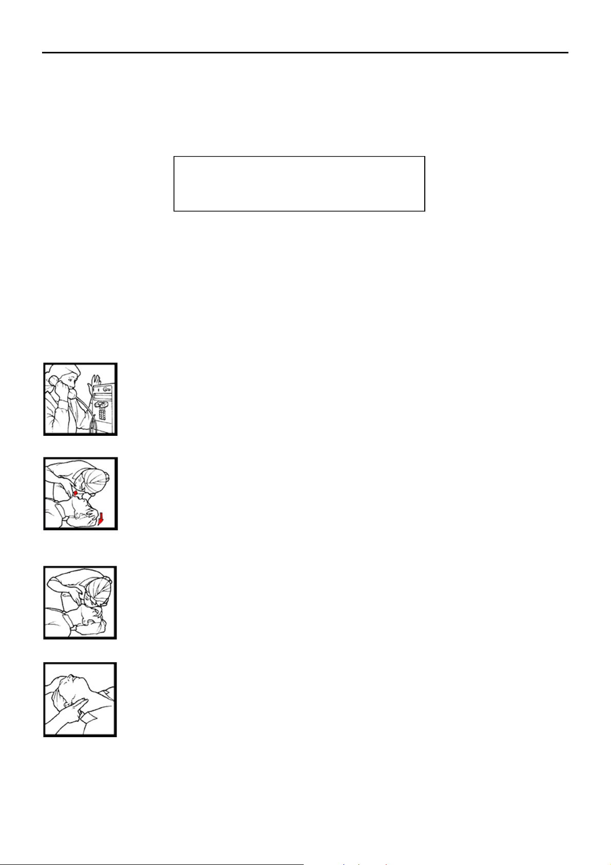
3.7 Emergency resuscitation technique
Step 1
Check the victim for unresponsiveness. If there is no response, immediately call for medical
assistance,andthen return to the person.
Step 2
Position the person flat on their back. Kneel by their side and place one hand on the forehead
and the other under the chin. Tilt the head back and lift the chin until teeth almost touch. Look
and listen for breathing.
Step 3
If not breathing normally, pinch the nose and cover the mouth with yours. Give two full breaths.
The person's chest will rise if you are giving enough air.
Step 4
Put the fingertips of your hand on the Adam's apple, slide them into the groove next to the
windpipe. Feel for a pulse. If you can notfeel a pulse or are unsure, move on to the next step.

TEM A07EXXXX – 1 Unit Transmitters Page 12
Step 5
Position your hands in the center of the chest between the nipples. Place one hand on top of the
other.
Step 6
Push down firmly two inches. Push on chest 15 times.
CONTINUE WITH TWO BREATHS AND 15 PUMPS UNTIL HELP ARRIVES.
3.7.1 Treatment for burns
Continue treat victim for electrical shock.
Check for points of entry and exit of current.
Cover burned surface with a clean dressing.
Remove all clothing from the injured area, but cut around any clothing that adheres to the skin and leave
it in place.
Keep the patientcovered, except the injured part, since there is a tendency to chill.
Splint all fractures.
(Violent muscle contractions caused by the electricity may result in fractures.)
Never permit burned surfaces to be in contact with each other, such as: areas between the fingers or
toes, the ears and the side of the head, the undersurface of the arm and the chest wall, the folds of the
groin, and similar places.
Transport to a medical facility
3.8 Electric safety precautions
All the parts making up the equipment have got danger identification tags (with a yellow background) to highlight
the parts dangerous for the operator that has access to the system.
Presence of hazardous energy levels
A hazardous energy level is defined as a stored energy level of 20 J or more, or
an available continuous power level of 240 VA or more, at a potential of 2 V or
more.
3.9 Electrostatic precautions
Before removing or replacing any PCB assembly within the equipment, make sure that all precautions comply
with ESD protections (ESD = Electro Static Discharge).
Make sure thatelectrostatic discharge protections are reset after maintenance and/or measurement operations.

TEM A07EXXXX – 1 Unit Transmitters Page 13
This ATTENTION tag is used for the majority of electronic devices that are
sensitive to electrostatic discharges.
If electronic parts have to be touched during installation or repair, please observe the following precautions.
Operators must be equipped with anti-static protection devices such as:
Elastic wrist band. To be fixed on the operator’s wrist.
Flexible cord. To be connected to the elastic wrist band and the special
plug on the shelf highlighted with the ESD warning label.
3.10 Waste electrical and electronic equipment (WEEE)
The purpose of the DIRECTIVE 2002/96/EC OF THE EUROPEAN PARLIAMENT
AND OF THE COUNCIL of 27 January 2003 on waste electrical and electronic
equipment ( WEEE ) is, as first priority, the prevention of waste electrical and
electronic equipment and, in addition, the reuse, recycling and other forms of
recovery of suchwastes so as to reduce the disposal of waste.
To do this, remember to collect separately all the electronic material.

TEM A07EXXXX – 1 Unit Transmitters Page 14
4ELECTRICAL SPECIFICATION
4.1 FREQUENCY - POWER
Frequency range-------------------------------------------------------------------------------------87.5 to 108.0MHz
Frequency setting------------------------------------------------------------------------------------------10 KHz steps
Internal setting mode--------------------------------------------------------------------------------------------by keys
External setting mode-------------------------- byOptional remote control ( GSM-TCP/IP-RS232-RS485 )
Frequency stability---------------------------------------------------------------------------------------- ±500Hz/year
Frequency generation--------------------------------------------------------------------------------- PLL synthesizer
Modulation type----------------------------------------------------------------direct VCO frequency modulation
Nominal frequency deviation --------------------------------------------------------------------------------- ±75KHz
RF output power ---------------------------------------------------0 to 10-20-50-100-200-250-300-400-500W
Power resolution setting ------------------------------------------------------------------------------------------1-5W
Power control stability------------------------------------------------------------------------------------------ < 0.2dB
Reverse output power control limit ----------------------------------------------------------------------- 1 to 30W
Harmonics emission---------------------------------------------------------------------------------------------<-70dBc
Spurious emission------------------------------------------------------------------------------------------------<-95dBc
Carrier reduction power ( carrier enable off )-------------------------------------------------------------->70dBc

TEM A07EXXXX – 1 Unit Transmitters Page 15
4.3 MODULATION CAPABILITY
MONO (left or right)------------------------------------------------------------------------------------30Hz to 15KHz
STEREO (by internal stereo generator OPT)------------------------------------------------------30Hz to 53KHz
MPX1 & MPX2 (opt) COMPOSITE (MONO or STEREO +RDS+ SCA)--------------------------30Hz to 75KHz
AES-EBU up to 192KHz or IP Audio (opt) ----------------------------------------------------------30Hz to 53KHz
SCA (opt) -------------------------------------------------------------------------------------------------30Hz to 100KHz
RDS Ext----------------------------------------------------------------------------------------------------30Hz to 100KHz
RDS Int (by internal RDS generator OPT) --------------------------------------------------------------------57KHz
4.4 CHARACTERISTICS IN MPX
Signal input --------------------------------------------------------------------------------------------MPX Unbalanced
Input impedance ---------------------------------------------------------------------------------------- 600or 10k
Input level-----------------------------------------------------0/+6/+12/dBm or Variable input level capability
Audio frequency response ( 50Hz to 57KHz) ---------------------------------------------------------------±0.5dB
Total HarmonicDistortion THD -------------------------------------------------------------------------------<0.02%
Signal to noise referred at deviation of 75KHz-------------------------------------------------------------->80dB
4.5 CHARACTERISTICS IN MONO
Signal input -------------------------------------------------------------------------------------------------Left or Right
Inputimpedance --------------------------------------------------------------------------600(balanced) or 10k
Unbalance rejection----------------------------------------------------------------------------------------------->40dB
Input level-----------------------------------------------------0/+6/+12/dBm or Variable input level capability
Pre-emphasis------------------------------------------------------------------------------------ std.50s ( opt 75uS )
Audio frequency response ( 50Hz to 15KHz) ---------------------------------------------------------------±0.5dB
Total HarmonicDistortion THD -------------------------------------------------------------------------------<0.02%
Signal to noise referred at deviation of 75KHz-------------------------------------------------------------->82dB

TEM A07EXXXX – 1 Unit Transmitters Page 16
4.6 CHARACTERISTICS IN STEREO
Signal inputs--------------------------------------------------------------------------------------------------Left &Right
Inputimpedance --------------------------------------------------------------------------600(balanced) or 10k
Unbalance rejection----------------------------------------------------------------------------------------------->40dB
Input level-----------------------------------------------------0/+6/+12/dBm or Variable input level capability
Pre-emphasis-------------------------------------------------------------------------------------std.50s ( opt 75uS )
Audio frequency response (30Hz to 15KHz)---------------------------------------------------------------<0.25dB
Cross-talk between left and right channel------------------------------------------------------------------->50dB
Total HarmonicDistortion THD -------------------------------------------------------------------------------- <0.1%
Signal to noise referred at deviation of 75KHz-------------------------------------------------------------->77dB
Suppression of 38KHz--------------------------------------------------------------------------------------------->70dB
Spurious suppression outside band ----------------------------------------------.in according to ETS 300-384
Pilot reference for RDS encoder (19 KHz out)-----------------------------------------------------------------1Vpp
4.7 SCA-Ext RDS CHARACTERISTICS
Input (SCA1) --------------------------------------------------------------------------------------------BNC unbalanced
Inputimpedance ----------------------------------------------------------------------------------------------------10K
Frequency response (50KHz to 100KHz)--------------------------------------------------------------------- ±0.2dB
Modulation capability------------------------------------------------------------------------------------------0 to 10%
4.8 REMOTE CONTROL
AUX I/O on DB15 TC-TS rear panel connector Interface---------------------------------------------------------
LAN on front panel ( OPT)-----------------------------------------------------TCP-IP Web-Server/SNMP/SMTP
RS485 on rear panel-------------------------------------------------------------------------------------------------------
Internal GSM Modem (OPT)----------------------------------------------------------------------------------------SMS

TEM A07EXXXX – 1 Unit Transmitters Page 17
4.9 POWER SUPPLY AND TEMPERATURE RANGE
Nominal Operating AC Mains Voltage --------------------------------------------------------------230VAC ±10%
AC Mains protection fuses ----------------------------------------------------------------------------2xT 8 AL 250V
50W Model Line Power-------------------------------------------------------<120VA @ 50W RF Output Power
100W Model Line Power --------------------------------------------------- <175VA @ 100W RF Output Power
300W Model Line Power --------------------------------------------------- <450VA @ 300W RF Output Power
500W Model Line Power --------------------------------------------------- <710VA @ 500W RF Output Power
Nominal temperature range------------------------------------------------------------------------------ -5° to 45°C
Operating temperature range -------------------------------------------------------------------------- -10° to 50°C
Storage temperature range------------------------------------------------------------------------------ -40° to 50°C
4.10 MECHANICAL SPECIFICATION
1 unit rack 19” ---------------------------------------------------------------------------------------485x44.4x545mm
10-20-50W model Weight -------------------------------------------------------------------------------------- <6.0Kg
100W model Weight --------------------------------------------------------------------------------------------- <7.5Kg
300W model Weight --------------------------------------------------------------------------------------------- <8.0Kg
500W model Weight --------------------------------------------------------------------------------------------- <8.0Kg

TEM A07EXXXX – 1 Unit Transmitters Page 18
4.11 INTERNAL MAIN MODULES
Exciter module------------------------------------------------------------------------------------------------13M7EXC1
Audio Connection Board Module ------------------------------------------------------------------------13M31640
FrontPanel Interface Module ---------------------------------------------------------------------------13M31800
RF 100-200-250 Module Amplifier-------------------------------------------------------------------- 13M3188B-C
RF 300-400-500W Module Amplifier------------------------------------------------------------------ 13M72387B
Power Supply Module for 500W Model-----------------------------------------------------13MPWRSP100048
Service Power Supply Module ----------------------------------------------------------------------13MPWRS7524
Current Meter Sensor Module ( only for 500W model) --------------------------------------------13M31810
Universal Current Meter Sensor Module (for all 1 Unit Rack TX models)----------------------13M32110
4.12 OPTIONS
Option A-----: Internal Stereo generator Module -----------------------------------------------------44C01180
Option B :--------Internal RDS Encoder--------------------------------------------------------------13M7MINIRDS
OptionC :------AES-EBU Digital Input Interface----------------------------------------------------13MAESEBU0
Option D : --- Automatic Frequency Deviation Control Card------------- -------------------------13M5804A
Option E :-------GSM by SMS Remote Control---------------------------------------------------------13KGSM05
Option F :----- TCP-IP Web Server/SNMP/SMTP Remote Control Card--------------------------13KTCPIP2
Option G : -- GSM & TCP-IP Web Server/SNMP/SMTP Remote Control Card------------------13KTCPIP3

TEM A07EXXXX – 1 Unit Transmitters Page 19
5Dichiarazione di Conformità UE
La presente dichiarazione di conformità è rilasciata sotto l'esclusiva responsabilità del fabbricante:
Produttore: Telecomunicazioni Elettroniche Milano Srl - Via Copernico, 11 - 20082 Binasco (MI)
Apparecchio radio Marca: TEM Trasmettitore VHF FM Modello A07E0501 – PotenzaRF 500W N°serie: VediEtichetta
applicata
Configurabile nei seguenti tagli di potenza da Software coni relativi codici
Codici A07E0501 A07E0401 A07E0301 A07E0251 A07E0201 A07E0101 A07E0051 A07E031 A070021 A07E0011
Potenza 500 W 400 W 300 W 250 W 200 W 100 W 50 W 30 W 20 W 10 W
Versione software: L.27.XX
“La potenza di uscita di ogni singolo apparato è certificata dalla presenza di uno dei suddetti codici sull’etichetta
apposta sull'apparato stesso e sulla presente Dichiarazione di Conformità.”
L'oggetto della dichiarazione è conforme alla pertinente normativa di armonizzazione dell'Unione:
Direttiva 2014/53/UE
Norma applicata Data Emesso da
EN 302 018 V2.1.1
EN 301 489-1 V1.9.2
EN 301 489-11 V1.3.1
EN 60215 Ed.1989 +A1:1992+A2:1994
29/11/18
26/11/14
26/11/14
04/02/15
TEM28/11/18
NEMKO N° 273431TRFEMC
NEMKO N° 273431TRFEMC
NEMKO N° 273431TRFSAF
Firmato a nome e per conto di (Signed for and on behalf of):
Luogo(Place): Binasco
Data (Date):29/11/18
Posizione (Position): Amministratore
Nome (Name): Antonio Fiordelisi
Firma (Signature):
L’immagine
rappresenta il modello A07E0501

TEM A07EXXXX – 1 Unit Transmitters Page 20
6EU Declaration of Conformity (DoC)
We,as producer,Telecomunicazioni Elettroniche Milano Srl - Via Copernico, 11 - 20082 Binasco (MI)
Declare that the DoC is issued under our sole responsibilityand belongs to the following product:
Radio Equipment Brand: TEM:Transmitter VHF FM ModelA07E0501 – RF Power 500W S/N: See Applied Label
RF power Sectable as by Software with following code
Code A07E0501 A07E0401 A07E0301 A07E0251 A07E0201 A07E0101 A07E0051 A07E031 A070021 A07E0011
Power 500 W 400 W 300 W 250 W 200 W 100 W 50 W 30 W 20 W 10 W
Firmware L.27.XX
"The output power of each individual is certified by the presence of one of the aforementioned codes on the label
affixed to the apparatus itself and to this Declaration of Conformity. "
The object of the declaration described above is in conformity with the relevant Union harmonisation legislation:
Directive 2014/53/UE RED
Standard Date From
EN 302 018 V2.1.1
EN 301 489-1 V1.9.2
EN 301 489-11 V1.3.1
EN 60215 Ed.1989 +A1:1992+A2:1994
29/11/18
26/11/14
26/11/14
04/02/15
TEM28/11/18
NEMKO N° 273431TRFEMC
NEMKO N° 273431TRFEMC
NEMKO N° 273431TRFSAF
Firmato a nome e per conto di (Signed for and on behalf of):
Luogo(Place): Binasco
Data (Date):29/11/18
Posizione (Position): Amministratore
Nome (Name): Antonio Fiordelisi
Firma (Signature):
The
Picture represent the A07E0501
Labe
l
This manual suits for next models
10
Table of contents
Popular Transmitter manuals by other brands


BWI Eagle
BWI Eagle AIR-EAGLE XLT 44-10100-120I-AC Product information bulletin

Conexx
Conexx Smart Transmitter user guide

Distech Controls
Distech Controls HS-RT Series Hardware installation guide

Evikon
Evikon PluraSens E2658-NH3-E user manual

Drivecon
Drivecon PWR Programming instructions

Erone
Erone SETR2641AM1 quick start guide


