Tempsens CALsys 1500 BB User manual

CALsys 1500 BB
CALsys 1500 BB
Black Body Temperature Calibrator
USER MANUAL

CONTENTS
1. General Instruction........................................................................1
1.1 Inform tion on oper ting instruction
1.2 Li bility & w rr nty
1.3 Unp cking & initi l inspection
2Before you start.............................................................................2
2.1 S fety inform tion
2.2 W rning
2.3 C ution
3 Tec nical Data................................................................................3
3.1 Technic l specific tion
3.2 Circuit di gr m
4 Overview........................................................................................4
4.1 Introduction
4.2 Outline description
5. Operating Instruction.....................................................................5
5.1 Power
5.2 Setting the temper ture
5.3 Oper ting Instruction
6. Operation of Controller...................................................................6
6.1 The Temper ture Controller
6.2 Altering the set point
6.3 Monitoring the Controlling St tus
6.4 Units
7. Maintenance & Trouble s ooting.....................................................7
7.1 M inten nce
7.2 Troubleshooting
8. Software Installation......................................................................8
8.1 Inst ll tion
8.2 P r meter in m in screen
1. Ge eral I structio
1.1 Information on operating instruction
Congr tul tions on your purch se of high-qu lity nd efficient CALsys 1500BB temper ture
c libr tor.Re d this m nu l c refully to ll instructions on s fety, oper tion nd m inten nce. It
serves s n import nt source of inform tion nd reference for inst ll tion nd oper tion of the
device. The gener l s fety requirements must be strictly dhered to when oper ting the
device. The f ct cont ined especi lly s fety re observed. If you experience ny further
questions, ple se cont ct our technic l support by phone or m il to tech@tempsens.com
1.2 Liability and warranty
This instrument h s been m nuf ctured to ex cting st nd rds nd is w rr nted for twelve
months g inst electric l bre kdown or mech nic l f ilure c used through defective m teri l or
workm nship, provided the f ilure is not the result of misuse. In the event of f ilure covered
by this w rr nty, the instrument must be returned, c rri ge p id, to the supplier for
ex min tion nd will be repl ced or rep ired t our option.
INTER F ER E N C E WI T H O R F A I L U R E T O P R O P E R L Y M A I N T A I N T H I S I N S T R U M E N T M A Y
INV AL I D T H I S W A R R A N T Y .
1.3 Unpacking & Initial Inspection
Our p cking dep rtment uses custom designed p ck ging to send out your unit, but s
ccidents c n still h ppen in tr nsit, you re dvised, fter unp cking the unit, to inspect it for
ny sign of d m ge, nd confirm th t your delivery is in ccord nce with the p cking note. If
you find ny d m ge or find ny p rt missing during delivery notify us nd the c rrier
immedi tely. If the unit is d m ged you should keep the p cking for possible insur nce
ssessment.
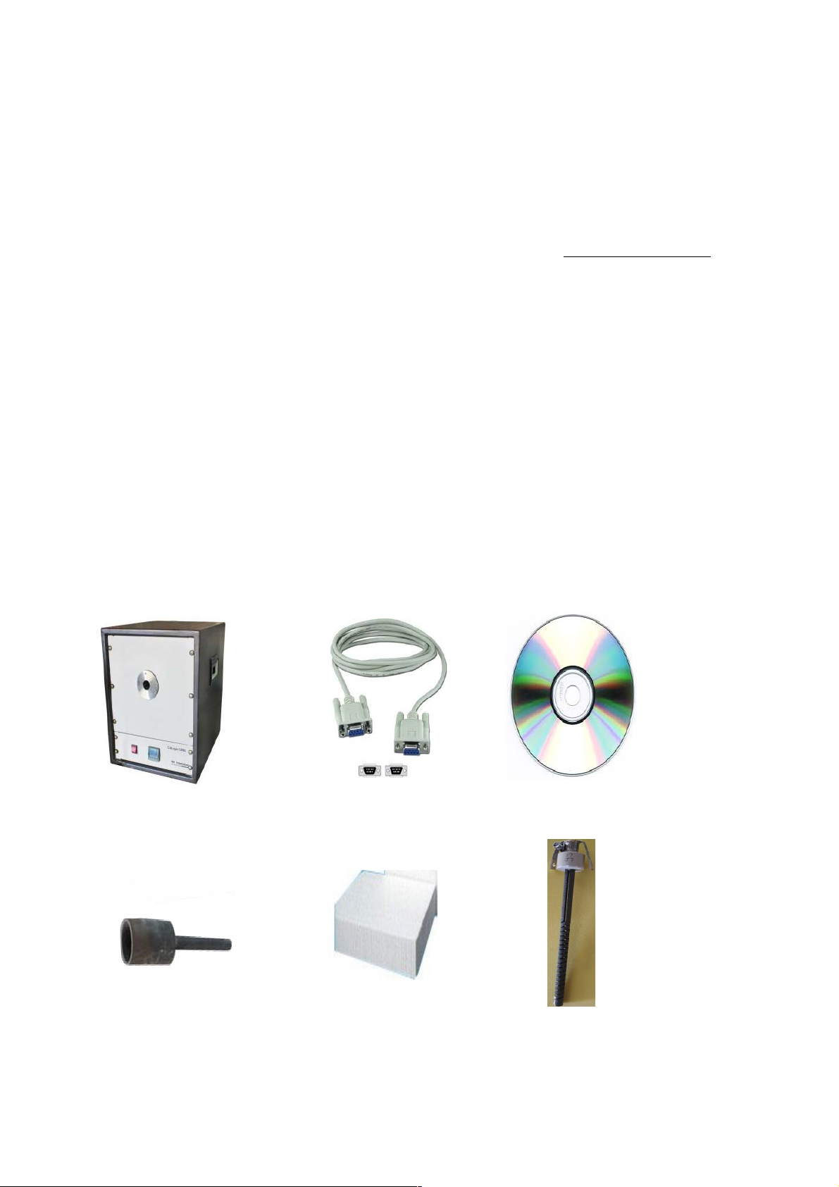
After unp c k in g you will find following items.
C lsys 1500 BB RS- 23 2 c ble Softw re C D
Silicon C r bi de C vity Insul tion wool 6 N OS.He ters

2. Before you Start
2.1 Safety Information
Use the instrument only s specified in this m nu l. Otherwise, the protection provided by the
instrument m y be imp ired. Refer to the s fety inform tion below nd throughout the m nu l.
The following definitions pply to the terms “W rning” nd “C ution”.
“W rning” identifies conditions nd ctions th t m y pose h z rds to the user.
“C u tio n ” i dentifies conditions nd c ti o ns th t m y d m ge the instrument
being used.
[!] Warning: T e furnace is only to be used as described in t is
manual. It is recommended t at you only use accessories provided by
t e manufacturer.
2.2 Warning
To void possible electric shock or person l injury, follow these guidelines.
This equipment must be correctly e rthed.
A protective e rth is used to ensure the conductive p rts c n not become live in the event of
f ilure of the insul tion.
The protective conductor of the flexible m ins c ble which is colored green/yellow MUST be
connected to suit ble e rth.
W rning: Intern l m ins volt ge h z rd. Do not remove the p nels.
There re no user service ble p rts inside. Cont ct us for rep ir.
Do not use the pp r tus outside its recommended r nge i.e., + 500 to 1500° C.
Ensure infl mm ble m teri ls, re kept w y from hot p rts of the pp r tus, to prevent
fire risk.
Before connecting to the electricity supply, ple se f mili rize yourself with the p rts of the
c libr tor with the help of oper ting m nu l.
BURN HAZARD – Do not touch the t rget surf ce of the unit.
Alw ys repl ce the fuse with one of the s me r ting, volt ge nd type.
Overhe d cle r nce is required. Do not pl ce unit under c binet or other structure.
Do not use this unit for ny pplic tion other th n c libr tion work.
Completely un ttended high te m pe r t u r e oper tion is no t r e c o mmended for
s fety re sons.
CALIBRAT ION EQUIPEMENT should only be used by TRAINED PERSONNEL.
We r ppropri te protective clothing.
2.3 Caution
To void possible d m ge to the instrument, follow these guidelines.

Components nd he ter lifetime c n be shortened by continuous high temper ture
oper tion.
Do not c h nge the v lues o f the c li br tion const nts fr o m the f c tory se t
v lues. The co rr e c t setting of the s e p r me te r s is import nt to the s f e t y
nd proper o per tio n o f the c l i br tor.
3. Tech ical Data
3.1 Tec nical Specification
Volt ge 230 V AC
Power M ximum
Supply Frequency 50/60 Hz
Temper ture r nge 500 to 1500°C
Resolution 1.0 °C
St bility ± 1.0 °C
Controlling sensor R type T/C
Time to re ch m x. Temper ture 2.5 hours
Oper ting Temper ture 20 to 45 °C
Controller Specific tions Eurotherm 3216 Series
Over temper ture protection Autonics controller with R Type T/C
St biliz tion Time 15 to 20 Min.
Dimensions 590(H) x 450(W) x 530(D) mm
R di tion c vity type & Dimension Silicon Carbide,46 mm Dia x 85mm depth
Extern l Aperture 40 MM
Weight Approx 50 kg
3.2Circuit Diagram

P: PHASE= RED WIRE
N: NEUTRAL = BLACK WIRE
E: EARTH =BLUE WIRE
4. Overview
4.1 Introduction:
The ‘CALsys 1500BB’ provides st ble temper ture source for l bor tory c libr tion of
r di tion thermometers by comp rison method up to temper ture r nge of 1500°C.
The ‘CALsys 1500BB’ model h s been designed in single p rt. This model provides n
isotherm l enclosure in which the Non cont ct pyrometers c n be checked g inst the
temper ture of the bl ck body. For tr ce ble c libr tion m ster pyrometer should be used.
The units’ fe tures emissivity of 0.99, thus offering the closest pproxim tion of t rget
surf ce th t is perfect emitter of infr red energy.
The ‘CALsys’ models re p rt of wide r nge of c libr tors designed nd m de by us. Ple se
cont ct us in c se you require more inform tion bout our other pro-ducts.
DANGER! Power is present even if t e front panel circuit breaker is in t e OFF (0)
position.
4.2 Outline Description:
‘C lsys 1500BB is tr nsport ble unit designed for use on ny re son ble fl t surf ce. The
t rget is ridged luminum pl te which is p inted by high emissive p int .The t rget is
he ted by Silicon Carbide Spiral Rod Heater which llows the source to he t up to 1500°C in
bout 2.5 Hrs nd hold it st ble t temper ture within ±1.0°C. The he ter blockhouses consists
he ter & the controller sensor. The temper ture controller to sense the block temper ture
uses this sensor. To obt in the m int in required temper ture the controller v ries the power
to the he ters vi solid-st te rel y.
[!]Warning: Do not insert impure materials, metal objects or probes etc. into t e
block.
4.3 INSTALLATION OF CALSYS 1500BB
Unpack t e furnace carefully and inspect it for any
damage t at may ave occurred during s ipment.
If t ere is s ipping damage, notify t e carrier
immediately.

Silicon Carbide Cavity
Insert the he ters in to the groves of SS ch mber s
per specified s me sr. no. On he ter holder nd
ch mber.
NOTE: HEATERS INSERT VERY CAREFULLY.
After Inserting its tig t by screwdriver
Open b ck p nel sheet of CALsys 1500 nd
remove all Packing s eet from inside.
Insert t e 6 nos. silicon eater at back side
of t e inner c amber. As s own in below
image.

connect t e P ase and Netural wire as per given picture.
Ope holdi g ceramic clamp as show i figure.
Ope the fro t plate of CALsys 1500BB a d remove
all packi g sheets from i side.
Fix t e 6 eater into t e c amber and
Connect all t e aluminum strip in
series.
Heating Element connection.

fix t e front plate of calsys 1500BB
Fully assembled of CALsys 1500BB
I sert cavity a d e sure that the tail of cavity fix to the
groove o the back pa el.
A d make sure cavity properly i sert at back pa el hole
as show i image.
After insert the cavity tight the holding cap of SS
chamber by screw driver as per shown picture.
After completed holding clamp its look like this.

5. Operati g I structio
(1) PID Controller
(2) ON/OFF switch of controller
(3) Power C ble
(4) RS-232
(5) MCB (for He ter)
(6) S fety controller for over he ting temper ture.
(7) 1."R" type thermocouple Duplex for controlling nd
over temper ture protection.
Inner ch mber of c lsys 1500BB
5.1 Power
Plug the bl ck body power cord into m ins outlet of the proper volt ge, frequency nd current
c p bility. Typic lly this will be (230 VAC±10%, 50-60 Hz). Turn on the bl ck body using "M ins"
switch lo c ted t re r side. The bl ck body will turn on nd begin to he t for previously
progr mmed set point.
5.2 Setting t e Temperature Press “UP” or “DOWN” buttons to ch nge the ch nge the
temper ture set-point v lue. When the set-point temper ture is ch nged the controller

will switch the CALsys 1500BB ON or OFF to r ise or lower the temper ture. The
displ yed temper ture will gr du lly ch nge until it re ches the setpoint temper ture.
The temper ture b th requires 15 to 20 minutes to re ch the set-point depending on the
sp n. Another 10 to 15 minutes is required to st bilize the temper ture b th within ±
1.0ºC of the set-point.
5.3 Operating Instruction:-
1. fter the completly inst ll tion.
2. Connect the ‘CALsys 1500BB’ to suit ble power supply. ON the M ins switch loc ted t b ck
side with power entry.
3. set the desire temper ture v lue in PID by using UP & Down key.
4. Aim the reference (M ster) st nd rd infr red temper ture sensor to the t rget re .
5. PV (Present v lue) displ y in controller will gr du lly rise until it re ches the set point
temper ture. The controller t kes some times to re ch the set-point depending on the sp n.
Furn ce is st ble when PV is equ l to SV (Set V lue).
6. M ster sensor t ke some times to re ch the setpoint temper ture nd st ble t temper ture
ne r bout controller set temper ture.
7. When temper ture of the m ster nd UUC (Unit under c libr tion) re st ble record the
re dings of m ster sensor.
8. Comp re the UUC re ding with the m ster’s re ding & find out the error by comp rison method.
9. Reset the controller nd / or repe t the c libr tion for nother c libr tion point or for nother
sensor.
10. When the c libr tion is complete, reset the controller to 0°C & w it until the unit h s cooled to
below 100°C, before moving the ‘CALsys 1500BB to new loc tion the ‘CALsys 1500BB’ must be
cooled below 100°C before it c n be put b ck into its c rrying c se.
11. NOTE: Alw ys use reference IR thermometer for comp rison c libr tion method.
Note:
All other controller p r meters re comp ny set nd locked. It is
recommended not to ch nge them.
When the source is oper ted t ny temper ture bove mbient,
the front f ce nd pl te become hot. UP
Key
Dow
Key
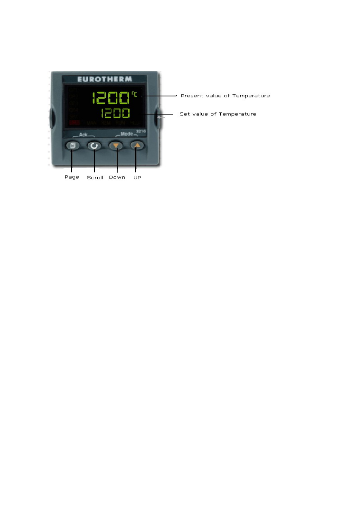
6. Operatio of Co troller
FRONT PANEL LAYOUT
Operator Butto s
6.1 T e Temperature Controller
The controller h s du l displ y, the upper displ y indic tes the me sured temper ture, nd
the lower displ y indic tes the desired temper ture or set point.
6.2 Altering t e Set point
To ch nge the set point of the controller use the UP nd DOWN keys to r ise nd lower the set
point to the required v lue. The lower displ y ch nges to indic te the new set point.
6.3 Monitoring t e Controller Status
A row indic te the controllers st tus s follows
OP1 He t Output
REM This be con indic tes ctivity on the PC interf ce
ALM this indic tes when PV (Present v lue) is more th n 1500°C.
6.4 Units
Moment ry pressing of the Scroll key will show the controller units °C or °F by using SCROLL
key & UP & DOWN key unit c n be ch nge.
IMPORTANT NOTICE
T e controller's function settings are preset and will not require adjustment. Use
only up & down key.

7. Mai te a ce & Trouble shooti g
7.1 Maintenance
The c libr tion instrument h s been designed with the utmost c re. E se of oper tion nd simplicity
of m inten nce h ve been centr l theme in the product development. Therefore, with proper c re
the instrument should require very little m inten nce. Avoid oper ting the instrument in n oily,
wet, dirty, or dusty environment.
If the outside of the instrument becomes soiled, it m y be wiped cle n with d mp cloth nd mild
detergent. Do not use h rsh chemic ls on the surf ce which m y d m ge the p int.
Avoid knocking or dropping the c libr tor.
If the m ins supply cord becomes d m ged, repl ce it with cord with the ppropri te g uge wire
for the current of the instrument.
Depending on the environment in which it is used, periodic cle ning is recommended. Cle ning m y
be ccomplished by the use of sm ll dry p int brush.
7.2 Trouble s ooting
1. Unit fails to operate
Check fuse if it is tripped switch is ON. If not power ON of c lsys 1500 BB consult us.
2. Unit unstable
Controller p r meter h s been interfered, consult us.
3. If t e temperature of t e calibrator is not rising
( ) The he ting element m y be open.
(b) The thermocouple m y be open.
(c) The SSR m y be d m ged.
(d) The controller m y not be giving output
(e) The mbient temper ture inside the ch mber is r ised nd s fety controller switched
OFF the power
CAUTIONARY NOTE
TEMPSENS PRODUCTS ARE INTENDED FOR USE BY TECHNICALLY TRAINED AND COMPETENT
PERSONNEL FAMILIAR WITH GOOD MEASUREMENT PRACTICES.
IT IS EXPECTED THAT PERSONNEL USING THIS EQUIPMENT WILL BE COMPETENT WITH THE
MANAGEMENT OF APPARATUS WHICH MAY BE POWERED OR UNDER EXTREMES OF
TEMPERATURE, AND ARE ABLE TO APPRECIATE THE HAZARDS WHICH MAY BE ASSOCIATED
WITH, AND THE PRECAUTIONS TO BE TAKEN WITH, SUCH EQUIPMENT.

8. Software Installation
The provided Tempsens softw re offers possibilities toconnect furn ce temper ture b th nd
ch nge set point,m ximum time sp n, view re l time gr ph ndev lu te me suring d t .
1.1 Installation
Inst ll the c libr tion softw re using the inst ll tion guide file on CD ROM. After inst ll tion of
the softw re; Double click the pplic tion. It willopen the screen of softw re.
1.2 Parameter in mainscreen
1.2.1 Communication
Communic tion between the furn ce nd the softw re is implemented vi RS-232 c ble
connected between the furn ce nd the PC seri l port. This en bles the cquisition nd
recording of d t , s well s the tr nsfer of comm nds from the softw re pplic tion to the
tempsens furn ce. Communic tion c n be done by clicking on connect nd select correct COM
port ddress (fig. 1) where furn ce is connected. Also user h s to select type of controller
version3216 (fig. 2). Then click on CONNECT button. Shown com2 connected successfully.

1.2.2 Scale Trend: -in sc le trend you h ve to ch nge the Y-Axis Min v lue 0 nd Y-AxisM x
v lue 1500.M ximumTime Sp n, Minutes h ve to s ve d t the d t logging up to 120
minutes, th n clickon st rt gr ph button. After complete the t sk clickon s ve to file button.
Set Point (°C): - in which you c n set temper ture of furn ce s your requirement.
PVI Value: - Re d the current PVv lue (present v lue of furn ce temper ture).
File will be stored in .xls form tto s ve previous recordopen the file by clicking on menu file
open.

Safety i structio s:
Do's a d do 'ts -
Keep swich off the power supply fter swich off the furn ce MCB.
Don't touch surf ce ch mber during furn ce is ON c uses over he ting injury.
Don't remove power plug during furn ce is ON.
Keep swich off red button t front of furn ce fter use.
Keep down the furn ce temper ture t mbient fter use then switch off the furn ce.
After open the furn ce keep pl ce c vity nd furn ce p rts s fely.
Don't open the furn ce ch mber during furn ce is ON.
In c se of ny trouble ple se cont ct our cont ct person.
I formatio
Packing Instruction
To tr nsport or store the instrument, ple se use the origin l box or box p dded with
sufficient shock bsorbing m teri l. For stor ge in humid re s or shipment overse s, the
device should be pl ced in welded foil ( ide lly long with silicon gel) to protect it from
humidity.
Warranty
TEMPSENS CALsys 1500BB instrument h ve w rr nty of one ye r from the invoice d te. This
w rr nty covers m nuf cturing defects. User induced f ults re not covered under this
w rr nty.
Limit of Li bility
TEMPSENS not li ble for ny d m ges th t rise from the use of ny ex mples or processes
mentioned in this
Specifications are subject to c ange wit out notice
Copyright:@ 2009, TEMPSENS. All right
This document m y cont in propriet ry inform tion nd sh ll be respected s
propriet ry document to TEMPSENS with permission for review nd us ge given only to the rightful
owner of the equipment with which this document is ssoci ted.
TEMPSENS reserves the right to m ke ch nges, without further notice, to ny product
herein to improve reli bility, function, or design . TEMPSENS does not ssume ny li bility rising out of
the pplic tion or use of ny product described herein, neither does it convey ny license under its p tent
right nor the right of others.
Copyright:@2009

Table of contents
Other Tempsens Measuring Instrument manuals

Tempsens
Tempsens CALsys 1500 User manual

Tempsens
Tempsens CALSYS 650 User manual

Tempsens
Tempsens CALsys-15/110 Autocal User manual

Tempsens
Tempsens CALsys 250 User manual

Tempsens
Tempsens CALsys 1200 User manual

Tempsens
Tempsens CALsys 1500 L User manual

Tempsens
Tempsens CALsys 1700 User manual

Tempsens
Tempsens CALsys -35/200 User manual
Popular Measuring Instrument manuals by other brands


Naneos
Naneos Partector Operation manual

Status Instruments
Status Instruments DM3600U manual

gaskatel
gaskatel Mini-HydroFlex 81020 operating instructions

Mitsubishi Electric
Mitsubishi Electric ME96-SSE-MB user manual

Gardner Bender
Gardner Bender PM3000 operating instructions

Gemlogis
Gemlogis MANTIS quick start guide