Tempsens CALsys 1700 User manual

CALsys 1700
USER MANUAL
Temperature Calibrator
TEMPSENS INSTRUMENTS (l) PVT. LTD. U#ll
Thermal & Cable Solutions

1. General Instruction............................................................................................... 2
1.1 Information on operating instruction
1.2 Liability & warranty
1.3 Unpacking & initial inspection
2 Before you start.................................................................................................... 3
2.1 Safety information
2.2 Warning
2.3 Caution
3 Technical Data....................................................................................................... 4
3.1 Technical specification
3.2 Circuit diagram
4 Overview................................................................................................................ 5
4.1 Introduction
4.2 Outline description
5 Operating Instruction........................................................................................... 9
5.1 Power
5.2 Setting the temperature
5.3 Operating Instruction
6. Operation of Controller........................................................................................ 10
6.1 The Temperature Controller
6.2 Altering the set point
6.3 Monitoring the Controlling Status
6.4 Units
7 Maintenance & Trouble shooting........................................................................ 11
7.1 Maintenance
7.2 Troubleshooting
8 Software Installation........................................................................................... 12
8.1 Installation
8.2 Parameter in main screen
9 Safety Instruction................................................................................................ 14
Content

1.1 Information on operating instruction
Congratulations on your purchase of high-quality and efficient CALsys 1700 temperature calibrator.Read this
manual carefully to all instructions on safety, operation and maintenance. It serves as an important source of
information and reference for installation and operation of the device. The general safety requirements must be
strictly adhered to when operating the device. The fact contained especially safety are observed. If you experience
any further questions, please contact our technical support by phone or mail to
1.2 Liability and warranty
This instrument has been manufactured to exacting standards and is warranted for twelve months against electrical
breakdown or mechanical failure caused through defective material or workmanship, provided the failure is not the
result of misuse. In the event of failure covered by this warranty, the instrument must be returned, carriage paid, to
the supplier for examination and will be replaced or repaired at our option.
INTERFERENCE WITH OR FAILURE TO PROPERLY MAINTAIN THIS INSTRUMENT MAY INVALID THIS
WARRANTY.
1.3 Unpacking & Initial Inspection
Our packing department uses custom designed packaging to send out your unit, but as accidents can still happen in
transit, you are advised, after unpacking the unit, to inspect it for any sign of damage, and confirm that your delivery
is in accordance with the packing note. If you find any damage or find any part missing during delivery notify us and
the carrier immediately. If the unit is damaged you should keep the packing for possible insurance assessment.
After unpacking you will find following items.
Phone No.
0294-3052959
2
1. General Instruction
Calsys 1700 Heaters 4 Nos Software CD
Rs-232
B Type T/C Ceramic Block for Dry Block Ceramic Cavity for Black Body

3
2.1 Safety Information
Use the instrument only as specified in this manual. Otherwise, the protection provided by the instrument may be
impaired. Refer to the safety information below and throughout the manual.
The following definitions apply to the terms “Warning” and “Caution”.
Ÿ“Warning” identifies conditions and actions that may pose hazards to the user.
Ÿ“Caution” identifies conditions and actions that may damage the instrument being used.
2.2 Warning
To avoid possible electric shock or personal injury, follow these guidelines.
ŸThis equipment must be correctly earthed.
ŸA protective earth is used to ensure the conductive parts can not become live in the event of a failure of the
insulation.
ŸThe protective conductor of the flexible mains cable which is colored green/yellow MUST be connected to a
suitable earth.
ŸWarning: Internal mains voltage hazard. Do not remove the panels.
ŸThere are no user serviceable parts inside. Contact us for repair.
ŸDo not use the apparatus outside its recommended range i.e., + 500 to 1700° C.
ŸEnsure inflammable materials, are kept away from hot parts of the apparatus, to prevent fire risk.
ŸBefore connecting to the electricity supply, please familiarize yourself with the parts of the calibrator with the
help of operating manual.
ŸBurn Hazard – Do not touch the target surface of the unit.
ŸAlways replace the fuse with one of the same rating, voltage and type.
ŸOverhead clearance is required. Do not place unit under a cabinet or other structure.
ŸDo not use this unit for any application other than calibration work.
ŸCompletely unattended high temperature operation is not recommended for safety reasons.
ŸCalibration Equipment should only be used by Trained Personnel.
ŸWear appropriate protective clothing.
2.3 Caution
To avoid possible damage to the instrument, follow these guidelines.
ŸComponents and heater lifetime can be shortened by continuous high temperature operation.
ŸDo not change the values of the calibration constants from the factory set values. The correct setting of these
parameters is important to the safety and proper operation of the calibrator.
[!] Warning :
DANGER !
The blackbody is only to be used as described in this manual. It is recommended that you only
use accessories provided by the manufacturer.
Power is present even if the front panel circuit breaker is in the OFF (0) position.
2. Before You Start

3.1 Technical Specification
Voltage : 230 V AC
Power : 3kw
Supply Frequency : 50/60 Hz
Temperature Range : 500 to 1700°C
Resolution : 0.1 °C
Stability : ± 2.0 °C
Controlling Sensor : B type T/C Duplex
Time to reach Max. Temperature : 3 hours
Operating Temperature : 20 to 45 °C
Controller Specifications : Eurotherm P104 series
Over temperature Protection : Autonics safety controller with B Type T/C
Stabilization Time : 15 to 20 Min.
Dimensions : 640(H) x 500(W) x 550(D) mm
Block/Cavity Aperture : 2X6.5, 2x8.5 mm with 140mm depth/Ceremic 29MM dia end
closed tube
Weight : Approx 80 kg
4
3. Technical Data
3.2 Circuit Diagram
N
P
E
R
F
Fan 230V AC
Transformer
Heater
B Type T/C
P: PHASE= RED WIRE
N: NEUTRAL = BLACK WIRE
E: EARTH =BLUE WIRE
N
P
MCB
ROCKER
SWITCH
Controller
Thyristor
1
2
3
4
56
P N
V+
V-
+
-
1A
1B
Communication Cable
RS-485
Convertor
Contector
N
P
Fuse
SF
RS-232

5
4.1 Introduction
The CALsys 1700 used as Dry block calibrator for thermocouple calibration and it can be used also as a pyrometer
calibration with ceramic cavity.
The 'CALsys 1700' has been designed to provide stable and accurate temperature to enable professionals to
calibrate Temperature Sensing Devices (Thermocouple & pyrometer) by comparison method up to a temperature
range of 1700°C. The 'CALsys 1700L' model has been designed to be rugged and easily maintained. This model
provides an isothermal enclosure (Ceramic block) in which the thermocouple can be calibrated against the
temperature of the calibrator.
The 'CALsys 1700BB' model has been designed in single part. This model provides an isothermal enclosure in
which the Non contact pyrometers can be checked against the temperature of the black body. For traceable
calibration a master pyrometer should be used. The units' features emissivity of 0.99, thus offering the closest
approximation of a target surface that is a perfect emitter of infrared energy.
4.2 Outline Description
'Calsys 1700 is a transportable unit designed for use on any reasonable flat surface. The target is a ridged Ceramic
Tube Cavity which is painted by a high emissive paint .The target is heated by MoSiO2 heaters which allows the
source to heat up to 1700°C in about 3Hrs and hold it stable at temperature within ±2.0°C. The heater blockhouses
consists a heater & the controller sensor. The temperature controller to sense the block temperature uses this
sensor. To obtain the maintain a required temperature the controller varies the power to the heaters via a power
control device.
[!] Warning : Do not insert impure materials, metal objects or probes etc. into the cavity.
4. Overview
Ceramic Block for 1700L Ceramic
Cavity for 1700BB
NOTE:
1. Ceramic block and ceramic cavity should be
removing at ambient temperature.
2. Use at a time block or ceramic cavity ( Not use both at
a time)
3. Fumes will appear initially for 3-4 times of CALsys
1700 operation.
4. Insertion of Ceramic cavity and ceramic block should
be such that it matches face to Face of inner SS
chamber for proper calibration.
4.3 Parts Details
(3) Strips of heating
element : This are aluminum
braided strips which are used
for making Series
connection.
(1) CALsys 1700 Housing :
This is the powder coated box
of CRCA
(2) Heating Chamber : This is
a SS chamber having ceramic
fiber board Insulation.
(4) Molybdenum di-silicate
heating element : The Moly-
D element is dense cermets
material consisting of
molybdenum di-silicate
(MoSi2) and glassy phase
silicon dioxide (SiO2).

6
(5) Element Mounting Metallic Holder : The Moly-D elements are hung vertically
and must be supported by the cold ends. This Metallic holder is used for same
purpose.
(6) All Accessories
RS-232 Cable
Cavity
Block
Sensor
Blots
Heating
Element
Wool
Hording Clamp Strips
(7) RS-232 cable : It is used for connect the controller to the PC. I tools (Download
from Eurotherm website) software is used for communicate the controller to PC and
CAL soft for graphical view and data logging of the CALsys 1700.
(8) Controlling Sensor Connection : Connect thermocouple wire to the controller terminal according to polarity.
(There is difference between main controller and safety controller reading, is not configured by others.)
Main Controller T/C Connection (1A+)
Connect at V+ & (1B-) Connect at V-
Safety Controller T/C Connection
(2A+) connect at 5 & (2B-) connect at 6

7
4.4 Installation of Calsys 1700
1) Unpack the furnace carefully
and inspect it for any damage
that may have occurred during
shipment. If there is shipping
damage, notify the carrier
immediately.
2) Open the front plate and back
sheet of CALsys 1700 and
remove all packing sheets from
inside.
3) Heating chamber of CALsys
1700.
4) heaters are inserted in holding clamp and then
heaters with clamp are inserted in heating
chamber.
holding clamp inserting in heaters holding clamp with heaters tight
with screw
Insert heaters in insulation board
as shown in figure (ceremic board)
Note : Heaters are very
fragile so please
assemble very - very
carefully and do not
apply more force on
heater and other
element but connection
should not be loosed.
5) Insertion of heating element in ceremic board.
Measure the height should be around 40mm from
insulation board.
Insertion of heating element 40 mm height after inserting
heating element
After insertion of heaters
Note : Heaters are very
fragile so please
assemble very- very
carefully and do not
apply more force on
heater and other
element but connection
should not be loosed.
6) After fixed all heaters connects the connection strips
(through nut and bolt with spanner). All four heaters
connected in series connection.
Connection strips connect
with heater
Connection strips connect in pair
of 3 heaters
remaining 2 heaters connect
individual strip
Note : The inner
chamber include open
connection strip placed
back side of main outer
body of furnace for
proper connection.

8
7) After connecting strips cover
ceramic board with insulation
wool for prevention heat loses.
8) Insert the Controlling Sensor in chamber till it
doesn't touch the ceramic tube. Controlling Sensor is
very fragile please insert it very carefully.Sensor
sholud be touch the ceramic tube otherwise deviation
will occur.
Insert controlling sensor here Insert sensor in the hole carefully
tight bolt with screw driver
Note : remember that
after inserting B type
sensor screw should
not be very tight and
sensor not insert before
insertion of heating
element otherwise
sensor will be damage.
9) After above all steps complete. The inner chamber
is Ready for installation in outer cabinate.
The inner chamber insert carefully from front side and
after this all four nut bolt tight shown as below.
fix the ss chamber into
outer cabinate
nut bolt tight
12) After this the transformer lead connect (through
nut and bolt with the help of spanner) in the open strip
from back side as per shown in Figure.
cable connect
with right open
strip in back side
cable connect
with left open
strip in back
side
13) Screw tight the cable with the strips . As shown in
figure.
10) Check the ss chamber proper fit in the outer
chamber.
14) After all Connection (Not Loose also not too much
given force to terminals ) the Back View of furnace is
Look As below.
Note : Once you heated 3-4 times then recheck all
heater connection of CALsys 1700 (there are no any
loose connection) to avoid any drops of voltage.
Re-fix the front panel and back with help of bolts
11) Connect B type sensor M & S terminal with safety
controller as shown in the Figure.
Sensor M Terminal
Sensor S Terminal

9
5. Operating Instruction
1
2
3 4 5 6
(6.1)"B" type duplex thermocouple
for controlling & over temperature
protection.
5.1 Power
Plug the black body power cord into a mains outlet of the proper voltage, frequency and current capability. Typically
this will be (230 VAC±10%, 50-60 Hz). Turn on the black body using "Mains" switch loacated at rear side. The black
body will turn on and begin to heat for previously programmed set point.
Note:
ŸAll other controller parameters are company set and locked. It is recommended not to change them.
ŸWhen the source is operated at any temperature above ambient, the front face and plate become hot.
5.2 Setting the Temperature
Press “UP” or “DOWN” buttons to change the change the temperature set-point value. When the set-point
temperature is changed the controller will switch the CALsys 1700 ON or OFF to raise or lower the temperature. The
displayed temperature will gradually change until it reaches the setpoint temperature. The temperature bath
requires 15 to 20 minutes to reach the set-point depending on the span. Another 10 to 15 minutes is required to
stabilize the temperature bath within ± 2.0ºC of the set-point.
[!] Warning : Do not connect or disconnect while power is on. Do not disconnect power when blackbody is
hot and fans are running.
5.3 Operating Instruction
ŸAfter the completely installation.
ŸConnect the 'CALsys 1700' to a suitable power supply. ON the Mains switch located at back side with power
entry.
ŸSet the desire temperature value in PID by using UP & Down key.
ŸAim the reference (Master) standard infrared temperature sensor to the target area.
ŸPV (Present value) display in controller will gradually rise until it reaches the set point temperature. The
controller takes some times to reach the set-point depending on the span. Furnace is stable when PV is equal to
SV (Set Value).
ŸMaster sensor take some times to reach the set point temperature and stable at temperature near about
controller set temperature.
ŸWhen temperature of the master and UUC (Unit under calibration) are stable record the readings of master
sensor.
ŸCompare the UUC reading with the master's reading & find out the error by comparison method.
ŸReset the controller and / or repeat the calibration for another calibration point or for another sensor.
ŸWhen the calibration is complete, reset the controller to 0°C & wait until the unit has cooled to below 100°C,
before moving the 'CALsys 1700 to new location the 'CALsys 1700' must be cooled below 100°C before it can
be put back into its carrying case.
ŸNOTE : Always use a reference IR thermometer for comparison calibration method.3
[!] Warning : Do not exceed the maximum temperature above 1700°C.
3. RS-232
4. Power Cable
5. MCB (for Heater)
6. FAN (Safety controller for over heating temperature.)
1. ON/OFF Switch
2. PID Controller

10
6. Operation of Controller
6.1 The Temperature Controller
The controller has a dual display, the upper display indicates the measured temperature, and the lower display
indicates the desired temperature or set point.
6.2 Altering the Set point
To change the set point of the controller use the UP and DOWN keys to raise and lower the set point to the required
value. The lower display changes to indicate the new set point.
6.3 Monitoring the Controller Status
A row indicate the controllers status as follows
OP1 Heat Output
REM This beacon indicates activity on the PC interface
ALM this indicates when PV (Present value) is more than 1700°C.
6.4 Units
Momentary pressing of the Scroll key will show the controller units °C or °F by using SCROLL key & UP & DOWN key
unit can be change.
IMPORTANT NOTICE
The controller's function settings are preset and will not require adjustment. Use only up & down key.
Front Panel Layout
Page Down UP Enter
Preset value of temperature
Set value of temperature

11
7. Maintenance & Trouble shooting
7.1 Maintenance
ŸThe calibration instrument has been designed with the utmost care. Ease of operation and simplicity of
maintenance have been a central theme in the product development. Therefore, with proper care the
instrument should require very little maintenance. Avoid operating the instrument in an oily, wet, dirty, or dusty
environment.
ŸIf the outside of the instrument becomes soiled, it may be wiped clean with a damp cloth and mild detergent. Do
not use harsh chemicals on the surface which may damage the paint.
ŸAvoid knocking or dropping the calibrator.
ŸIf the mains supply cord becomes damaged, replace it with a cord with the appropriate gauge wire for the
current of the instrument.
ŸDepending on the environment in which it is used, periodic cleaning is recommended. Cleaning may be
accomplished by the use of a small dry paint brush.
7.2 Trouble Shooting
1. Unit Fails to Operate
Check fuse if it is tripped switch is ON. If not power ON of calsys 1700 consult us.
2. Unit Unstable
Controller parameter has been interfered, consult us.
3. If the temperature of the calibrator is not rising
(a) The heating element may be open.
(b) The thermocouple may be open.
(c) The Thyristor may be not giving open.
(d) Transformer not giving open.
(e) The controller may not be giving output.
(f) The ambient temperature inside the chamber is raised and safety controller switched OFF the power.
Cautionary Note
Tempsens Products Are Intended For Use By Technically Trained And Competent Personnel Familiar With Good
Measurement Practices.
It Is Expected That Personnel Using This Equipment Will Be Competent With The Management Of Apparatus Which
May Be Powered Or Under Extremes Of Temperature, And Are Able To Appreciate The Hazards Which May Be
Associated With, And The Precautions To Be Taken With, Such Equipment.

12
8. Software Installation
The provided Tempsens software offers possibilities to connect furnace temperature bath and change set
point,maximum time span, view real time graph and evaluate measuring data.
8.1 Installation
Install the calibration software using the installation guide file on CD ROM. After installation of the software; Double
click the application. It willopen the screen of software.
8.2 Parameter in Main Screen
8.2.1 Communication
Communication between the furnace and the software is implemented via a RS-232 cable connected between the
furnace and the PC serial port. This enables the acquisition and recording of data, as well as the transfer of
commands from the software application to the tempsens furnace. Communication can be done by clicking on
connect and select correct COM port address (fig. 1) where furnace is connected. Also user has to select type of
controller version3216 (fig. 2). Then click on CONNECT button. Shown com2 connected successfully. Select 3216
version for P104.

13
8.2.2 Scale Trend
in scale trend you have to change the Y-Axis Min value 0 and Y-AxisMax value 1700.MaximumTime Span, Minutes
have to save data the data logging up to 120 minutes, than clickon start graph button. After complete the task clickon
save to file button.
Set Point (°C) : in which you can set temperature of furnace as your requirement.
PVI Value : Read the current PVvalue (present value of furnace temperature).
File will be stored in .xls formatto save previous recordopen the file by clicking on menu file open.

Safety Instructions:
Do's and don'ts -
Install the calibration software using the installation guide file on CD ROM. After installation of the software; Double
click the application. It willopen the screen of software.
ŸKeep swich off the power supply after swich off the furnace MCB.
ŸDon't touch surface chamber during furnace is ON causes over heating injury.
ŸDon't remove power plug during furnace is ON.
ŸKeep swich off red button at front of furnace after use.
ŸKeep down the furnace temperature at ambient after use then switch off the furnace.
ŸAfter open the furnace keep place cavity and furnace parts safely.
ŸDon't open the furnace chamber during furnace is ON.
ŸIn case of any trouble please contact our contact person.
Information
Packing Instruction
To transport or store the instrument, please use the original box or a box padded with sufficient shock absorbing
material. For storage in humid areas or shipment overseas, the device should be placed in welded foil ( ideally along
with silicon gel) to protect it from humidity.
Warranty
TEMPSENS CALsys 1700 instrument have a warranty of one year from the invoice date. This warranty covers
manufacturing defects. User induced faults are not covered under this warranty.
Limit of Liability
TEMPSENS not liable for any damages that arise from the use of any examples or processes mentioned in this
Specifications are subject to change without notice
Copyright@ 2009, TEMPSENS all right
This document may contain proprietary information and shall be respected as a proprietary document to
TEMPSENS with permission for review and usage given only to the rightful owner of the equipment with which this
document is associated.
TEMPSENS reserves the right to make changes, without further notice, to any product herein to improve
reliability, function, or design . TEMPSENS does not assume any liability arising out of the application or use of any
product described herein, neither does it convey any license under its patent right nor the right of others.
Copyright@2009
14

www.tempsens.com
ABOUT US
Tempsens Instruments (l) Pvt. Ltd.
Tempsens Instruments (I) Pvt. Ltd. is a part of Pyrotech Group which was established by four technocrats in 1976 at
Udaipur, with their first product as Thermocouples and RTDs. Today ‘Tempsens’ is one of the largest manufacturers of
Temperature Sensors in India.
Tempsens Instruments (I) Pvt. Ltd. U # II was started in 2009 to produce cables with high standard of manufacturing
process conforming to national & international specifications. We manufacturer wide range of cables for Temperature
sensors and Instrumentation in various insulations as PTFE, FEP/PFA, Kapton, Silicon, Fiber Glass, Ceramic Fiber,
Refrasil/Nextel, PVC etc. in variety of configurations. These cables are available in temperature range -60°C to 1200°C.
All our products are manufactured under strict ISO-9001 quality management system. We also provide Calibration
Certificates with all cables. We stock most types of cables which enable us for fast delivery of goods. Our engineering staff
are capable to custom design solutions for all applications for customers.
We are dedicated to provide the highest quality products that meet our customer's specifications for various
applications.
We continuously focus on improving our manufacturing processes and competitiveness in the industry
TEMPSENS INSTRUMENTS (l) PVT. LTD. U#ll
Other manuals for CALsys 1700
1
Table of contents
Other Tempsens Measuring Instrument manuals

Tempsens
Tempsens CALsys 1500 User manual
Tempsens
Tempsens CALsys-15/110 Autocal User manual
Tempsens
Tempsens CALsys -35/200 User manual
Tempsens
Tempsens CALsys 250 User manual

Tempsens
Tempsens CALsys 1200 User manual
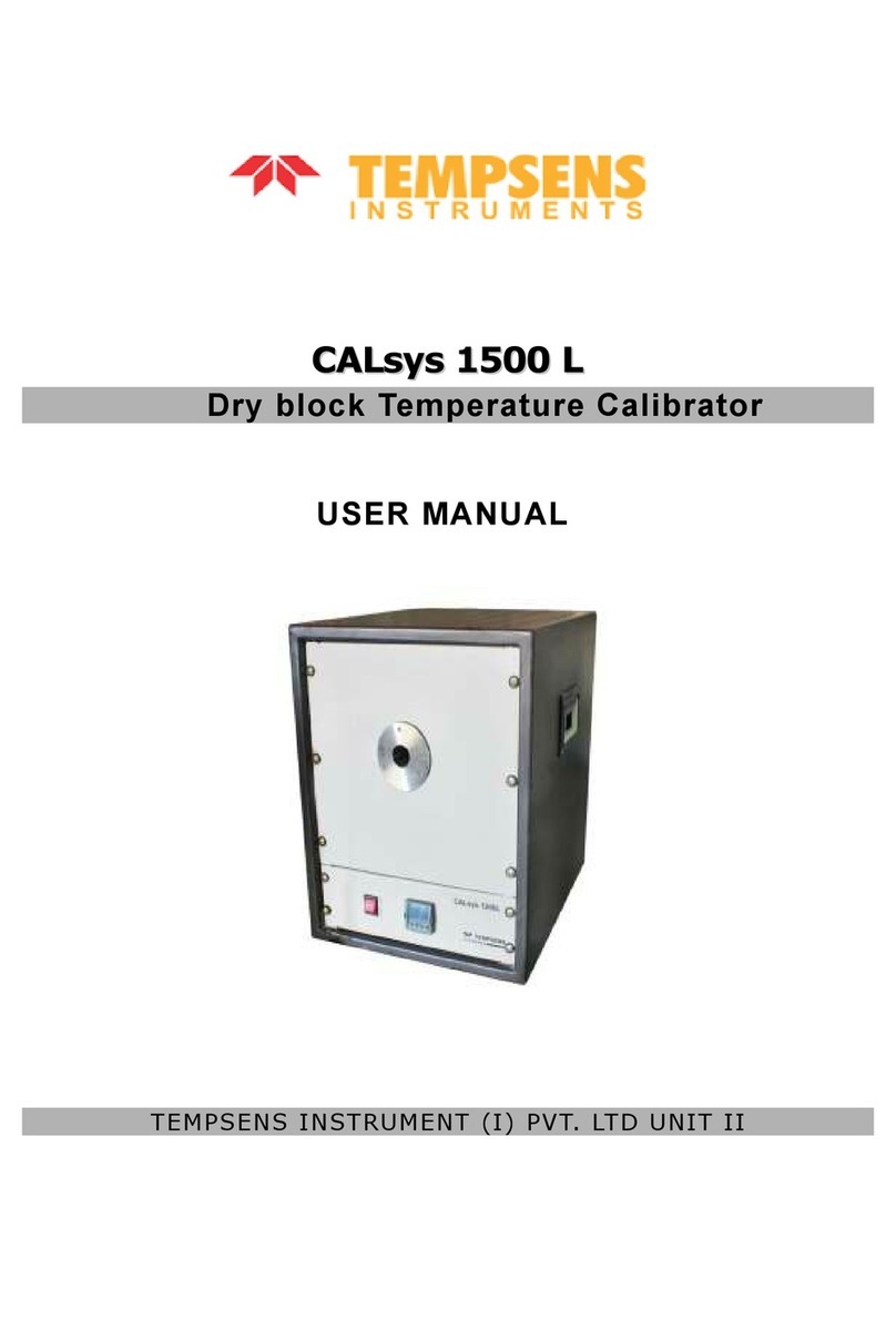
Tempsens
Tempsens CALsys 1500 L User manual
Tempsens
Tempsens CALSYS 650 User manual

Tempsens
Tempsens CALsys 1500 BB User manual

