20
4.1 Automatic satellite swap via DiSEqC™
In most cases you will aim your automatic satellite system at one specific satellite only. Of course, your system
can also receive many other satellites, allowing you to watch e.g. Dutch, Swiss, French, Spanish or other chan-
nels. You can select a satellite manually at any time via the control menu.
However, your system can also readjust to a different satellite automatically when you change to the corre-
sponding channel. This may be necessary in countries where the channels are broadcast via different satellites.
Using the automatic satellite swap requires some settings to be made at your TV set or receiver, and possibly also
at your satellite system. If these settings are not defined at all or incorrectly, the automatic satellite swap will
not work or a wrong and hence useless satellite will be received. The automatic satellite swap can be done using
the DiSEqC™ feature (disabled at the factory).
The "Automatic satellite swap" of your Oyster / Cytrac / Caro VISION satellite system has been disabled at the
factory to avoid problems and malfunctions! You can enable this feature at any time via the menu system. Note
that it is then mandatory to make the corresponding settings at your TV set or receiver!
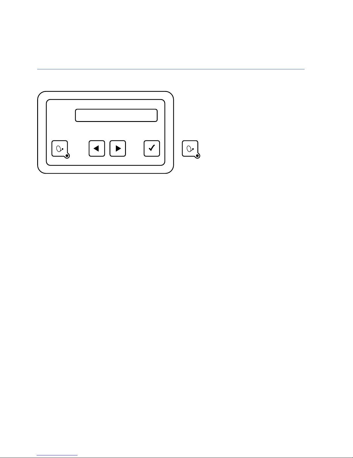
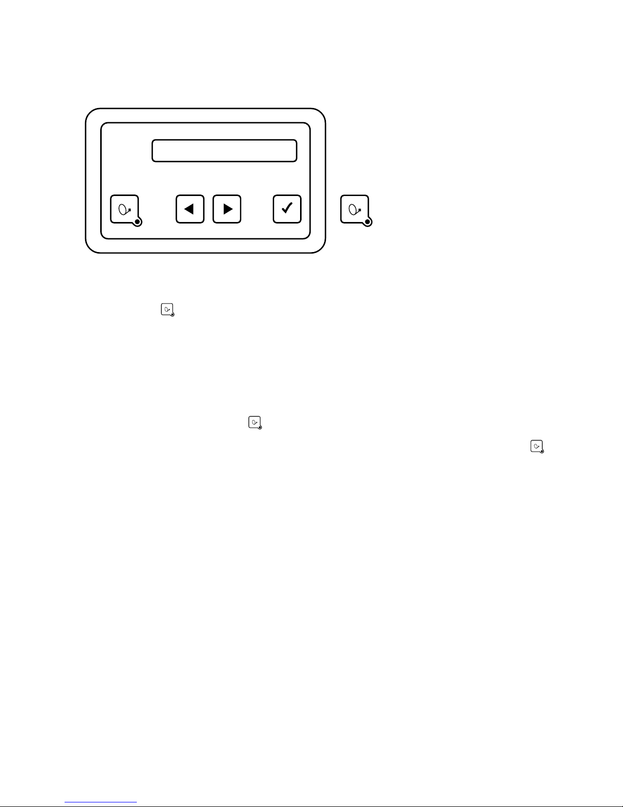
4.2 Settings at the Vision control unit
To be able to use the automatic satellite swap by means of the DiSEqC™ capability of your TV set or receiver,
you first need to enable the DiSEqC™ function in the menu of your antenna system. See page 9 "Operating the
system".
4.3 Enabling DiSEqC™ at the TV set
The settings required at the TV set or receiver are usually provided in a menu item called "DiSEqC™" or similar.
For details please refer to the user manual of your TV set or receiver or contact the dealer.
The DiSEqC™ settings should provide the options 1.0, 1.1 and 1.2. We recommend selecting DiSEqC™ 1.2. You
then need to assign a unique ID to each satellite as is already done at the Vision III control box. These IDs must
be identical in the TV settings and in the Vision III control box (see table on the following page).
If your TV set does not permit these settings, please contact your dealer.
4. AUTOMATIC SATELLITE SWAP