Tendercare Snappi Seat Standalone Instruction manual

Snappi Seat Standalone Workshop Manual
Document No: 053-08 v2 Page 1 of 49 March 2019
Snappi Seat Standalone Workshop Manual.doc
Snappi ® Seat
WORKSHOP MANUAL
This manual covers:
Size 1 and 2 Snappi Seats (standalone)
IMPORTANT
Please read these instructions carefully before using the
Snappi Seat
Please read these instructions carefully before attempting any repairs to the
seat. Repairs should only be carried out by a repairer as approved by either
Tendercare Ltd or the NHS.
My Snappi Seat Serial Numbers:
TEN/SC……….
TEN/SS…….....
Snappi Seat Standalone Workshop Manual
Document No: 053-08 v2 Page 2 of 49 March 2019
Snappi Seat Standalone Workshop Manual.doc
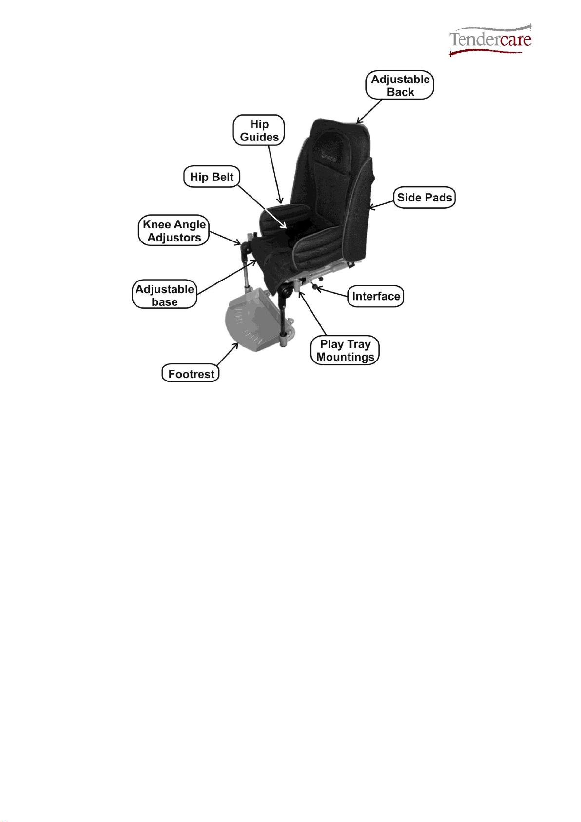
Fig 0.1 Seat unit (Size 1 shown)

Snappi Seat Standalone Workshop Manual
Document No: 053-08 v2 Page 3 of 49 March 2019
Snappi Seat Standalone Workshop Manual.doc
CONTENTS
Item
Description
Page
1
Your Snappi Seat Workshop Manual
4 - 5
2
Transit Packaging
5 - 6
3
Tools & Torque Settings
6
4
Preparing for use and operation
7
4.1 Fitting Seat to the Chassis
7
4.2 Seat Back Recline
7
4.3 Seat standard adjustments
7
5
Final Checks
8
6
Maintenance
8
6.1 Routine maintenance
8
6.2 Six monthly maintenance
8
6.3 Three yearly maintenance
8
7
Repairs
9
7.1 Seat gas spring
10 –11
7.1.1 Lock Back Recline
11 - 13
7.2 Seat Interface
13 - 14
7.3 Knee Angle Adjustor
14 - 15
7.4 Footrest Parts
16
7.4.1 Footrest Stems
16 - 17
7.4.2 Footrest Tray
17 - 18
7.4.3 Footrest Slide Assembly
18
7.5 Sun Canopy Assembly
19 - 23
7.6 Removing and Fitting Snappi Playtray receiver Brackets
24
8
Fit the minimiser kit to the Snappi Seat
25 –40
9
Convert a Snappi Minimiser to a Standard Seat
41 –48
10
Cleaning
49
11
Parts List
49

Snappi Seat Standalone Workshop Manual
Document No: 053-08 v2 Page 4 of 49 March 2019
Snappi Seat Standalone Workshop Manual.doc
1: Your Snappi Seat Standalone Workshop Manual
The purpose of this manual is to help you get the best from your seat. It does this by telling
you how to complete those maintenance and repair tasks that can be carried out by a
competent person. The manual also tells you when you should contact the manufacturer
who is:
Tendercare Ltd.
PO BOX 3091, Littlehampton, BN16 2WF
Tel: (01903) 726161 Fax: (01903) 734083
Email: [email protected]
Web: www.tendercareltd.com
IMPORTANT:
This manual must be read and used in conjunction with the user manual.
The seat unit offers best in class growth, thanks to its versatile design and large ranges of
adjustments to all supports. It has an easy to remove, breathable cover, and comes
supplied with a hip belt as standard.
Seat adjustments (please see table below for details of adjustment ranges): Seat depth
adjustment, depth and length adjustable Hip Guides, Back Height adjustment, Independent
back recline (using an easy to operate gas strut mechanism) and depth & angle adjustable
Footrest. The seat also includes an interface allowing it to be quickly fitted and removed
from the wheelbase, and like the entire Snappi range, includes all the latest safety
mechanisms (including an innovative 2 stage release to prevent little fingers causing
accidents).
The following accessories for use with the Snappi Seat are available from Tendercare Ltd.
Height and width adjustable wrap around Lateral Supports, Butterfly chest harness, Foot
and Toe Straps, Pommel, Play Tray, Standard Headrest, Extra recess Headrest, and
Occipital roll Headrest.
These instructions apply to all sizes.

Snappi Seat Standalone Workshop Manual
Document No: 053-08 v2 Page 5 of 49 March 2019
Snappi Seat Standalone Workshop Manual.doc
Snappi Seat Adjustments
Support
Snappi Seat Size 1
Snappi Seat Size 2
Seat Depth
195-295mm
290-390mm
Seat Width
190-290mm
250-350mm
Backrest Height
450-620mm
540-700mm
Footrest Depth
150-280mm
215-360mm
Back Recline Angle
90°- 135°
90°- 135°
Knee Angle*
-15°- 90°
-15°- 90°
Seat Weight
10.5Kg
13Kg
Maximum Carry Weight**
40 - 55Kg
40 - 55Kg
IMPORTANT:
* Knee angle adjustable in 15° increments
** Maximum carry weight depends on which chassis the Snappi seat is fitted to. Standard
carry weights on Tendercare bases; 40kg on Snappi and Swirl Chassis, 55kg on the
Cloud chassis. The maximum carrying weight is defined as the user weight, plus any
accessories/equipment which may be fitted or carried on the chassis. The weight of the
Snappi seat has been taken into account with these weights and you do not need to
make any deduction for the Snappi Seat. Warning: Never exceed the maximum stated
carry weight for the chassis the seat is fitted to.
All sizes and weights are given as a guide. Tendercare ltd reserves the right to amend
specifications at any time as part of their product development programme.
2: Transit Packaging
The standalone seat is supplied in a cardboard carton. This measures 410mm x 400mm x
1000mm and weighs 11.5kg (size 1) / 500mm x 450mm x 1200mm and weighs 14.5kg (size
2).
WARNING:
The transit carton is quite bulky so moving and unpacking must be done with care.
Observe all lifting and handling regulations.
Stand the carton upright making sure it is supported and cannot fall over. Open the carton
and remove any packages or packing, which could obstruct the removal of the seat and
wheelbase. Remove the seat first, then the wheelbase. Do not attempt to lift both parts out
together.
The carton should contain the following items:
Item
Component
QTY.
Yes
No
1
Size 1 or 2 Seat Unit
1
2
User Manual
1
3
5mm Alan key
1

Snappi Seat Standalone Workshop Manual
Document No: 053-08 v2 Page 6 of 49 March 2019
Snappi Seat Standalone Workshop Manual.doc
The following items should be fitted to the seat as standard:
Item
Component
QTY.
Yes
No
5
Hip guide covers
2
6
Seat Base Cover
1
7
Seat Back Cover
1
8
Side Pads
2
Please note, accessories such as lateral supports or harnessing that were ordered at the
same time as the seat will be included in the main package.
Larger accessories will be packaged in separate cartons (e.g. the rain cover).
IMPORTANT:
❖If any items are damaged or missing, then please contact Tendercare, preferably by email at
delivery.
After unpacking and checking you have all components and they are in good condition
dispose of the packaging at your local recycling centre. Alternatively retain and reuse.
3: Tools and Torque Settings
The following tools are required to dismantle, reassemble and repair the seat:
Spanners and sockets: 8mm, 10mm, 13mm
Hexagon Keys: 3mm, 4mm, 5mm and 6mm
Torque Wrench: Range 0 to 25 Nm
Screwdrivers: 2 small flat blade screwdrivers
Torque Settings if not specified:
Spanner Size (mm)
Torque (Nm)
8
10
10
15
13
25

Snappi Seat Standalone Workshop Manual
Document No: 053-08 v2 Page 7 of 49 March 2019
Snappi Seat Standalone Workshop Manual.doc
4: Preparing for use and operation
The following pre-delivery procedures should be carried out to check that the seat unit has
not suffered damage during transit and that all features operate satisfactorily. Refer to the
user manual for detailed instructions on performing each action.
4.1 Fitting the seat to the chassis
Fit the seat unit into the chassis following the instructions in section 4.3 of the seat user
manual (note the mounting system is the same for all chassis that the Snappi Seat fits to).
Checks:
•Check that the spring clips move freely and snap back to their closed position when
the lever is released
•Make sure the seat interface latches down and locks securely to the frame
•Check that the secondary latch mechanism functions correctly
•Check that the seat interface releases correctly and that there is not excessive
friction on the lever when releasing it from the frame
4.2 Seat back recline:
Test the seat back recline mechanism is working correctly by following the instructions in
section 5.1.3 of the seat user manual.
Checks:
•Make sure the gas spring moves freely through its entire range of motion when
released
•Ensure that the gas spring locks when the lever is released.
•Check that the fixing bolts for the gas spring are secure and that there is not
excessive play between the gas spring and the mounting points on the seat when
locked.
4.3 Seat standard adjustments:
All adjustments to the seat are made using hand wheels, or the 5mm hexagon key provided.
Test the adjustment ranges of the seat base, hip width, footrest depth, footrest angle and
back height as detailed in sections 5.1.1 –5.1.3 of the seat user manual.
Checks:
•Ensure all elements are free to move over their entire adjustment range (note that the
cover and harnessing may need adjusting to allow this- instructions on how to adjust
these are given in section 5 of the user manual)
•Check that all elements lock correctly
•Check that the framework is square and has not been damaged during transit.

Snappi Seat Standalone Workshop Manual
Document No: 053-08 v2 Page 8 of 49 March 2019
Snappi Seat Standalone Workshop Manual.doc
5: Final checks
1. Check that the pelvic strap or harness is secure and adjusted correctly.
2. Check that the cover is correctly fitted.
3. Check that the seat unit is located and locked correctly in the chassis.
4. Ensure the safety catch is locked.
6: Maintenance
Should a problem be found when carrying out the regular checks, it should be immediately
reported to the issuing authority or Tendercare Ltd.
6.1 Routine maintenance
The user’s family can easily carry out the following tasks. No tools are required.
1. Always wipe the seat frame dry. Never put it away damp.
2. Check operation of the reclining mechanism (weekly).
3. Clean the seat frame when necessary (we suggest at least once a week).
If you find any faults refer to your issuing authority or Tendercare Ltd.
6.2 Six-monthly maintenance
Only someone who is a competent tradesman or repairer should carry out this work. If a
major fault is found stop using the seat until it has been corrected.
1. Examine nuts, bolts, pivots and frame plugs for tightness and general condition.
2. Check the Interface fits securely into the frame, and that it is not worn or damaged.
3. Check the interface clips to ensure they can rotate freely and that the springs return
the clips to the closed position when released.
6.3 Three-yearly maintenance
1. The seat gas strut release head is cast aluminium and so we recommend this is
routinely replaced every three years.
For all other repairs refer to your issuing authority or Tendercare Ltd.

Snappi Seat Standalone Workshop Manual
Document No: 053-08 v2 Page 9 of 49 March 2019
Snappi Seat Standalone Workshop Manual.doc
7: Repairs
Only an authorised repairer should carry out the following repairs.
1. Repairs: For all repairs contact your issuing authority
2. Major repairs: For all major repairs e.g. bent or damaged frame, the seat should be
returned to the factory. Contact Tendercare ltd, customer services on 01903 726161,
3. Factory replacement components should be used in all repairs. These are available
from Tendercare. Please refer to the parts lists at the end of this manual (section 11)
for details of replacement parts.
Important points when performing a repair:
1. Do not reuse Nylock nuts, always replace with a new nut
2. Always use Loctite thread locking compound grade 241 or 243 on all threads when
reassembling any part of the system.
3. Always use the recommended component parts available from Tendercare Ltd.
4. Do not attempt to correct bent framework or perform any modifications to welded
parts. If any main framework sections are bent or damaged please return the product
to the factory.

Snappi Seat Standalone Workshop Manual
Document No: 053-08 v2 Page 10 of 49 March 2019
Snappi Seat Standalone Workshop Manual.doc
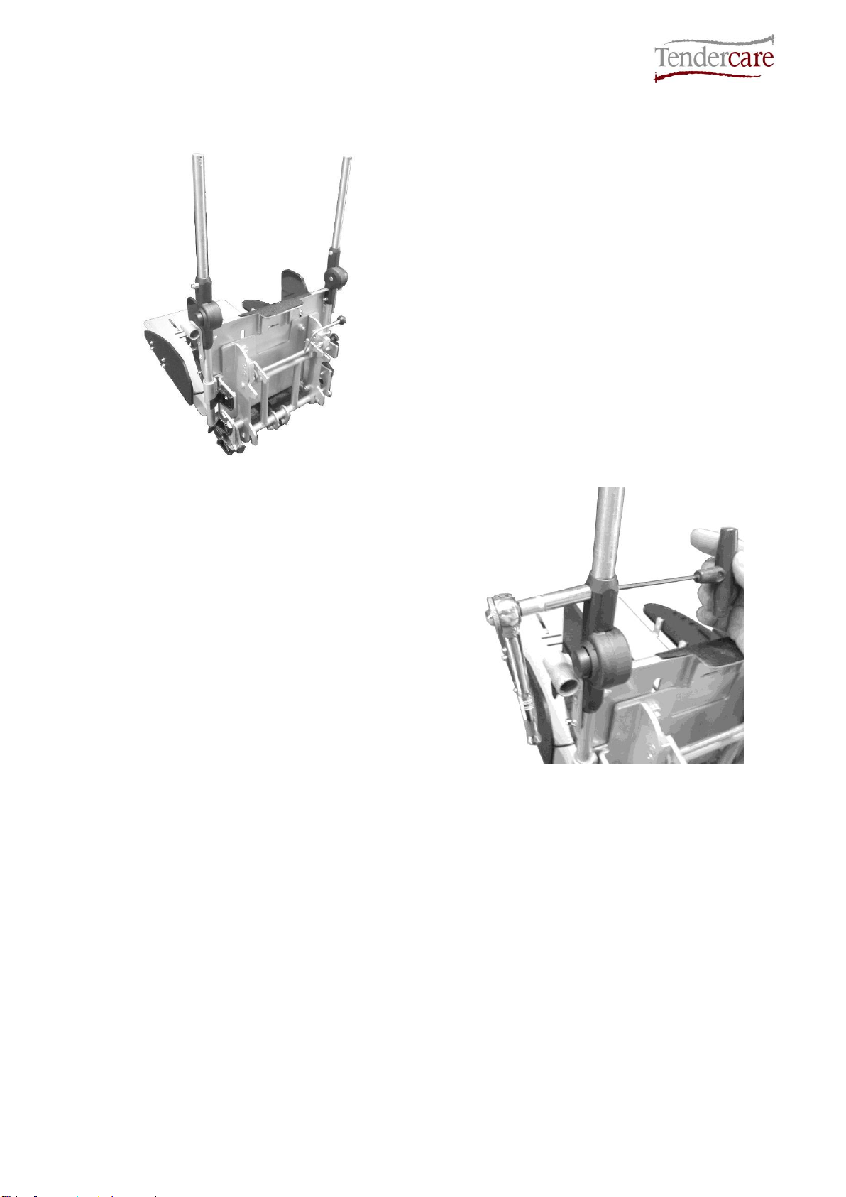
7.1: Seat gas spring/strut
Replace the gas spring if it is damaged or worn. Please note, as the gas strut release head
is cast aluminium, we recommend this is replaced every three years.
To remove the gas strut (shown in Fig 7.1.1):
Fig 7.1.1
•Lift the seat onto a suitable
workbench and sit it on its interface
with the seat back angle set at 90
degrees.
•Using 2 x 13mm spanners undo the
gas strut fixing bolts. Take note of the
position of the washers and spacers.
•Remove the release lever; undo the
release head by placing a bar (e.g.
shank of a screwdriver) through the
mounting hole in the head and loosen
with a 13mm spanner as shown in Fig
7.1.2.
•Next, unscrew the gas spring from the
head and remove the release lever.
Fig 7.1.2
•To reassemble the new gas spring,
place the release lever into the head,
and screw in the gas spring so that
the pin on the end of the gas spring
locates into the notch in the lever.
Note: for Snappi seats fitted with the
dynamic gas strut, you will need to
place the dynamic strut restrictor
between the body of the gas strut and
the m8 lock nut (see Fig 7.1.3).
Fig 7.1.3
Dynamic strut
restrictor
Gas strut body

Snappi Seat Standalone Workshop Manual
Document No: 053-08 v2 Page 11 of 49 March 2019
Snappi Seat Standalone Workshop Manual.doc
Fig 7.1.4
•Tighten the m8 lock nut until there is
no movement between the pin and
release lever, then unscrew the gas
spring by ¼ of a turn. This ensures
that there is the correct amount of
play between the pin and release
lever. Do not over tighten
•Finally secure the release head by placing a bar though the mounting hole and
tighten with the 13mm spanner.
IMPORTANT:
❖Ensure that there is a small amount of play between the release lever and pin on the end of the
gas spring. If this is too tight, the gas spring may not lock correctly, or could have the
tendency to ‘creep’ when in a locked position.
7.1.1: Lock the Back Recline
The following instructions detail how to remove the back recline adjustment lever in order to
lock the back recline in a single position.
Fig 7.1.1.1
•First, position the back rest to the
desired fixed position* (please refer to
the section 5.3.1 of the user manual
for how to adjust the angle of the
backrest).
•Next, use a 13mm spanner to loosen
the black nut on the gas strut (3 turns
should be sufficient) as shown (see
Fig 7.1.1.1, left).
M8 lock nut

Snappi Seat Standalone Workshop Manual
Document No: 053-08 v2 Page 12 of 49 March 2019
Snappi Seat Standalone Workshop Manual.doc
•Using a pair of 13mm spanners,
remove the M8 bolt that secures the
top of the gas spring the back rest of
the seat as shown (see Fig 7.1.1.2,
right). Take note of the positions of
the spacers, washers and nuts.
Fig 7.1.1.2
Fig 7.1.1.3
•Hinge the gas spring away from the
back of the chair (it will pivot on the
lower bolt) and unscrew the head a
few turns and then remove the lever.
•Screw the head back onto the gas
spring and lock in place using the
black nut and a 13mm spanner.
•Fix to the backrest using the M8 bolt,
replacing the washers and spacers in
their original position.
Fig 7.1.1.4

Snappi Seat Standalone Workshop Manual
Document No: 053-08 v2 Page 13 of 49 March 2019
Snappi Seat Standalone Workshop Manual.doc
Important:
*The Snappi Seat is only crash tested with the backrest set to a 90-degree angle. If the backrest angle
is fixed at any angle other than 90 degrees, the seat can no longer be used for transport in an adapted
vehicle.
7.2: Seat Interface
Replace the interface clips if they are damaged or bent; replace the springs if they are
stretched or overly soft in operation.
IMPORTANT
The seat interface uses 2 strong torsion springs that are under load. Care must be taken when working
on the interface clip mechanism. The following instructions are the recommended method for
dismantling the assembly to safely release the tension on the springs. If you are not confident to work
on this assembly, please return your frame to the Tendercare factory.
To dismantle the interface:
•Loosen the front screws from the
mounting using a 4mm hexagon key
as shown (right).
•Remove the rear as the tension on
the 2 torsion springs must be
released before removing the clip
mechanism from the interface frame.
Fig 7.2.1
7.2.2
To release the tension on the springs:
•Rotate the clips forward and lift the
frame so that it pivots on the 2
loosened front screws. Keep lifting
until the 2 spring arms are released
from the interface frame cross bar, as
shown (left)
•Once the springs have been released, remove the 2 front screws using a 4mm
hexagon key. The interface clip assembly can then be easily taken apart by sliding
off the 2 mounting blocks, springs and washers.

Snappi Seat Standalone Workshop Manual
Document No: 053-08 v2 Page 14 of 49 March 2019
Snappi Seat Standalone Workshop Manual.doc
Fig 7.2.3
Take note of the position of the 2 chamfers of the mounting blocks as these MUST be put
back in the correct orientation or the interface mechanism will not function properly.
Also take careful note of the orientation of the springs- the springs are handed and must be
re-fitted correctly or there will not be enough tension on the mechanism to close the clips.
To reassemble the interface, follow the reverse of these instructions and test as detailed in
section 4.4 of this manual.
7.3: Knee Angle Adjustor
Replace the seat knee angle adjustor if damaged or worn.
The replacement knee angle adjustor comes
supplied with: 1 x M5 x 30mm socket button
bolt, 1 x M5 x 35mm socket button bolt, 2 x
M5 Nylock Dome nuts, 4 x M5 Form A
Washers
Fig 7.3.1
Fig 7.3.2
Set the footrest to a horizontal position (i.e.
in line with the seat base) and place the
whole seat onto a flat surface.
Undo the nut and bolt securing the footrest
rod, taking note of the position of the bolt
head and washers, using a 3mm hexagon
key and an 8mm spanner.

Snappi Seat Standalone Workshop Manual
Document No: 053-08 v2 Page 15 of 49 March 2019
Snappi Seat Standalone Workshop Manual.doc
Next separate the footrest rod from the
adjustor as shown (right).
Fig 7.3.3
Fig 7.3.4
Undo the rear bolt securing the knee angle
adjustor (this bolt goes through the play tray
adaptor), again taking note of the position of
the washers and nuts etc. Remove the bolt
then slide the knee angle adjustor off the
frame. Note it may be helpful to loosen the
rear bolt securing the play tray adaptor if it is
difficult to slide the angle adjustor off the
frame.
Finally, slide the new adjustor onto the frame, and secure using the new bolts and nuts as
supplied (never re use nylock nuts). Please ensure that the rear fixing bolt is tightened again
if loosened in the previous step, and that the frame fixing is placed through the play tray
adaptor as before.

Snappi Seat Standalone Workshop Manual
Document No: 053-08 v2 Page 16 of 49 March 2019
Snappi Seat Standalone Workshop Manual.doc
7.4: Footrest Parts:
If a complete footrest assembly is ordered, it comes supplied with footrest slide with the tray
pre-assembled, footrest stems and the angle adjustors. For information on fitting these
please refer to the instructions given in section 7.3 (for the angle adjustors), and 7.4.1 (for
the stems) and 7.4.3 (for the slide ad tray assembly) below.
7.4.1: Footrest Stems:
To replace the footrest stems:
Fig 7.4.1.1
Remove the seat unit from the chassis and
place it on its back on a flat surface (see Fig
7.4.1.1).
Unscrew the self-tapping screws from the
end of the old footrest stems as shown (see
Fig 7.4.1.2).
Fig 7.4.1.2
Snappi Seat Standalone Workshop Manual
Document No: 053-08 v2 Page 17 of 49 March 2019
Snappi Seat Standalone Workshop Manual.doc
Fig 7.4.1.3
Make sure the footrest locking screws are
loose, and then slide the footrest assembly
off the stems (see Fig 7.4.1.3).
Using a 3mm hexagon key and an 8mm
socket or spanner, remove the M5 bolt
securing the stem to the knee angle adjustor
(as shown in Fig 7.4.1.4). Take note of the
position of the washers. Then remove the
stems.
Fig 7.4.1.4
To fit the new stems: Follow the reverse of this procedure and fit with a new Nylock dome
nut (never re-use Nylock nuts).
7.4.2: Footrest Tray:
Remove the footrest slide assembly from the pushchair, to do this:
•Remove the 2 x self-tapping screws from the end of the footrest stems.
•Loosen the footrest slide locks
•Slide the footrest assembly off the end of the stems.
For more details on this procedure please refer to section 7.4.1 above.

Snappi Seat Standalone Workshop Manual
Document No: 053-08 v2 Page 18 of 49 March 2019
Snappi Seat Standalone Workshop Manual.doc
Fig 7.4.2.1
Place the footrest slide assembly onto a flat
surface.
Using a 5mm drill bit drill off the 6 rivets that
secure the plastic tray to the metal base
plate.
Position the new foot tray onto the base
plate, so that the cut-out slots in the tray line
up with the holes in the plate. Using a 5mm
drill and the base plate as a template, drill off
the 6 mounting holes in the new foot tray.
Fig 7.4.2.2
Fig 7.4.2.3
Secure the new tray onto the base plate
using 6 x black 4.8 mm rivets (supplied).
Finally, re-attach the foot tray assembly onto the footrest stems, and secure with the 2 x
self-tapping screws.
7.4.3: Footrest Slide Assembly:
The footrest slide assembly will come pre-assembled complete with the plastic tray. To fit
the new assembly, simply remove the old slide assembly following the instructions given in
section 7.4.1 above. Slide the new assembly in place and secure back in place.

Snappi Seat Standalone Workshop Manual
Document No: 053-08 v2 Page 19 of 49 March 2019
Snappi Seat Standalone Workshop Manual.doc
7.5: Sun Canopy Assembly:
The following instructions detail how to fully assemble the sun canopy including the cover. A
separate parts list “Snappi Sun Canopy Parts List” is available on our website should any
parts need to be replaced.
Fig 7.5.1
Left: The sun canopy adjustor parts:
1: Large Teeth Adjustor
2: Small Teeth Adjustor
3: Sun Canopy Spring
4: M5 Knurled Thumbscrew
5: M5 x 25 mm Coach Bolt
Right: the assembled left-hand frame fixing
bracket (see Fig 7.5.2).
Fig 7.5.2
Fig 7.5.3
To assemble the sun canopy, lay out the 2
frame bars and 2 fixing brackets as shown
(see Fig 7.5.3, left).
Front Bar
Rear Bar
1
2
3
4
5

Snappi Seat Standalone Workshop Manual
Document No: 053-08 v2 Page 20 of 49 March 2019
Snappi Seat Standalone Workshop Manual.doc
Take the front bar and feed into the front
fitting tube in the cover as shown (see fig
7.5.4, right).
Fig 7.5.4
Fig 7.5.5
Left: The front frame bar fitted to the cover
(see Fig 7.5.5).
Next, take the rear bar and feed into the rear
fitting tube as shown (see fig 7.5.6, right).
Fig 7.5.6
Table of contents


