Tenma 72-820 User manual

1
Model: 72-820 and 72-823
Infrared Thermometer

2
Please read these instructions carefully before use and retain for future reference.
•Please operate according to this manual, otherwise the protection provided by the
device will be impaired or fail.
•Do not point laser directly in your eyes or indirectly off reective surfaces.
•Check the condition before using. If you nd any cracking, breakage, damage or
abnormality, or you consider the device broken, stop using the device immediately
•Do not use the Thermometer if it operates abnormally. Protection may be impaired.
When in doubt, have the Thermometer serviced.
• Do not operate the Thermometer around explosive gas, vapor, or dust.
•To avoid a burn hazard, remember that highly reective objects will often result in
lower than actual temterature measurements.
•To avoid damaging the thermometer or the equipment under test protect them from
the following:
EMF (electro-magnetic elds) from arc welders, induction heaters, etc.
Static electricity.
Thermal shock (caused by large or abrupt ambient temperature changes –
allow 30 minutes for the Thermometer to stabilize before use).
•Do not leave the Thermometer on or near objects of high temperature.
• Replace the batteries as soon as the low battery indicator appears on the display.
•Remove dead batteries from the Thermometer or if it is not going to be used for a
long time.
• Never mix old and new batteries together, or different types of batteries.
•Never dispose of batteries in a re, or attempt to recharge ordinary batteries.
•Before replacing the battery, turn off the Thermometer and disconnect all the test
probes.
• To prolong battery life turn off the Thermometer after use.
IMPORTANT SAFETY INFORMATION
WHAT’S INCLUDED
FEATURES
• Infrared Thermometer with laser sighting.
•9V 6F22 Alkaline Battery (included)
• Instruction manual
• Single-spot laser sighting.
•Intelligent USB power input (does not charge internal battery).
• Backlit display - Two level white/colour (when using USB power, this feature will be
on automatically).
• Current temperature plus
MIN, MAX, DIF, AVG
temperature readings.
• Easy emissivity selector.
• Trigger lock.
• Celsius and Fahrenheit
temperature measurement.
• Tripod mount.

3
Display
• The primary temperature display reports the current or last IR temperature read
until the 8-second hold time elapses.
• The secondary temperature display reports a choice of maximum, minimum,
difference between maximum and minimum temperature or average value.
• You can toggle through the maximum, minimum, difference and average IR
temperatures anytime the display is on.
• The MAX, MIN, DIF and AV temperatures are constantly calculated and updated
when the trigger is pressed.
• After the trigger is released, the MAX, MIN, DIF and AV temperatures are held for 8
seconds.
Laser on symbol
HOLDSCAN Scan or hold
oC / oF Celcuis / Fahrenheit
A Primary temperature Display
B Secondary temperature Display
C Emissivity LO, MED, HI
D Temperature values for the MAX, MIN, DIF, AVG
Low Battery symbol. Appears when the battery charge is <4.5V.
• After connecting the USB cable, the Thermometer automatically selects USB power
supply and two levels white colour backlit display will be
on.
Note: The USB connection does not charge the internal battery.
It is for external power only for when the Thermometer is in use
over extended periods.

4
Press SET to enter set up mode
stepping through Emissivity set up,
trigger lock and switching oC/oF set up.
Press MODE button to toggle between
MAX, MIN, DIF, and AVG options.
Press MODE to turn the Thermometer on
again and displays the last measurement
result.
Press *to turn on laser target function
When Thermometer enters user set up
mode use ▲to select a further option.
Press to turn on the display
backlight. When Thermometer enters
user set up mode use ▼to select a
further option.
Button operation.
OPERATION FUNCTION
•Infrared thermometers measure the surface temperature of an opaque object. The
Thermometer’s optics sense infrared energy, which is collected and focused onto
a detector. The Thermometer’s electronics then translate the information into a
displayed temperature reading which appears on the display. The laser is used for
aiming purposes only.
• The Thermometer turns on when you press the trigger. The Thermometer turns off
when no activity is detected for 8 seconds.
• To measure temperature, aim the Thermometer at the target, pull and hold the
trigger. Release the trigger to hold a temperature reading.
•To nd a hot or cold spot, aim the Thermometer outside the target area. Then,
slowly scan across the area with an up and down motion until you locate the hot or
cold spot.
Distance and target spot size
•As the distance (D) from the target being measured increases, the spot size (S) of
the area measured by the unit becomes larger. The spot size indicates 90%
encircled energy. The maximum D:S is obtained when the Thermometer is 600mm
(23.62in) from the target resulting in a spot size of 20mm (0.78in).
• Make sure that the target is larger than the spot size.

5
Emissivity
• Emissivity describes the energy-emitting characteristics of materials. Most organic
materials and painted or oxidized surfaces have an emissivity of about 0.95.
• If possible, to compensate for inaccurate readings that may result from measuring
shiny metal surfaces, cover the surface to be measured with masking tape or at
black paint (<150 oC / 302 oF) and use the high emissivity setting. Allow time for the
tape or paint to reach the same temperatures as the surface beneath it. Measure
the temperature of the tape or painted surface.
• If you cannot use paint or use tape, then you could improve the accuracy of your
measurements with the emissivity selector. Even with emissivity selector, it can be
difcult to get a completely accurate infrared measurement of a target with a shiny
or metallic surface.
•The Thermometer allows you to adjust the unit’s emissivity for the type of surface.
To adjust values for emissivity (see table below):
1. Press SET to select emissivity set up, icon E on the display will flash. The
Thermometer steps through emissivity set up, trigger lock and switching oC / oF.
2. Press ▲ to increase the value by 0.01 or press and hold ▲to access quick setting.
The maximum value is 1.00.
3. Press ▼to decrease the value by 0.01or press and hold ▼to access quick
setting. The minimum value is 0.10.
Measure Surface (metals) Switch Setting
Aluminium oxydised 0.2-0.4
Alloy A3003 oxydised 0.3
Alloy A3003 roughened 0.1-0.3
Burnished Brass 0.3
Oxidised Brass 0.5
Copper oxydised 0.4-0.8
Electrical terminal blocks 0.6
Haynes alloy 0.3-0.8
Inconel oxydised 0.7-0.95
Inconel sandblasted 0.3-0.6
Inconel electropolished 0.15
Cast Iron oxydised 0.6-0.95
Cast Iron clean 0.2
Cast Iron molten 0.2-0.3
Wrought Iron dull 0.9
Lead rough cast 0.4
Lead oxydised 0.2-0.6
Molydbenum oxydised 0.2-0.6
Nickel oxydised 0.2-0.5
Platinum black 0.9
Steel cold rolled 0.7-0.9
Steel ground sheet 0.4-0.6
Steel polished sheet 0.1
Iron oxydised 0.5-0.9
Iron rusted 0.5-0.7
Zinc oxydised 0.1

6
Measure Surface (non-metals) Switch Setting
Asbestos 0.95
Asphalt 0.95
Basalt 0.7
Carbon clean 0.8-0.9
Graphite 0.7-0.8
Carborundum 0.9
Ceramic 0.95
Clay 0.95
Concrete 0.95
Cloth 0.95
Plate glass 0.85
Gravel 0.95
Gypsum 0.8-0.95
Ice 0.98
Limestone 0.98
Paper (any colour) 0.95
Opaque plastic 0.95
Soil 0.9-0.98
Water 0.93
Wood (natural) 0.9-0.95
Trigger Lock
• Press SET and when lock icon displays select ▼to set on or off.
• When the trigger is locked, the Thermometer will provide continuous measurement.
There is no need to pull the trigger.
• When the trigger is unlocked, the user must pull the trigger for measurement.
When the trigger is released, the Thermometer will hold the measurement result
automatically. HOLD appears in the display until the trigger is pulled again.
Temperature units
• Press SET to enter centigrade or fahrenheit mode then select ▼to set selection.
OPERATION EXAMPLES
Testing Contactors
• Press SET to select emissivity. Press ▲/▼to select relatively low emissivity for
bright contacts, or 0.7 mid level for darkened contacts.
• Press MODE to select MAX.
• Measure line and load side of one pole without releasing trigger.
• A temperature difference between the line and load sides of a pole indicate
increased resistance of one point and a contactor may be failing.
Testing Enclosed Relays
• Press SET and then press ▲/▼to set emissivity to relatively low for uninsulated
connectors or relatively high for plastic encased relays or for bakelite enclosed
relays or insulated connectors.
• Press MODE to select MAX. Start to scan.
• Measure the relay casing, looking for hot spots.

7
Testing Fuses and Bus Connectors
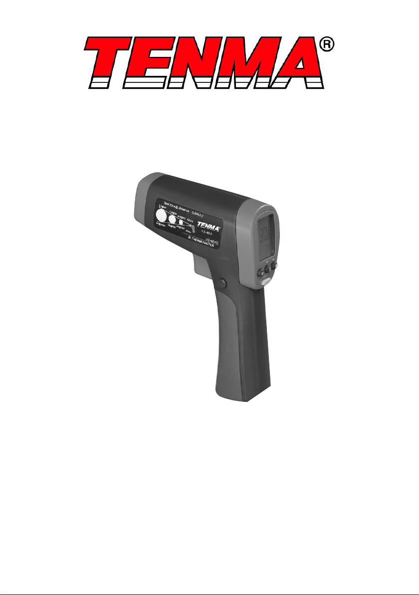
• Press SET and then press ▲/▼to set emissivity to relatively high for paper covered
fuse body or insulated connections.
• Press MODE to select MAX.
• Scan the paper covered length of fuse.
• Without releasing the trigger, scan each fuse. Unequal temperatures between fuses
may indicate voltage or amperage imbalance.
• Press SET and then press ▲/▼to set emissivity to relatively low, for metal fuses
and caps and insulated bus connections.
Testing Electrical Connections
• Press SET and then press ▲/▼to set emissivity to relatively low for uninsulated
connectors or buss connections or relatively high for insulated connections.
• Scan the conductor, moving toward direction of electrical connector.
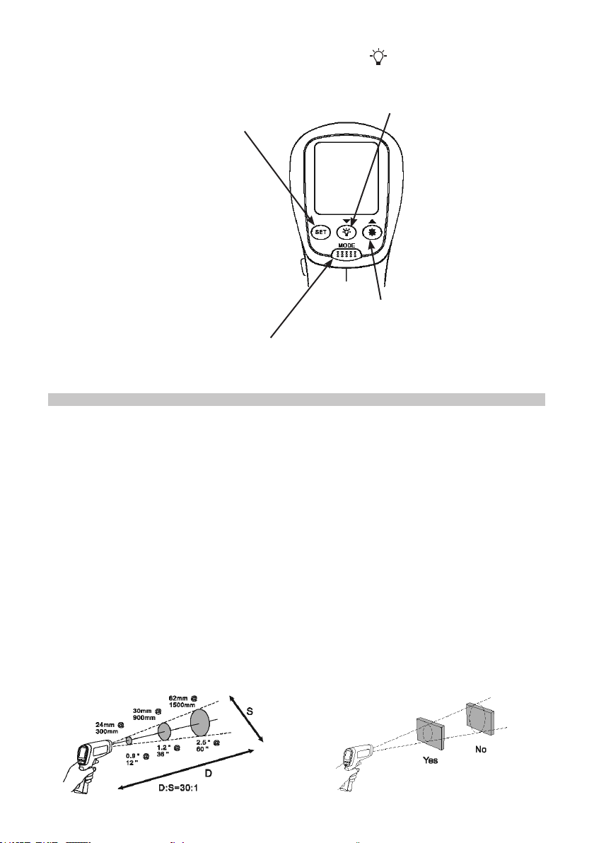
Note: conductors are typically smaller than the Thermometers spot size. If the spot size
is bigger than the connector the reading is the average within the spot.
Scanning walls for air leaks or insulation deciencies
• Turn off heating, cooling, and blower.
• Press SET to select emissivity.
• Press ▲/▼to select emissivity relatively high for painted surfaces or window
surfaces.
• Press MODE to select MIN when opposite side of wall is at lower temperature and
or select MAX when opposite side of wall is at higher temperature.
• Measure an interior partition wall surface temperature. Do not release the trigger.
• Record this temperature as your baseline (or benchmark) for a “perfectly” insulated
wall.
• Face the wall to be scanned. Stand 1.5m away to scan a 5cm spot on the wall.
Scan horizontal rows of wall from top to bottom, or horizontal rows of ceiling from
wall to wall.
Look for greatest deviations from baseline temperature to identify problems.
• This completes the insulation test scan.
Checking Hydronic radiant heat applications
• Radiant heat tubes in the oor will normally run parallel to the outside walls.
Starting at the oor wall juncture, scan parallel to the wall while moving into
the room away from the wall. Parallel to the outside wall you should nd
parallel isothermal rows indicating the location of heat tubes below the surface.
Perpendicular to the outside wall, you should nd rising and falling temperatures at
equal distances. High temperatures indicate you are scanning a heat tube beneath
the oor surface, low falling temperatures indicate a space between the heat tubes.
Measuring Grille or Diffuser Discharge Temperature
• Press SET and then press / to select relatively high emissivity.
• Aim the Thermometer at the discharge air grille, register, or diffuser.
• Measure discharge temperature.
• Release trigger to freeze the temperature reading for 8 seconds and record this
temperature. Grille, register, or diffuser temperature should be equivalent to
discharge temperature at the air handler.

8
MAINTENANCE
SPECIFICATIONS
Changing the battery
• To install or change the 9V battery, open the battery compartment. Replace only
with the same type of battery.
Cleaning the lens
Blow off loose particles using clean compressed air. Carefully wipe the surface with a
moist cotton swab. The swab may be moistened with water.
Cleaning the casing
• Wipe using a damp cloth or sponge. Do not use solvents as these may damage the
casing. Do not immerse in water.
Infrared
Measurement Range (72-820) 18oC to 550oC (0oF to 1022oF)
Measurement Range (72-823) -32oC to 650oC (-25oF to 1200oF)
Spectral Range 8 to 14 microns
Accuracy 1.8% or (1.8oC/4oF)
Repeatability 0.5% of reading or 1oC/2oF
Response Time (95%) 250ms
Distance to Spot (72-820) 12:1
Distance to Spot (72-823) 20:1
Emissivity adjustment 0.10~1.00
Display resolution ±0.1oC (0.1oF)
Laser
Sighting Single point laser
Power Class 2 Output <1mW, wavelength 630 to 670mm
Power Supply 6F22 9V Battery
Power consumption over 30hrs (alkaline) or over 10hrs (gp)
Weight 0.322kg
INFORMATION ON WASTE DISPOSAL FOR CONSUMERS OF
ELECTRICAL & ELECTRONIC EQUIPMENT
These symbols indicate that separate collection of Waste Electrical and Electronic Equipment
(WEEE) or waste batteries is required. Do not dispose of these items with general household
waste. Separate for the treatment, recovery and recycling of the materials used. Waste batteries
can be returned to any waste battery recycling point which are provided by most battery retailers.
Contact your local authority for details of the battery and WEEE recycling schemes available in
your area. Made in China. PR2 9PP
Man Rev 1.0
Other manuals for 72-820
1
This manual suits for next models
3
Table of contents
Other Tenma Thermometer manuals