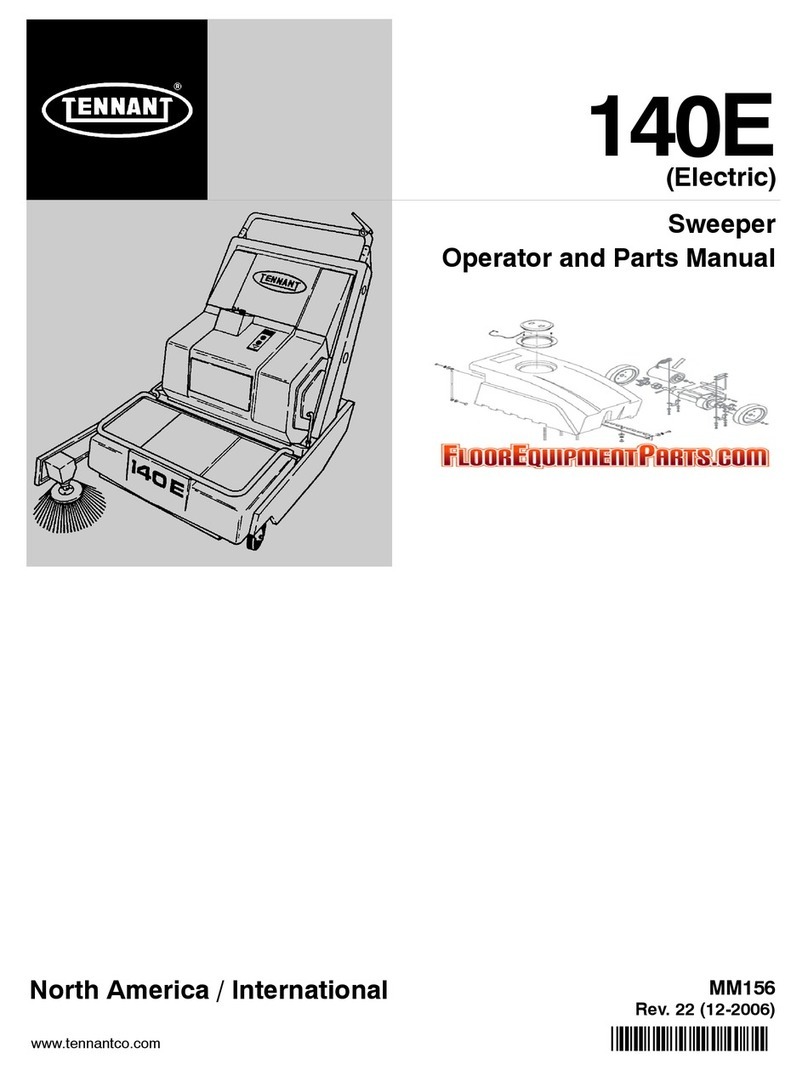
Tennant 215E User manual

215E
MM158
Operatorand PartsManual

Thismanual isfurnished with each newTENNANTModel215E
ThismanualconsistsofSpecifications; Operation;Maintenance;Appendix; the HowToUseThisManual;
Low DumpModelParts;Multi--Level DumpModelParts; Options;HydraulicComponents;and Cross
Referencesections.
MACHINEDATA
Pleasefill outat timeofinstallationforfuturereference.
MachineModelNumber---215E
MachineSerialNumber---
MachineOptions---
TENNANTRepresentative/phoneno.---
CustomerIDNumber---
DateofInstallation---
ManualNumber---MM158
Revision:11
Published:2---98
CopyrightE1986,1987,1988,1989,1990,1991,1993,1994,1998 TENNANT,Printed inU.S.A.

GENERALINFORMATION
i
215EMM158 (11--91)
SAFETY PRECAUTIONS
The following symbolsare used throughout this
manualasindicated intheirdescriptions:
WARNING:To warn ofhazardsor
unsafepractices whichcouldresultin
severepersonal injuryordeath.
FORSAFETY:To identify actionswhich
mustbefollowedforsafeoperation of
equipment.
The following information signalspotentially
dangerous conditionstothe operatoror
equipment. Read thismanualcarefully.Know
when theseconditions can exist. Locate all safety
deviceson the machine.Then, take necessary
stepstotrainmachine operating personnel.
Reportmachine damage orfaultyoperation
immediately.Do notusethe machine ifitisnotin
properoperating condition.
FORSAFETY:
1.DoNotOperateMachine:
-- Unless TrainedAnd Authorized.
-- Unless Operation Manual IsReadAnd
Understood.
-- In FlammableOrExplosive Areas
Unless Designed ForUse In Those
Areas.
-- InAreas WithPossibleFalling Objects
Unless EquippedWithOverhead
Guard.
2.BeforeStarting Machine:
-- Make SureAll SafetyDevices AreIn
Place And OperateProperly.
-- Check Brakes And Steering ForProper
Operation.
3.WhenStarting Machine:
-- Keep FootOnBrake And Directional
Pedal InNeutral.
4.WhenUsing Machine:
-- Use Brakes To Stop Machine.
-- GoSlow OnGrades And Slippery
Surfaces.
-- Use CareWhenBacking Machine.
-- Move MachineWithCareWhen
HopperIsRaised.
-- Make SureAdequateClearance Is
AvailableBeforeRaising Hopper.
-- DoNotCarryRidersOnMachine.
-- AlwaysFollowSafetyAndTraffic
Rules.
5.BeforeLeaving OrServicing Machine:
-- Stop On LevelSurface.
-- SetParking Brake.
-- TurnOff MachineAnd Remove Key.
6.WhenServicing Machine:
-- AvoidMoving Parts.DoNotWear
Loose Jackets,Shirts, OrSleeves
WhenWorking OnMachine.
-- Block MachineTires Before Jacking
MachineUp.
-- Jack MachineUpAtDesignated
LocationsOnly.Block MachineUp
WithJack Stands.
-- Use HoistOrJack OfAdequate
CapacityTo Lift Machine.
-- WearEye And EarProtection When
Using PressurizedAirOrWater.
-- DisconnectBatteryConnections
BeforeWorking OnMachine.
-- AvoidContactWithBatteryAcid.
-- Use Cardboard To LocateLeaking
HydraulicFluidUnderPressure.
-- Use TENNANTSuppliedOrEquivalent
ReplacementParts.
WARNING:Batteries EmitHydrogen
Gas.Explosion OrFireCanResult.
KeepSparks And Open FlameAway.
KeepCoversOpenWhenCharging.
WARNING:RaisedHopperMay Fall.
EngageHopperSupportBar.

GENERALINFORMATION
215EMM158 (11--91)
ii
efollowing safetylabelsaremounted on the
machine inthe locationsindicated. If these,orany
labelbecomesdamaged orillegible,install a new
label initsplace.
HOPPERWARNINGLABEL-- LOCATEDON
THEHOPPERSIDEOF THEFRONT
SUPPORTPARTITION.
BATTERYCAUTIONLABEL-- LOCATEDON
THEOPERATORSIDEOF THEFRONT
SUPPORTPARTITION.
HOPPERSUPPORTBAR WARNINGLABEL
-- LOCATEDONTHEHOPPERSUPPORT
BAR.
HOPPERSUPPORTBAR WARNINGLABEL
-- LOCATEDONTHEOPERATORSIDEOF
THEHOPPER.
FORSAFETYLABEL-- LOCATEDONTHE
SEATSHROUD.
07193

SPECIFICATIONS
1-1
215EMM158 (6--88)
SECTION1
CONTENTS
Page
MACHINE SPECIFICATIONS1-3............
POWERTYPE 1-3......................
POWERTRAIN1-3.....................
STEERING1-3.........................
HYDRAULICSYSTEM1-3...............
BRAKINGSYSTEM1-3.................
SUSPENSIONSYSTEM1-3.............
SYSTEMFLUID CAPACITIES 1-3........
GENERALMACHINEDIMENSIONS--
CAPACITIES 1-3.....................
MACHINEWEIGHTS1-3................
GENERALMACHINE PERFORMANCE1-3
MACHINEDIMENSIONS1-4................

SPECIFICATIONS
215EMM158 (6--88)
1-2

SPECIFICATIONS
1-3
215EMM158 (11--91)
MACHINE SPECIFICATIONS
POWERTYPE
Electricpropelling motor-- nominalvoltage 36
VDC 1.9hp(0.14 kW)@320 rpm,50 A
Batteries,standard(6) -- 6V,220 A/h@20 hour
rate
heavy duty(6) -- 6V,305 A/h@20 hour rate
Battery charger -- 36 VDC 20 A,120 VAC input
24 VDC,15 A,115/230 VAC
POWERTRAIN
Propelling -- hydrostatictransmission,beltdriven
Differential-- chain driven
Drive axle(2) -- chain driven
Main brush-- beltdriven
Side brush-- beltdriven
Vacuumfan -- beltdriven
Hydraulicpump-- electricmotordriven
STEERING
Type -- rearwheelcontrolled,automotivecam
and lever
Powersource-- manual
HYDRAULICSYSTEM
Function -- operateshopperlift on multi--level
dumpmodel
Controlvalve-- solenoid operated,pump
mounted
Pump-- geartype,0.065 cuin(1cc)
displacementper revolution,1250 psi
(8620 kPa)@1.0 gpm (4 L/min)
reliefsetting
Cylinder -- single action type,2in(50 mm) borex
11 in(280 mm) stroke,1in(25 mm)
diameter rod,2500 psi(17,240 kPa)
maximum rated pressure.
BRAKINGSYSTEM
Service brakes-- mechanicaldisc brakes(2) --
1 perfrontwheel,cable actuated
Parking brakes-- utilizes service brakes,cable
actuated
SUSPENSIONSYSTEM
Front-- 12 x3.00 zero pressuretires(2)
Rear -- 12 x3.00 solidtire(1)
SYSTEMFLUID CAPACITIES
Hydrostatictransmission -- 1.6 pt(0.75 L)
Hydraulic system -- reservoir2 qt(1.8 L)
Hydraulic system -- total2.5 qt(2.4 L)
GENERALMACHINEDIMENSIONS--
CAPACITIES
Length-- 63.75 in(1620 mm)
Width-- 46.75 in(1190 mm) withside brush
Height-- 53.75 in(1365 mm) less overhead
guard
Height-- 79 in(2005 mm) with overhead guard
Track -- front42 in(1065 mm)
Wheelbase-- 35.5in(900 mm)
Main brush-- width36in(915 mm)
Main brush-- outside diameter10 in(255 mm)
Side brush-- rotarydiameter17 in(430 mm)
Sweeping pathwidth(total) -- 46 in(1170 mm)
Hoppercapacity-- 6cuft (0.17 m#)
320 lb(145 kg)
Dust filter -- 42 sqft (3.9m@),pleated panel
filterelement
MACHINEWEIGHTS
Netweight, dry-- 1060 lb(480 kg)
GVWR-- 2205 lb(1000 kg)
GENERALMACHINE PERFORMANCE
Maximumforwardspeed -- 4.5mph (7km/h)
Maximum reversespeed -- 2mph (3km/h)
Turning radius-- 67 in(1700 mm)

SPECIFICATIONS
215EMM158 (11--91)
1-4
MACHINEDIMENSIONS
SIDEVIEW
TOPVIEW
63.75 in(1620 mm)
53.75 in
(1365 mm)
46.75 in
(1190 mm)
07194

OPERATION
2-1
215EMM158 (4--90)
SECTION2
CONTENTS
Page
PREPARATIONFOROPERATION2-3.......
AFTER UNCRATINGAND BEFORE
OPERATINGMACHINE:2-3..........
OPERATIONOFCONTROLS2-4...........
MACHINECOMPONENTS2-4...........
INSTRUMENTPANELSYMBOLS2-5.....
CONTROLS AND INSTRUMENTS2-6....
BRAKE PEDAL 2-7.....................
DIRECTIONALPEDAL 2-7...............
PARKINGBRAKE LEVER2-7............
CHARGERTIMER2-7..................
CHARGERGAUGE2-7.................
BATTERYDISCHARGEINDICATOR2-7. .
VOLTMETER2-7.......................
HOUR METER2-7......................
HAZARD LIGHTSWITCH 2-7............
LIGHTS SWITCH 2-8...................
FILTERSHAKERSWITCH 2-8...........
HOPPER DOORSWITCH 2-8............
HOPPERSWITCH 2-8..................
HORN BUTTON2-8.....................
KEY-OPERATEDON-OFF SWITCH 2-8...
STARTSWITCH 2-8....................
MAINBRUSHPOSITIONLEVER2-8.....
SIDE BRUSHPOSITIONLEVER2-8......
STEERINGWHEEL 2-8.................
MAINBRUSH HEIGHTADJUSTMENT
KNOB2-9...........................
CHARGERPANEL 2-9..................
CIRCUITBREAKERS AND FUSES 2-9....
HOPPERSUPPORTBAR2-10............
TOENGAGEHOPPER
SUPPORTBAR2-10...............
TODISENGAGEHOPPER
SUPPORTBAR2-10...............
Page
MACHINEOPERATION2-11.................
NORMALSWEEPING OPERATION2-11...
PRE-STARTCHECKLIST2-11.........
TOSTARTMACHINE2-11.............
TOSWEEP 2-11......................
TODUMPHOPPER2-12..............
POSTOPERATION CHECKLIST--
MOTOROPERATING2-12..........
TOSTOPMACHINE2-12..............
POSTOPERATION CHECKLIST--
MOTORSTOPPED2-12............
OPERATIONONGRADES 2-12...........
MACHINETROUBLESHOOTING2-13.....
TRANSPORTINGMACHINE2-14............
PUSHING ORTOWINGMACHINE2-14....
MACHINEJACKING2-14.................
TOJACKUPMACHINE2-14...........
MACHINETIE-DOWNS2-15..............
MACHINE STORAGE2-16..................
STORINGMACHINE2-16................

OPERATION
215EMM158 (2--98)
2-2

OPERATION
2-3
215EMM158 (11--91)
PREPARATIONFOROPERATION
AFTER UNCRATINGAND BEFORE
OPERATINGMACHINE:
1.Check the machine forshipping damage.
2.Read thismanualcarefullybefore operating
orservicing the machine.
FORSAFETY:DoNotOperateMachine,
Unless Operation Manual IsReadAnd
Understood.
3. Open the seatsupport.
4.Check the batteries. If theyare of the
wet-type,check the electrolytelevel. If they
are of the dry-type,activatethemas
described inACTIVATINGDRY-TYPE
BATTERIES inthe MAINTENANCEsection.
AB
00879
CHECKINGBATTERY ELECTROLYTELEVEL
A.Battery
B.ElectrolyteIndicatorRing
FORSAFETY:WhenServicing Machine,Avoid
ContactWithBatteryAcid.
5.Check the battery specificgravityto
determine the state ofcharge asdescribed
inBATTERIES inthe MAINTENANCE
section.Charge the batteriesifnecessary.
6.Connect thebatteries-to-machine
connector.
A
B
03065
CONNECTINGBATTERIES-TO-MACHINE
CONNECTOR
A.MachineConnector
B.Batteries Connector
7.Multi-leveldumpmodelmachines:Check
the hydraulicfluidlevel inthe hydraulicfluid
reservoir.See HYDRAULICSinthe
MAINTENANCEsection.
8.Check the transmission fluidlevel.See
HYDRAULICSinthe MAINTENANCE
section.
9.Check the main brush adjustment. See
BRUSHES inthe MAINTENANCEsection.

OPERATION
215E MM158 (11--91)
2-4
OPERATION OF CONTROLS
A
B
C
D
E
F
G
H
03085
MACHINE COMPONENTS
A. Operator Seat E. Hopper
B. Steering Wheel F. Side Brush
C. Instrument Panel G. Access Door
D. Filter Cover H. Seat Support

OPERATION
2-5
215EMM158 (11--91)
INSTRUMENTPANELSYMBOLS
Thesesymbolsare used toidentify controlsand
displays on the machine:
Side BrushDown
Side BrushUp
MainBrushDown
MainBrushUp
MainBrushExtraDownPressure
HopperDoorClose
HopperDoorOpen
HopperUp
HopperDown
FilterShaker
Start
Hazard Light
OperationalLights
KeySwitch
Horn
InterruptSwitch
BatteryChargerInterrupt
BatteryCharger
Battery

OPERATION
215EMM158 (11--91)
2-6
QC
T
B
A
O
F
E
D
H
G
IJKLMNP
R
S
U
V
(Formachines serialnumber000000 to003859)
(Formachines serialnumber003860 andabove)
03086
CONTROLSAND INSTRUMENTS
A.Brake PedalL.HopperDoorSwitch
B.DirectionalPedalM.HopperSwitch
C.Parking Brake LeverN.HornButton
D.ChargerTimerO. Key-OperatedOn-off Switch
E.ChargerGaugeP.StartSwitch
F.CircuitBreakersQ. MainBrush Lever
G. BatteryDischargeIndicator/R.SideBrush Lever
VoltmeterS.Steering Wheel
H.HourMeterT.MainBrushAdjustmentKnob
I. Hazard LightSwitchU.Parking Brake Release Lever
J.LightsSwitchV.ChargerPanel
K.FilterShakerSwitch

OPERATION
2-7
215EMM158 (11--91)
BRAKE PEDAL
The brake pedaloperatesthe mechanicaldisc
brakeson the twofrontwheels.
Tostop the machine,returnthe direction control
pedalto neutral, then applypressuretothe brake
pedal.
DIRECTIONALPEDAL
The directionalpedalcontrolsthe propelling drive.
It isused toselect the direction of traveland the
speed of the machine.
B
C
A
D
E
00116
DIRECTIONALPEDAL
A.“Reverse”Position
B.“Neutral”Position
C.“Forward”Position
D.“Toe”Portion
E.“Heel”Portion
Graduallypress the “toe”portion of the pedalfor
forwardtravelorthe “heel”portion for reverse
travel.Regulatethe machine speed by varying the
pressureonthe controlpedal.
If the machine creepswhen the pedal isinthe
“neutral”position,adjust the directionalcontrol
pedal.
NOTE:Always usethe brake pedalfornormal
stopping and controlling speed on down grades.
PARKINGBRAKELEVER
The parking brakeleveroperatesthe frontwheel
disc brakes.Toset the parking brake,pull the
handle up.Toreleasethe parking brake,pull the
releaselever.Always parkonalevelsurface,stop
the engine,and set the parking brake before
leaving the machine unattended and before
working on the machine.
FORSAFETY:BeforeLeavingOrServicing
Machine;StopOnLevelSurface,SetParking
Brake,TurnOff TheMachineAndRemove
Key.
CHARGERTIMER
The chargertimercontrolsthe battery chargeron
machinesbelowserialnumber003860.Tostart
the battery charger, turnthe timerknob tothe
numberofhours you wishtocharge the batteries.
The timerwill automatically stop the charger.
CHARGERGAUGE
The chargergauge indicatesthe levelofcharge
being passed tothe batterieson machinesbelow
serialnumber003860.The gauge needleshould
be inthe green area when charging and inthe
black area when done.
BATTERYDISCHARGEINDICATOR
The batterydischarge indicatorisan option on
machinesbelowserialnumber003860. It
indicatesthe presentstate ofcharge of the
batteries.The display shouldbeonthe Fmarkof
the gauge when the batteriesarefully charged.
Asthe batteriesdischarge, the displaywill move
down nearthe Emark.The batteries should be
recharged when the displaygetstothe 1/4mark.
VOLTMETER
The voltmeterindicatesthe presentstate of
battery charge on machines serialnumber003860
and above.The needleshouldbeinthe white
zone when the batteriesarefully charged.Asthe
batteriesdischarge, the needlewill moveintothe
green zone.Recharge the batterieswhen the
needleconsistently stays inthe red zone.
NOTE:Do notcharge the batteriesmore often
than isnecessary.Thiswill prolong the life of the
batteries.Do notallowthe batteriesto become
fullydischarged asthiswill also damage the
batteries.See BATTERIES inthe
MAINTENANCEsection.
HOUR METER
The hour meter recordsthe numberofhoursthe
machine hasoperated.Thisinformation isuseful
in determining when toservicethe machine.
HAZARD LIGHTSWITCH
The hazardlightswitchispresenton machines
withthe flashing or revolving lightaccessory.To
operatethe hazardlight, movethe switchtothe
top position.Tostop the light, movethe switchto
the bottomposition.

OPERATION
215EMM158 (11--91)
2-8
LIGHTS SWITCH
The lights switchispresenton machineswiththe
headlightand taillightaccessory.To operatethe
lights,movethe switchtothe top position.Tostop
the lights,movethe switchtothe bottomposition.
FILTERSHAKERSWITCH
The filtershakerswitch operatesthe dust filter
shaker motor.The shaker motorshakesthe dust
outof the dust filter.Toshakethe filter,movethe
switchtothe top position for15 seconds; then
movethe switchtothe bottomposition tostop the
filtershaker.
HOPPER DOORSWITCH
The hopperdoorswitchcontrolsthe hopperdoor
position.The hopperdoorshould always be open
exceptwhen high dumping the hopper.To high
dumpthe hopper,movethe hopperdoorswitchto
the top position toclosethe hopperdoor,raisethe
hopperwiththe hopperswitch, then movethe
hopperdoorswitchtothe bottom (HopperDoor
Open)position to open the hopperdoorto empty
the hopper.Afterthe hopperhasemptied,move
the hopperswitchtothe top (HopperDown)
position until the hopperhaslowered.
HOPPERSWITCH
The hopperswitchcontrolsthe hopperposition.
To dumpthe hopper,movethe switchtothe
bottom (HopperUp)position.Afterthe hopper
hasemptied,movethe switchtothe top (Hopper
Down)position until the hopperhaslowered.
HORN BUTTON
The horn button operatesthe machine horn.Itis
located on the instrumentpanel.
KEY-OPERATEDON-OFF SWITCH
The key-operated on-off switch hastwo positions.
To allowthe machine to operate, turnthe key
clockwise.Tostop the motor, turnthe key
counterclockwise.
STARTSWITCH
The startswitchcontrolsthe motorstarter
windings.Tostart the motor, turnthe key
clockwise and pushthe startswitch.
MAIN BRUSHPOSITIONLEVER
The main brush position levercontrolsthe
position of the main brush.Toraisethe main
brush,pull the leverback intothe (MainBrush
Up)position.Tolowerthe main brush,pull the
leverback and releaseitintothe (MainBrush
Down)position.
When parking the machine,always raisethe
brushto prevent the bristlesfromtakingaset.
AB
C
D
03064
BRUSH CONTROLS
A.MainBrush Lever
B.SideBrush Lever
C.MainBrushHeightAdjustment
Knob
D. InstrumentPanel
SIDEBRUSHPOSITIONLEVER
The side brush position levercontrolsthe position
and the drive of the side brush.Toraisethe side
brush,pull the lift leverback intothe (Side Brush
Up)position.Tolowerthe brush,pull the lever
back and releaseitintothe (Side BrushDown)
position.
When parking the machine,always raisethe
brushto prevent the bristlesfromtakingaset.
STEERINGWHEEL
The steering wheelcontrolsthe rearcasterwheel.
The machine is veryresponsivetothe movement
of the steering wheel.The operatorshould use
care until he orshe becomesexperienced in
guiding the machine.

OPERATION
2-9
215EMM158 (11--91)
MAIN BRUSH HEIGHTADJUSTMENTKNOB
The main brush heightadjustmentknob (Main
BrushExtraDownPressure)adjuststhe main
brushcontactwiththe floor.Toincreasemain
brushcontactwiththe floor, turnthe knob
clockwise.To decreasemain brushcontactwith
the floor, turnthe knob counterclockwise.
CHARGERPANEL
The chargerpanel indicatesbattery charging
statuson machines serialnumber003860 and
above.The panel islocated belowthe instrument
panel.The panelshowthe statusofcharging after
the chargerhasbeen plugged intoawall outlet.
The panelalso hasan interruptswitchto be used
if the charging cycle needstobestopped.
NOTE: If the chargercycle hastobestopped,
press the interruptswitchwhile unplugging the
charger.
A
06898
CHARGERPANEL
A. InterruptSwitch
CIRCUITBREAKERSAND FUSES
Circuitbreakersareresetablecircuitprotection
devicesdesigned tostop the flowofcurrentinthe
eventofacircuitoverload. Oncetripped,circuit
breakersmustbe manuallyreset. If the overload
whichcaused the circuitbreakertotripis still
presentinthe circuit, the circuitbreakerwill
continue tostop current flowuntil the overload is
corrected.
Fusesare a one-timecircuitprotection device
designed tostop the flowofcurrentinthe eventof
acircuitoverload.Neversubstitute highervalue
fusesthan thosespecified inthismanual.
The circuitbreakersarelocated on the instrument
panel.The fuseislocated on the fan support
bracket.
The following chartshowsthe various circuit
breakersand fuses,and the electrical
componentstheyprotect.
PROTECTIVE
DEVICERATINGCIRCUIT
PROTECTED
CB---1 10 AHopperliftsolenoid
CB---2 10 AHopperLift,
Hourmeter
CB---3 10 AHorn,FilterShaker,
Voltmeter
CB---4 10 AHopperDumpDoor
CB---5 10 ALights
CB---6 70 AElectricmotor
FU---1 120 AHydraulicPumpMotor
--- Multi-levelDump
Model
B
A
03087
CIRCUITBREAKERS
A. InstrumentPanel
B.CircuitBreakers

OPERATION
215EMM158 (11--91)
2-10
HOPPERSUPPORTBAR
The hoppersupportbarislocated on the left side
of the hopper.Itholdsthe hopperina“raised”
position to allow workto be done underthe
hopper.Do notrelyon the machine hydraulic
systemtokeep the hopper raised.
WARNING:RaisedHopperMay Fall. Engage
HopperSupportBar.
TOENGAGEHOPPERSUPPORTBAR
1.Stop the machine and set the machine
parking brake.
FORSAFETY:BeforeLeaving OrServicing
TheMachine;Stop On LevelSurface,Set
Parking Brake.
2.Raisethe hoppertothe “fullyraised”
position.
3.Position the hoppersupportbaron the lintel.
A
B
03068
ENGAGED HOPPERSUPPORTBAR -- LOW
DUMPMODEL
A.Lintel
B.SupportBar
A
B
03069
ENGAGED HOPPERSUPPORTBAR --
MULTI-LEVELDUMPMODEL
A.Lintel
B.SupportBar
4.Slowlylowerthe hoppersothe bar restson
the lintel.
TODISENGAGEHOPPERSUPPORTBAR
1.Raisethe hopper.
2.Placethe supportbarinits storage position.
3.Lowerthe hopper.

OPERATION
2-11
215EMM158 (11--91)
MACHINEOPERATION
NORMALSWEEPING OPERATION
Anormalsweeping operation consistsofseven
typicaloperations:pre-startchecklist, starting
machine,sweeping,dumping hopper,post
operation checklist-- motoroperating,stopping
machine,and postoperation checklist-- motor
stopped.
PRE-STARTCHECKLISTliststhingstocheck
beforestarting the machine.
TOSTARTMACHINEliststhe stepsrequired to
start the machine.
TOSWEEP liststhingstokeep inmind before
and during the sweeping operation.
TODUMPHOPPERliststhe stepsrequired to
dumpthe hopper.
POSTOPERATION CHECKLIST-- MOTOR
OPERATINGliststhingstocheck beforestopping
the machine motor.
TOSTOPMACHINEliststhe stepsrequired to
stop the machine.
POSTOPERATION CHECKLIST-- MOTOR
STOPPEDliststhingstocheck afterstopping the
machine motor.
PRE-STARTCHECKLIST
Check under machine forleak spots.
Check brakesand controlsforproperoperation.
Check servicerecordsto determine service
requirements.
TOSTARTMACHINE
NOTE:Beforestarting machine,perform the
pre-startchecks.
1.Themachineoperatormustbeinthe
operator’s seatwiththedirectionalcontrol
pedalinthe“neutral”positionandwitha
footonthebrakepedalorwiththeparking
brakeset.
FORSAFETY:BeforeStarting Machine,Make
SureAll SafetyDevices AreInPlace And
OperateProperly.
2.Turnthe key-operated on-off switchtothe
right.
3.Pushthe startswitch until the motorstarts.
4.Releasethe machine parking brake.
5.Drivethe machine tothe area tobeswept.
TOSWEEP
Plan the sweeping in advance.Tryto arrange long
runswithminimumstopping and starting.Sweep
debrisfromverynarrowaislesintomain aisles
ahead of time.Do an entirefloororsection atone
time.
Pick up oversize debrisbeforesweeping.Flatten
or remove bulky cartonsfromaislesbefore
sweeping.Pick up piecesofwire, twine,string,
etc., whichcould become entangled in brush or
brush plugs. Overlap brush paths.
Avoidturning the steering wheeltoo sharplywhen
the machine isinmotion.The machine is very
responsivetothe movementof the steering
wheel.Avoidsudden turns,exceptin
emergencies.
Sweep as straighta path aspossible.Avoid
bumping into postsorscraping the sidesof the
sweeper.
1.Movethe main brush position leverintothe
(MainBrushDown)position.
2.Movethe side brush position leverintothe
(Side BrushDown)position.
3.Sweepasrequired.

OPERATION
215EMM158 (11--91)
2-12
TODUMPHOPPER
1.Pull the main brush position leverback into
the ( MainBrushUp)position.
2.Pull the side brush position leverback into
the (Side BrushUp)position.
3.Movethe filtershakerswitchtothe top
position for10 to15secondstoshakethe
dust filter.
4.Slowlydrivethe machine up tothe dump
site ordumpster.
5.Lowdumpmodelmachines:Movethe
hopperdumpswitchtothe bottom (Hopper
Up)position to dumpthe hopper.
Multi-leveldumpmodelmachines:Move
thehopperdoorswitchtothetop(Hopper
DoorClose)position;movethehopper
dumpswitchtothebottom(HopperUp)
position;thenmovethehopperdoorswitch
tothebottom(HopperDoorClose)position
todumpthehopper.
6.Movethe hopperswitchtothe top (Hopper
Down)position tolowerthe hopper.
7.Slowlyback the machine awayfromthe
dumpsite ordumpster.
POSTOPERATION CHECKLIST-- MOTOR
OPERATING
Check brush patternsforwidth and evenness.
NOTE:Beforeleaving the machine,perform the
postoperation checks.
TOSTOPMACHINE
1.Returnthe directionalpedaltothe “neutral”
position.Applythe brake.
2.Pull the main brush position leverintothe
(MainBrushUp)position.
3.Pull the side brush position leverintothe
(Side BrushUp)position.
4.Set themachineparkingbrake.
5.Turnthe key-operated on-off switchtothe
left. Removethe keyfromthe switch.
FORSAFETY:BeforeLeaving OrServicing
TheMachine;Stop On LevelSurface,Set
Parking Brake.
POSTOPERATION CHECKLIST-- MOTOR
STOPPED
Check skirtsfordamage,wear,and adjustment.
Check forwire orstring tangled on brushes.
Check forleaks.
OPERATIONONGRADES
Drivethe machine slowlyon grades.Usethe
brake pedaltocontrolmachine speed.
FORSAFETY:WhenUsing Machine, GoSlow
OnGrades And SlipperySurfaces.
The maximum rated climb and descentangle
is8_.
Table of contents
Other Tennant Floor Machine manuals

Tennant
Tennant M20 User manual

Tennant
Tennant 607647 Product manual

Tennant
Tennant 443C User manual

Tennant
Tennant 9045218 Training manual

Tennant
Tennant 1200 Product manual

Tennant
Tennant 1190 Product manual

Tennant
Tennant 2330 User manual

Tennant
Tennant 5280 Product manual

Tennant
Tennant 5680 User manual

Tennant
Tennant 5680 User manual

Tennant
Tennant 1530 Product manual

Tennant
Tennant 2550 User manual

Tennant
Tennant 215 Product manual

Tennant
Tennant 8200D User manual

Tennant
Tennant S8 Product manual

Tennant
Tennant 7100 Training manual

Tennant
Tennant IRIS T300 User manual

Tennant
Tennant 242E User manual

Tennant
Tennant 607853 Product manual

Tennant
Tennant 340513 Training manual