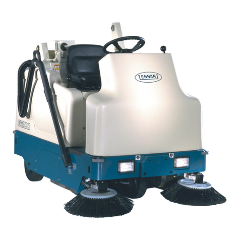
Tennant 6100 User manual

This manual is furnished with each new TENNANT Model 6100. It provides necessary operating and
preventive maintenance instructions. Read this manual completely and understand the machine before
operating or servicing it.
This machine will provide excellent service. However, the best results will be obtained at minimum costs
if:
DThe machine is operated with reasonable care.
DThe machine is maintained regularly -- per the maintenance instructions provided.
DThe machine is maintained with TENNANT supplied or approved parts.
Manual Number -- 330230
Revision: 04
Published: 9--02
CALIFORNIA PROPOSITION 65 WARNING: Engine exhaust from this product contains
chemicals known to the State of California to cause cancer, birth defects, or other
reproductive harm.
Copyright E1999, 2000, 2001, 2002 TENNANT, Printed in U.S.A.

CONTENTS
1
6100 330230 (12--00)
CONTENTS
Page
SAFETY PRECAUTIONS 2...................
OPERATION 4..............................
OPERATOR RESPONSIBILITY 4...........
MACHINE COMPONENTS 5.............
SYMBOL DEFINITIONS 6................
CONTROLS AND INSTRUMENTS 7......
OPERATION OF CONTROLS 8..........
DIRECTIONAL PEDAL 8..............
BRAKE PEDAL 9....................
PARKING BRAKE PEDAL 9...........
LARGE DEBRIS TRAP PEDAL 9.......
MAIN BRUSH LEVER 10...............
CHARGING SYSTEM LIGHT 10........
ENGINE OIL PRESSURE LIGHT 10.....
FUEL LEVEL GAUGE 11...............
VACUUM FAN/FILTER SHAKER
SWITCH 12........................
STEERING WHEEL 12................
HOURMETER 12.....................
IGNITION SWITCH 13.................
HORN BUTTON 13....................
SIDE BRUSH LEVER 13...............
OPERATING LIGHTS SWITCH
(OPTION) 14......................
OPERATING/HAZARD LIGHTS SWITCH
(OPTION) 14......................
FUSES 15............................
CIRCUIT BREAKERS 15...............
OPERATOR SEAT 16..................
ADJUSTABLE OPERATOR SEAT
(OPTION) 16......................
HOPPER 17..........................
HOW THE MACHINE WORKS 18..........
PRE-OPERATION CHECKLIST 18.........
CHANGING AN LPG FUEL TANK 20.......
STARTING THE MACHINE 22.............
OPERATION ON INCLINES 24............
SWEEPING AND BRUSH INFORMATION 25
SWEEPING 26..........................
STOP SWEEPING 28....................
STOPPING THE MACHINE 29............
EMPTYING THE HOPPER 31.............
POST-OPERATION CHECKLIST 32........
OPTIONS 33............................
QUICK MOPt33.....................
MACHINE TROUBLESHOOTING 35.......
MAINTENANCE 36.........................
MAINTENANCE CHART 36...............
LUBRICATION 38........................
ENGINE 38...........................
PROPELLING SYSTEM 38.............
STEERING GEAR CHAIN 39...........
STEERING CASTOR PIVOT BEARING 39
Page
HYDRAULICS 40........................
HYDRAULIC FLUID RESERVOIR 40....
HYDRAULIC FLUID 41................
HYDRAULIC HOSES 41...............
ENGINE 42.............................
AIR FILTER 42........................
FUEL SCREEN 43....................
FUEL LINES 43.......................
CARBURETOR 44....................
SPARK PLUGS 44....................
BATTERY 44............................
BELTS AND CHAINS 45..................
VACUUM FAN BELT 45................
MAIN BRUSH BELT 45................
HYDRAULIC PUMP BELT 46...........
JACKSHAFT BELT 46.................
PROPELLING SYSTEM 47.............
STEERING GEAR CHAIN 47............
STATIC DRAG CHAIN 47..............
DEBRIS HOPPER 48.....................
INSTANT ACCESStHOPPER FILTER 48..
REMOVING INSTANT ACCESSt
FILTER 49........................
THERMO SENTRYt53..................
BRUSHES 54..........................
MAIN BRUSH 54......................
REPLACING MAIN BRUSH 54.......
CHECKING AND ADJUSTING MAIN
BRUSH PATTERN 55............
SIDE BRUSH 57......................
REPLACING SIDE BRUSH 58.......
SIDE BRUSH GUARD 58...........
SKIRTS AND SEALS 59...............
REAR SKIRTS 59..................
SIDE SKIRTS 60...................
LARGE DEBRIS TRAP SKIRT 60....
HOPPER SEALS 60................
BRAKES AND TIRES 61..................
PUSHING, TOWING, AND TRANSPORTING
THE MACHINE 63.....................
PUSHING OR TOWING THE MACHINE 63
TRANSPORTING THE MACHINE 63.
MACHINE JACKING 65...................
STORING MACHINE 65..................
SPECIFICATIONS 66.......................
GENERAL MACHINE PERFORMANCE 66..
POWER TYPE 67........................
STEERING 67..........................
HYDRAULIC SYSTEM 67.................
BRAKING SYSTEM 67...................
TIRES 67...............................
MACHINE DIMENSIONS 68..................
INDEX 69...................................
SAFETY PRECAUTIONS
6100 330230 (9--02)
2
SAFETY PRECAUTIONS
The following symbols are used throughout this
manual as indicated in their description:
WARNING: To warn of hazards or
unsafe practices that could result in
severe personal injury or death.
FOR SAFETY: To identify actions that
must be followed for safe operation of
equipment.
The machine is suited to sweep disposable
debris. Do not use the machine other than
described in this Operator Manual. The machine
is not designed for use on public roads.
The following information signals potentially
dangerous conditions to the operator or
equipment:
WARNING: Engine emits toxic gases.
Severe respiratory damage or
asphyxiation can result. Provide
adequate ventilation. Consult with your
regulatory authorities for exposure
limits. Keep engine properly tuned.
WARNING: Brush throws debris. Stop
motor before lifting hopper.
FOR SAFETY:
1. Do not operate machine:
-- Unless trained and authorized.
-- Unless operation manual is read and
understood.
-- In flammable or explosive areas unless
designed for use in those areas.
-- In areas with possible falling objects
unless equipped with overhead guard.
2. Before starting machine:
-- Check for fuel leaks.
-- Keep sparks and open flame away
from refueling area.
-- Make sure all safety devices are in
place and operate properly.
-- Check brakes and steering for proper
operation.
3. When starting machine:
-- Keep foot on brake and directional
pedal in neutral.
4. When using machine:
-- Use brakes to stop machine.
-- Go slowly on inclines and slippery
surfaces.
-- Use care when reversing machine.
-- Do not carry riders on machine.
-- Always follow safety and traffic rules.
-- Report machine damage or faulty
operation immediately.
5. Before leaving or servicing machine:
-- Stop on level surface.
-- Set parking brake.
-- Turn off machine and remove key.
6. When servicing machine:
-- Avoid moving parts. Do not wear loose
jackets, shirts, or sleeves when
working on machine.
-- Block machine tires before jacking up
machine.
-- Jack up machine at designated
locations only. Block machine up with
jack stands.
-- Use hoist or jack that will support the
weight of the machine.
-- Wear eye and ear protection if using
pressurized air or water.
-- Disconnect battery connections before
working on machine.
-- Avoid contact with battery acid.
-- Use cardboard to locate leaking
hydraulic fluid under pressure.
-- Use Tennant supplied or equivalent
replacement parts.
7. When loading/unloading machine
onto/off truck or trailer:
-- Turn off machine.
-- Use truck or trailer that will support
the weight of the machine.
-- Use winch. Do not drive the machine
onto/off the truck or trailer unless the
load height is 380 mm (15 in) or less
from the ground.
-- Set parking brake after machine is
loaded.
-- Block machine tires.
-- Tie machine down to truck or trailer.

SAFETY PRECAUTIONS
3
6100 330230 (6--99)
The following safety labels are mounted on the
machine in the locations indicated. If these or any
labels become damaged or illegible, install a new
label in its place.
FOR SAFETY LABEL -- LOCATED ON THE
SIDE OF THE OPERATOR COMPARTMENT. FLYING DEBRIS LABEL -- LOCATED
ABOVE HOPPER.
352685
EMISSIONS LABEL -- LOCATED
BELOW CONTROL PANEL.

OPERATION
6100 330230 (6--99)
4
OPERATION
OPERATOR RESPONSIBILITY
-The operator’s responsibility is to take care
of the daily maintenance and checkups of
the machine to keep it in good working
condition. The operator must inform the
service mechanic or supervisor when the
maintenance intervals are required as stated
in the MAINTENANCE section of this
manual.
-Read this manual carefully before operating
the machine. View the operation video
supplied with the machine.
FOR SAFETY: Do not operate machine,
unless operation manual is read and
understood.
-Check the machine for shipping damage.
Check to make sure the machine is
complete per shipping instructions.
-Keep your machine regularly maintained by
following the maintenance information in this
manual. We recommend taking advantage
of a regularly scheduled service contract
from your Tennant representative.
-Order parts and supplies directly from your
authorized Tennant representative. Use the
parts manual provided when ordering parts.
-After the first 50 hours of operation, follow
the recommended daily and hourly
procedures stated in the MAINTENANCE
CHART.
07324

OPERATION
5
6100 330230 (6--99)
MACHINE COMPONENTS
B
C
D
A
E
F
H
G
I
A. Instrument panel
B. Steering wheel
C. Operator pedals
D. Operator seat
E. Engine
F. Fuel tank
G. Hopper
H. Instant Accesstfilter
I. Brush door

OPERATION
6100 330230 (6--99)
6
SYMBOL DEFINITIONS
These symbols identify controls, displays, and
features on the machine:
On Start
Off Operating lights
Main brush down Hazard light
Main brush up Engine Oil Pressure
Circuit breaker #1 Battery charging system
Circuit breaker #2 Filter shaker
Circuit breaker #3 Side brush down and on
Horn Side brush up and off
Choke

OPERATION
7
6100 330230 (6--99)
CONTROLS AND INSTRUMENTS
AD
N
O
P
E
F
BC
G
H
I
J
K
L
M
Q
A. Side brush lever
B. Vacuum fan/Filter shaker switch
C. Operating/Hazard lights switch (option)
D. Engine oil pressure light
E. Charging system light
F. Hourmeter
G. Ignition switch
H. Horn button
I. Steering wheel
J. Directional pedal
K. Main brush lever
L. Operator seat
M. Circuit breaker panel
N. Brake pedal
O. Parking brake pedal
P. Choke knob (gasoline)
Q. Large debris trap pedal

OPERATION
6100 330230 (6--99)
8
OPERATION OF CONTROLS
DIRECTIONAL PEDAL
The directional pedal controls the direction of
travel and the propelling speed of the machine.
Change the speed of the machine with the
pressure of your foot on the pedal; the harder you
press the faster the machine travels.
Use the brake pedal to stop the machine.
Forward: Press the top of the directional pedal
with the toe of your foot.
Reverse: Press the bottom of the directional pedal
with the heel of your foot.
Neutral: Take your foot off the directional pedal
and it will return to the Neutral position.
NOTE: The machine may coast when the foot is
taken off the directional pedal. Be prepared to
step on the brake pedal when removing foot from
directional pedal.

OPERATION
9
6100 330230 (6--99)
BRAKE PEDAL
The brake pedal stops the machine.
Stop: Remove your foot from the directional pedal
and let it return to the Neutral position. Step on
the brake pedal to prevent the machine from
rolling.
NOTE: Machine may roll a slight distance when
turned off. Keep foot on brake until machine stops
moving.
PARKING BRAKE PEDAL
The parking brake pedal sets and releases the
front wheel brake.
Set: Hold the brake pedal with the right foot.
Press on the parking brake pedal with the left foot
to lock the parking brake pedal in place.
FOR SAFETY: Before leaving or
servicing machine, stop on level
surface, set parking brake, turn off
machine, and remove key.
Release: Press down on the brake pedal until the
parking brake releases.
LARGE DEBRIS TRAP PEDAL
The large debris trap pedal opens the trap flap in
front of the main sweeping brush.
Open: Press on the trap pedal when sweeping up
larger debris. The flap in front of the main
sweeping brush will open.
Close: Release the pedal and the flap will close,
trapping larger debris into the hopper.

OPERATION
6100 330230 (6--99)
10
MAIN BRUSH LEVER
The main brush lever controls the position of the
main brush.
Main brush down: Pull the lever to the right and
back into the Main brush down position.
Main brush up: Push the lever up and to the left
into the Main brush up position.
CHARGING SYSTEM LIGHT
The charging system light comes on when the
alternator is not operating within the normal range;
13.5 to 14.5 V. If the light comes on, stop
operating the machine. Locate the problem and
have it corrected.
ENGINE OIL PRESSURE LIGHT
The engine oil pressure light comes on when the
engine oil pressure falls below 40kPa (5 psi). If
the light comes on, stop operating the machine.
Locate the problem and have it corrected.

OPERATION
11
6100 330230 (6--99)
FUEL LEVEL GAUGE
The fuel level gauge indicates how much fuel is
left in the fuel tank.
ENGINE CHOKE KNOB
The engine choke knob controls the engine choke
on gasoline powered machines.
On: For cold starting, pull the engine choke knob
out.
Off: Push the engine choke knob in.

OPERATION
6100 330230 (6--99)
12
VACUUM FAN/FILTER SHAKER SWITCH
The vacuum fan/filter shaker switch controls both
the vacuum fan damper and the VCStVibrating
Comb Shaker. The vacuum fan damper should be
open when sweeping dry debris, and closed when
sweeping wet debris.
Vacuum fan on: Press the top of the switch to the
vacuum fan on position for dry sweeping.
Vacuum fan off: Press the switch to the middle
vacuum fan off position for wet sweeping.
Start filter shaker: Press and hold the bottom of
the switch for eight to ten seconds.
NOTE: Excessive heat in the hopper will cause
the Thermo Sentrytto close the vacuum fan
damper. If this happens, stop the machine,
eliminate the source of heat, and reset the switch
to the vacuum fan on position.
WARNING: Brush throws debris.
Stop motor before lifting hopper.
STEERING WHEEL
The steering wheel controls the machine’s
direction. The machine is very responsive to the
steering wheel movements.
Left: Turn the steering wheel to the left.
Right: Turn the steering wheel to the right.
HOURMETER
The hourmeter records the number of hours the
machine has been operated. The hourmeter
displays the number of hours in tenths of an hour.
Use this information to determine machine
maintenance intervals.

OPERATION
13
6100 330230 (6--99)
IGNITION SWITCH
The ignition switch controls machine power and
main sweeping brush with a key.
Start: Turn the key all the way clockwise, and
release the key as soon as the engine starts. The
vacuum fan and main brush both operate while
the engine is running.
FOR SAFETY: When starting machine,
keep foot on brake and directional pedal
in neutral.
Stop: Turn the key counterclockwise.
WARNING: Brush throws debris. Stop
motor before lifting hopper.
HORN BUTTON
The horn button operates the horn.
Sound: Press the button.
SIDE BRUSH LEVER
The side brush lever controls the position and the
power of the side brush.
Side brush down and on: Pull the lever left and
forward into the Side brush down and on
position. The brush will automatically start
rotating.
Side brush up and off: Pull the lever back and to
the right into the Side brush up and off position.

OPERATION
6100 330230 (6--99)
14
OPERATING LIGHTS SWITCH (OPTION)
The operating lights switch powers on and off the
headlights and taillights option.
On: Press the top of the operating lights switch.
Off: Press the switch to the middle position.
OPERATING/HAZARD LIGHTS SWITCH
(OPTION)
The operating/hazard lights switch powers on and
off the headlights and taillights option and the
hazard light option.
Operating lights on: Press the top of the
operating/hazard lights switch.
Operating/Hazard lights on: Press the bottom of
the operating/hazard lights switch.
Off: Press the operating/hazard lights switch to
the middle off position.

OPERATION
15
6100 330230 (12--99)
FUSES
Fuses are one-time protection devices designed
to stop the flow of current in the event of a circuit
overload. Never substitute higher value fuses than
specified.
The fuse is located behind the circuit breaker
panel.
Fuse Rating Circuit Protected
FU-1 40 A Main
CIRCUIT BREAKERS
The circuit breakers are resettable electrical
circuit protection devices. Their design stops the
flow of current in the event of a circuit overload.
Once a circuit breaker is tripped, it must be reset
manually. Press the reset button after the breaker
has cooled down. The circuit breakers will not
reset until they have had a chance to cool down.
If the overload that caused the circuit breaker to
trip is still there, the circuit breaker will continue to
stop current flow until the problem is corrected.
Circuit breakers 1 through 3 are located above the
foot pedals in the circuit breaker panel.
The chart lists the circuit breakers and the
electrical components they protect.
Circuit Breaker Rating Circuit Protected
CB-1 15 A Horn / Back up alrm
CB-2 15 A Filter shaker
CB-3 10 A Main
1
3
2

OPERATION
6100 330230 (6--99)
16
OPERATOR SEAT
The operator seat is a stationary fixed back style.
ADJUSTABLE OPERATOR SEAT (OPTION)
This operator seat is a fixed back style with a
forward-backward adjustment.
Adjust: Pull the lever in, slide the seat backward
or forward to the desired position, and release the
lever to lock the seat in place.

OPERATION
17
6100 330230 (6--99)
HOPPER
The hopper is located in the rear of the machine
under the hopper filter. The hopper rolls in and out
of position and rests in grooves that hold the
hopper in place.
The hopper is held in operating position with a
retaining clip.
NOTE: Check that the hopper retaining clip is
securely in place each time before operating
machine.
Remove hopper: Turn the hopper retaining clip to
the horizontal open position. Lift up on the hopper
handle. Pull the hopper back out of the machine.
Replace hopper: Push hopper back into position
under hopper filter. Secure hopper in position with
hopper retaining clip.

OPERATION
6100 330230 (6--99)
18
HOW THE MACHINE WORKS
The steering wheel controls the direction of
machine travel. The directional pedal controls the
speed and forward/reverse direction. The brake
pedal slows and stops the machine.
The side brush sweeps debris into the path of the
main sweeping brush. The main brush sweeps
debris from the floor into the hopper. The large
debris trap pedal opens and closes the large
debris trap, trapping large debris into the hopper.
The vacuum system pulls dust and air into the
hopper through the Instant Accesstfilter.
When sweeping is finished, clean the Instant
Accesstfilter and empty the hopper.
PRE-OPERATION CHECKLIST
-Check under the machine for leaks
(fuel, oil or hydraulic fluid).
-Check the engine air filter.
Other manuals for 6100
5
Table of contents
Other Tennant Floor Machine manuals

Tennant
Tennant 235E User manual

Tennant
Tennant 611363 5100 User manual

Tennant
Tennant 2510 Product manual

Tennant
Tennant 8410 User manual

Tennant
Tennant 6600 User manual

Tennant
Tennant 1510 Product manual

Tennant
Tennant 1210 Manual

Tennant
Tennant 810 Gas User manual

Tennant
Tennant 608808 Product manual

Tennant
Tennant 2300 Product manual

Tennant
Tennant 1240 User manual

Tennant
Tennant SM15040 Product manual

Tennant
Tennant 6400E User manual

Tennant
Tennant 340513 Training manual

Tennant
Tennant M20 User manual

Tennant
Tennant 5500 Complete Product manual

Tennant
Tennant S30 User manual

Tennant
Tennant 1465 User manual

Tennant
Tennant 613087 User manual

Tennant
Tennant 1240 Product manual