manuals.online logo
Brands
  1. Home
  2. •
  3. Brands
  4. •
  5. Tennant
  6. •
  7. Floor Machine
  8. •
  9. Tennant ATLV 4300 Training manual

Tennant ATLV 4300 Training manual

Other manuals for ATLV 4300

6

Other Tennant Floor Machine manuals

Tennant 2370 User manual

Tennant

Tennant 2370 User manual

Tennant 1100 Product manual

Tennant

Tennant 1100 Product manual

Tennant SweepSmart S20 ELECTRIC Training manual

Tennant

Tennant SweepSmart S20 ELECTRIC Training manual

Tennant i-team i-mop xxl User manual

Tennant

Tennant i-team i-mop xxl User manual

Tennant T290 User manual

Tennant

Tennant T290 User manual

Tennant 5500 Complete User manual

Tennant

Tennant 5500 Complete User manual

Tennant 800D User manual

Tennant

Tennant 800D User manual

Tennant ATLV 4300 Training manual

Tennant

Tennant ATLV 4300 Training manual

Tennant 8210D User manual

Tennant

Tennant 8210D User manual

Tennant 235E User manual

Tennant

Tennant 235E User manual

Tennant M17 Series Training manual

Tennant

Tennant M17 Series Training manual

Tennant CS5 User manual

Tennant

Tennant CS5 User manual

Tennant 5200 Product manual

Tennant

Tennant 5200 Product manual

Tennant B10 Operating and installation instructions

Tennant

Tennant B10 Operating and installation instructions

Tennant 355 User manual

Tennant

Tennant 355 User manual

Tennant 5200 Product manual

Tennant

Tennant 5200 Product manual

Tennant MM267 User manual

Tennant

Tennant MM267 User manual

Tennant B1 Series Product manual

Tennant

Tennant B1 Series Product manual

Tennant 2260 Product manual

Tennant

Tennant 2260 Product manual

Tennant B10 User manual

Tennant

Tennant B10 User manual

Tennant 8210 User manual

Tennant

Tennant 8210 User manual

Tennant 1186E User manual

Tennant

Tennant 1186E User manual

Tennant 810 LPG User manual

Tennant

Tennant 810 LPG User manual

Tennant 5200 Product manual

Tennant

Tennant 5200 Product manual

Popular Floor Machine manuals by other brands

Nilfisk-Advance Advance SC370 17B Instructions for use

Nilfisk-Advance

Nilfisk-Advance Advance SC370 17B Instructions for use

BETCO PB24 Operator's manual

BETCO

BETCO PB24 Operator's manual

Numatic ET 4045 Owner's instructions

Numatic

Numatic ET 4045 Owner's instructions

Mytee 8070 Mytee-Lite instructions

Mytee

Mytee 8070 Mytee-Lite instructions

Kärcher B 140 R manual

Kärcher

Kärcher B 140 R manual

Nilfisk-Advance SW 750 Service manual

Nilfisk-Advance

Nilfisk-Advance SW 750 Service manual

IPC CT51-71 BT quick guide

IPC

IPC CT51-71 BT quick guide

Tornado Marathon 2000 98190 Operation & maintenance manual

Tornado

Tornado Marathon 2000 98190 Operation & maintenance manual

Windsor ADMIRAL Admiral 8 Specifications

Windsor

Windsor ADMIRAL Admiral 8 Specifications

Numatic TTB 1117/100 Owner's instructions

Numatic

Numatic TTB 1117/100 Owner's instructions

Nobles Frontier Operator and parts manual

Nobles

Nobles Frontier Operator and parts manual

lavina 21-X user manual

lavina

lavina 21-X user manual

KENT Edge 28B Service manual

KENT

KENT Edge 28B Service manual

Windsor BDP 51/2000C operating instructions

Windsor

Windsor BDP 51/2000C operating instructions

Nilfisk-Advance Warrior 34RST How-to guide

Nilfisk-Advance

Nilfisk-Advance Warrior 34RST How-to guide

HAWK ENTERPRISES HP1513-180BRUTE manual

HAWK ENTERPRISES

HAWK ENTERPRISES HP1513-180BRUTE manual

Triple S Ace 26T1 user guide

Triple S

Triple S Ace 26T1 user guide

Nobles 612215 - 2401 Operator and parts manual

Nobles

Nobles 612215 - 2401 Operator and parts manual

manuals.online logo
manuals.online logoBrands
  • About & Mission
  • Contact us
  • Privacy Policy
  • Terms and Conditions

Copyright 2025 Manuals.Online. All Rights Reserved.

IB 340133 (10-02) 1
No. 340133
Machine: ATLV 4300
Published: 10-02
Rev. 07
INSTRUCTION BULLETIN
NOTE: DO NOT DISCARD the Parts List from the Instruction Bulletin. Place the Parts
List in the appropriate place in your machine manual for future reference.
Retaining the Parts List will make it easier to reorder individual parts and will
save you the cost of ordering an entire kit.
NOTE: Numbers in parenthesis ( ) are reference numbers for parts listed in Bill of Materials.
Installation instructions for kit number 367613
DESCRIPTION:
This kit contains the parts needed to install/replace a dust filter kit option on the model ATLV
4300 Litter Vacuum.
Please follow step-by-step instructions.
SPECIAL TOOLS / CONSIDERATIONS: Hand Drill and Following Drill Bits: 13/64 [5.2 mm],
19/64 [7.5 mm], and 11/32 [8.7 mm]
(Estimated time to complete: 3 hours)
PREPARATION:
(Refer to FIG. 1 thru 9)
1. Park machine on a clean level work surface.
FOR SAFETY: Before leaving or servicing machine,
stop on level surface and set parking brake.
Then turn off machine and remove key.
2. Disconnect battery cables from the machine.
WARNING: Always disconnect battery cables
from machine before working on electrical
components.
3. Remove the filter bag and vacuum fan exhaust
plate from the vacuum fan housing.
WARNING: Spinning fan. Stop engine
before opening debris canister.
4. Open and lower the debris canister. Remove any
garbage bags or liners from the debris canister.
IB 340133 (10-02)2
SPRING MOUNTING PLATE INSTALLATION:
(Refer to FIG. 1 thru 7)
Note: Spring eyelet holes may be predrilled on some
machines..
1. Mark and drill two 19/64 [7.5 mm] holes for bolt eyelet
installation on the machine frame, beneath the debris
hopper as shown in Fig. 2. (Refer to FIG. 2, 5 and 7)
2. Install the two bolt eyes (11) with hex nuts (12) and
nyloc nuts (13). Connect one end of the tension
springs (42) to each of the bolt eyes (49).
(Refer to FIG. 5 and 7)
3. Disconnect and remove the debris cannister cables,
canister cable sleeves and mounting hardware on the
debris canister.
4. Slip the canister cables onto the new sleeves (8), then
loosely mount the spring mounting plates (5), sleeves
(8), and canister cables to the lower front corners of
the hopper with hex screws (18), and washers (7).
(Refer to FIG. 5 and 7)
5. Rotate the spring mounting plates (5), until centered in
the corner of the canister. Then, using the plates as
templates, mark and drill two 11/32 [8.7 mm] mounting
holes in the lower front corner, on each side of the
hopper. (Refer to FIG. 5 and 7)
6. Using the new mounting holes, assemble the spring
mounting plates (5) to the canister with backing strips
(6), and hex nuts (10). Tighten all mounting hardware.
(Refer to FIG. 5 and 7)
7. Connect the open end of the tension springs (4) to the
open tabs on the spring mounting plates (5). Close the
debris hopper, and place it back in the upright
position. (Refer to FIG. 5 and 7)
5
6
10
IB 340133 (10-02) 3
PLASTIC FILTER HOUSING ASSEMBLY AND INSTALLATION:
1. Clean off a large table or work surface. Place the new
plastic filter housing (1) on the flat surface, with the
back side of the plastic filter housing (1) facing down.
(Refer to FIG. 6)
2. Push the bulb seal (17) onto the edge, around the
entire bottom opening of the filter housing.
(Refer to FIG. 6)
3. Mount the hinges (16) to the bottom of the plastic
filter housing (1) with screws (10) and washers (4).
Leave the hardware loose for the time being.
(Refer to FIG. 6)
4. Mount the latch brackets (14) and door hinge (9), to
the inside of the plastic filter housing (1) with screws
(10), (15) and washers (4). (Refer to FIG. 6)
5. Install the bypass door latches (21) and latch pawls
(22) to the bypass door (18) as shown.
(Refer to FIG 6)
6. Mount the bypass door (18) onto the door hinges (16)
with the nylon bushings (19). Secure the door onto the
hinges with the cotter pins (20). (Refer to FIG 6)
7. Close and latch the bypass door (18). Install the door
stop bolts (23) and nuts (24) from the inside of the
plastic filter housing (1). (Refer to FIG. 6)
8. Open and close the bypass door (18) a few times.
Adjust the latch pawl (22) location as necessary to
compress the door seal (17) when the door is closed
and latched. (Refer to FIG. 6)
9. Remove the debris canister latches, flip them 180°,
then remount. (Refer to FIG. 9)
10.(Machines S.N. 000000 -- 001741) Using the upper
(27) and lower (28) filter housing mounting brackets
as templates, mark and drill sixteen mounting holes
in the debris hopper according to the dimensions in
figure 5. (Refer to FIG. 3)
11. (Machines S.N. 000000 -- 001741) Mount the upper
(27) and lower (28) filter housing mounting brackets to
the hopper with pop rivets (8) and washers (29). Install
rivets from the inside of the debris hopper.
(Refer to FIG. 6)
17
22 21
17 18
IB 340133 (10-02)4
12.(Machines S.N. 000000 -- 001741) Mount the plastic
filter housing (1) to the mounting brackets, (27) and
(28), with hex screws (31) and mounting strips (30).
(Refer to FIG. 6)
13.(Machines S.N. 000000 -- 001741) Mount the support
brackets (35) and (36) to each side of the plastic filter
housing (1) with hex screws (23). (Refer to FIG. 6)
(Machines S.N. 001741 -- xxxxxx) Mount the support
brackets (42) and (43) to each side of the plastic filter
housing (1) with hex screws (23). (Refer to FIG. 6)
14.(Machines S.N. 000000 -- 001741) Using the support
brackets (35) and (36) as templates, mark and drill
two 11/32 [8.73 mm] mounting holes for the support
brackets in each side of the debris hopper.
(Refer to FIG. 6)
(Machines S.N. 001741 -- xxxxxx) Using the support
brackets (42) and (43) as templates, mark and drill
two 11/32 [8.73 mm] mounting holes for the support
brackets in each side of the debris hopper.
(Refer to FIG. 6)
15.(Machines S.N. 000000 -- 001741) Secure the support
brackets to each side of the debris hopper with
backing strips (37) and lock nuts (24).
(Refer to FIG. 6)
24
37
IB 340133 (10-02) 5
16.(Machines S.N. 000000 -- 001741) Mount the door
latches (6) to the sides of the filter housing (1) with
pop rivets (8) and washers (29).
(Refer to FIG. 6)
(Machines S.N. 001741 -- xxxxxx) Mount the door
latches (40) to the sides of the filter housing (1) with
pop rivets (41) and washers (29).
(Refer to FIG. 6)
Note: Install the rivets from the inside of the filter housing.
17.(Machines S.N. 000000 -- 001741) Mount the door
latch tabs to the right hand (2) and left hand (3) cable
brackets with pop rivets (7). If the latch keepers are
mounted backwards, latches will not close properly.
(Refer to FIG. 6)
(Machines S.N. 001741 -- xxxxxx) Mount the door
latch tabs to the right hand and left hand cable
brackets with pop rivets (41). If the latch keepers are
mounted backwards, latches will not close properly.
(Refer to FIG. 6)
18.Loosely mount the right hand (2) and left hand (3)
cable brackets to the filter door (32) with washers (4)
and nyloc nuts (5). (Refer to FIG. 6)
19.Mount one end of each filter housing cable (11) to
each side of the plastic filter housing (1) with hex
screws (13) sleeves (12), washers (4) and
lock nuts (5). (Refer to FIG. 6)
20.Install the filter door (32) onto the door hinge (9), in
the plastic filter housing (1). Close the filter door (32)
and secure it with the door latches (6).
(Refer to FIG. 6)
21.Connect the open ends of each filter housing cable
to the cable brackets on each side of the filter door
(32), with sleeves (12), washers (4) and lock nuts (5).
(Refer to FIG. 6)
22.Open the filter door, and insert the filter panel (33)
with the gasket side facing the housing, and filter
pleats vertical. Close the filter door (32) and secure
the filter (33) in the plastic filter housing (1) with
latches. Tighten the nuts (5) on the right hand (2) and
left hand (3) cable brackets.
Adjust the door hinge (9) and latches if necessary to
achieve gasket compression on the filter panel (33).
Tighten all plastic filter housing hardware when
finished adjusting all the filter door mounting
hardware. (Refer to FIG. 6)
IB 340133 (10-02)6
FILTER HOUSING DUCT INSTALLATION:
1. Mount the vacuum exhaust plate gasket (15) to the
new vacuum exhaust plate (14), then attach the
vacuum exhaust plate (14) to the vacuum fan housing
with pan screws (16) and washers (17).
(Refer to FIG. 5 and 7)
2. Insert the new filter bag (9) through the top opening of
the filter housing (1). Place the filter bag’s elastic band
over the lip of the filter housing (1).
(Refer to FIG. 5 and 7)
Note: The filter bag is now inserted inside the filter housing.
3. Mount one end of the filter inlet duct (1) over the
vacuum exhaust plate (14) with the worm drive
clamps (2). (Refer to FIG. 5 and 7)
Note: The filter bag is now kept in the filter housing, and no
longer mounts to the vacuum fan housing.
4. Place the bottom end of the filter inlet duct (1) over the
opening in the plastic filter housing. Check that the
inlet duct (1), and the retaining clamp (3) fit over the
lip of the plastic housing, and the filter bag (9). Secure
the filter inlet duct (1) in place with the draw latch on
the retaining clamp (3).
(Refer to FIG. 5 and 7)
5. Mount the label mounting bracket (25) to the plastic
filter housing (1) with screws (23), washers (26) and
lock nuts (24). Place warning decals 367667 and
367668 from the label kit onto the label mounting
bracket. Discard the rest of the label kit.
(Refer to FIG. 6)
6. If the machine is equipped with a slow--moving vehicle
sign, mount the SMV label bracket (34) to the filter
door (32) with hex screws, (13) and washers (4).
Attach the sign to the bracket (34). (Refer to FIG. 6)
7. Open the debris canister and replace the liners and
garbage bags. Close and latch the canister.
8. Start the machine and check the vacuum dust filter kit
for proper operation.
IB 340133 (10-02) 7
Remove old filter bag
(new filter bag will
mount inside the new
plastic filter housing)
Remove old vacuum
exhaust plate
FIG. 1 -- FILTER BAG AND PLATE REMOVAL
.50
.50 .50
.50
∅
∅∅
∅19/64 (.297) (2)
FIG. 2 -- HOLE LOCATIONS FOR SPRING EYELET MOUNTINGS
IB 340133 (10-02)8
368198
∅
∅∅
∅13/64 (16)
(5.16)
21/2(2)
(63.50)
36.79 REF
(934.47)
87/8(2)
(225.48)
87/8(2)
(225.48)
31/4(2)
(82.55)
31/4(2)
(82.55)
3/8 (2)
(9.52)
3/8 (2)
(9.52)
2 15/32 (4)
(62.86)
25.978 (4)
(659.84)
2 27/32 (4)
(72.39)
5 13/16 (4)
(147.62)
21/2(2)
(63.50)
FIG. 3 -- MOUNTING BRACKET HOLE DIMENSIONS
IB 340133 (10-02) 9
1
5
10
23
4
13
12
12
11 12 13
14
16
17
22
12
13
24
21
8
6
723
22
12
13
15
4
14
8
6
7
20
19
18
4
3
27
28
25
12
26
31
32
33
30
31
29
2
8
35
34
36
8
33
6
33
6
33
FIG. 4 -- Dust Filter Housing Group (Serial Number 000000--001535)
IB 340133 (10-02)10
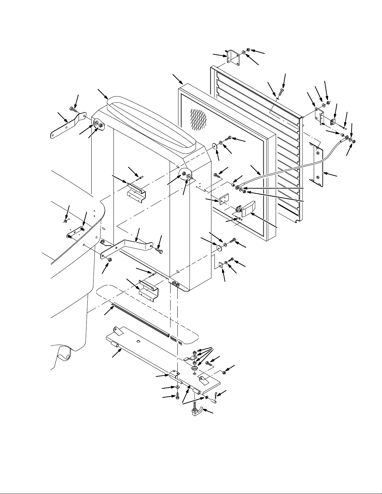
BILL OF MATERIALS FOR DUST FILTER HOUSING GROUP (S.N. 000000--001535)
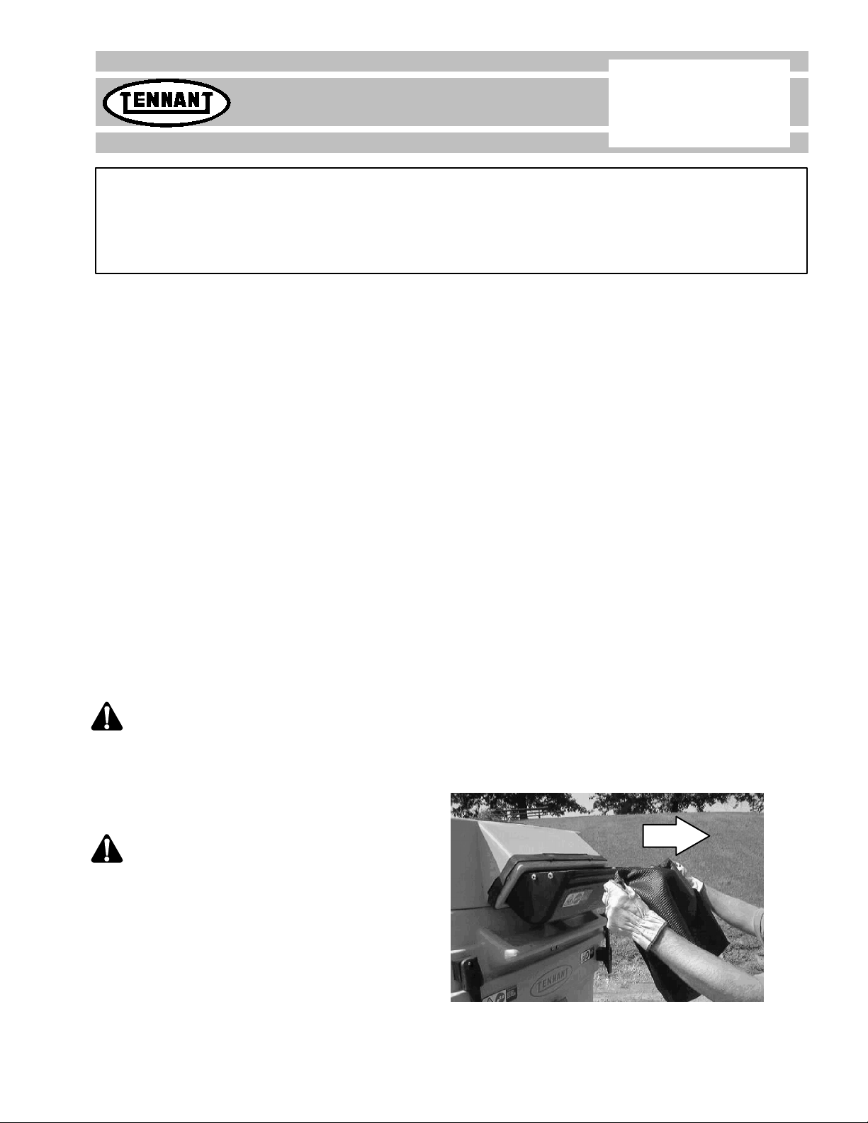
NOTE: Dust Filter Kit, Tennant Part Number 367613 includes Fig. 4 and Fig. 5
Ref.
Tennant
Part No.
Machine Serial
Number Description Qty.
1368405 (000000--001535 )Housing Assy, Dust Filter 1
2 367985 (000000--001535 ) Bracket, Mtg, Upper 2
3 367982 (000000--001535 ) Bracket, Mtg, Lower 2
4 80218 (000000--001535 ) Rivet, Pop .196dx.76x38dhd 22
5 08793 (000000--001535 ) Washer 16
601685 (000000--001535 )Washer, Flat, .31 Ss 8
7 30013 (000000--001535 ) Washer, Flat, .31 Fender 4
8 09010 (000000--001535 ) Screw, Hex, M08--1.25 X 25, Ss 6
9 367994 (000000--001535 ) Door, Filter, Mtg 1
10 368221 (000000--001535 ) Bracket, Mtg, Rh 1
11 368254 (000000--001535 )Bracket, Mtg, Lh 1
12 01684 (000000--001535 ) Washer, Flat, .25 Ss 16
13 08712 (000000--001535 ) Nut, Hex, Lock, M06--1.0, Nl,Ss 8
14 368586 (000000--001535 ) Kit, Ci, Filter Latch 1
15 368253 (000000--001535 ) Plate, Latch (Repl. by 368586) 2
16 87821 (000000--001535 )Rivet, Pop 4
17 368542 (000000--001535 ) Filter Panel, [In A Box] 1
18 368318 (000000--001535 ) Guide, Centering, Door 2
19 01683 (000000--001535 ) Washer, Flat, #10 Ss 2
20 55845 (000000--001535 ) Screw, Hex, Fmg, M05--0.8 X 16 2
21 19676 (000000--001535 )Cable, Lanyard 2
22 80491 (000000--001535 ) Sleeve 4
23 15678 (000000--001535 ) Screw, Hex, M06--1.0 X 16, Ss 6
24 368263 (000000--001535 ) Bracket, Mtg, Label 1
25 368341 (000000--001535 ) Hinge Wldt, Door 2
26 08716 (000000--001535 )Screw, Hex, M06--1.0 X 20, Ss 4
27 368340 (000000--001535 ) Seal, Door 1
28 368339 (000000--001535 ) Door Wldt, By--Pass 1
29 15877 (000000--001535 ) Bearing, Flange 4
30 08178 (000000--001535 ) Pin, Cotter 2
31 65695 (000000--001535 )Latch 2
32 09740 (000000--001535 ) Screw, Hex, M08--1.25 X 20, Ss 2
33 08713 (000000--001535 ) Nut, Hex, Lock, M08--1.25,Nl,Ss 8
34 368222 (000000--001535 ) Strip, Backing 2
35 368402 (000000--001535 ) Bracket, Support, Rh 1
36 368403 (000000--001535 )Bracket, Support, Lh 1