Tennant T5e ec-H2O 9006828 User manual

T5e ec--H2O Kit
KIT NO. 9006828 Page1of9
t
9006829 Rev. 00 (12--09) Tennant Company Customer Service: (800) 553--8033 or (763) 513--2850
This kit includes the parts needed to convert a standard model over to an ec--H2Otmodel.
INSTALLATION INSTRUCTIONS:
Installation Time: 4--6 Hours
Special Tools Required: None
PREPARE MACHINE FOR KIT INSTALL:
1. Drain the solution and recovery tanks.
2. Park the machine on a level surface, lower the
scrub head and remove the key.
3. Remove the scrub head assembly from the
machine(Figure1).
FOR SAFETY: Before removing the scrub head
assembly, disconnect the battery cables.
Disk Model
shown
Fig. 1
4. Remove the batteries from the machine
(Figure 2).
FOR SAFETY: When handling batteries, wear pro-
tective gloves and eye protection. Avoid contact
with battery acid.
Fig. 2
INSTALL ec- H2O WIRE HARNESS:
1. Remove the cover the from the circuit breaker box
and install ec--H2O wire harness [p/n 1055447]
(Figure 3).
Circuit
Breaker
Cover
Fig. 3
2. Starting from inside the circuit breaker box,
connect the following ec--H2O harness wires as
described in steps 3, 4 and 5 (Figure 4).
Relay
[p/n 1012216]
Red 1z
Black 13u/13T/13z/13s
Fig. 4
3. Connect red wire (1z) to the brush contactor
terminal and the black wires (13u/13T/13z/13s) to
the ground stud (Figure 5).
Red 1z
Black 13u/13T/13z/13s
Fig. 5
Home
Find...
Go To..

T5e ec- H2O Kit
INSTALLATION INSTRUCTIONS -- Continued
Page2of9
KIT NO. 9006828
9006829 Rev. 00 (12--09) Tennant Company Customer Service: (800) 553--8033 or (763) 513--2850
4. Using Nut [p/n 09739], attach Relay [p/n 1012216]
to the mounting stud located inside the circuit
breaker box (Figure 6). Connect ec--H2O harness
wiretorelay(See Figure 4 for relay reference).
Relay
mounting
stud
Fig. 6
5. Connect ec--H2O harness connector to the open
connector located inside the circuit breaker box
(Figure 7).
ec--H2O Harness
Connector
Fig. 7
6. Route the following ec--H2O harness wires to
control console as described in steps 7 and 8
(Figure 8).
To LED Light
To ec--H2O
on/off Switch
Fig. 8
7. Remove the vacuum motor cover (Figure 9).
Vacuum
motor cover
Fig. 9
8. Remove the vacuum motor and route ec--H2O
harness wires (Figure 8) through the recovery
tank harness hole and into the control console
(Figure 10). Replace vacuum motor and cover.
ec--H2O
Harness
Wires
To Control
Console
Fig. 10
9. Remove factory installed clamps and replace with
larger cable clamps [p/n 606697] to secure
ec--H2O harness (Figure 11).
Clamps
[p/n 606697]
Fig. 11
Home
Find...
Go To..

Page3of9
KIT NO. 9006828
T5e ec- H2O Kit
INSTALLATION INSTRUCTIONS -- Continued
9006829 Rev. 00 (12--09) Tennant Company Customer Service: (800) 553--8033 or (763) 513--2850
10. Route the following ec--H2O harness wires
(Figure 12) as described in step 11.
To Pressure
Switch
To Horn
To Pump
Fig. 12
11. Route the above ec--H2O harness wires to the
scrub head assembly as shown (Figure 13).
Route
Harness
Fig. 13
12. Arrange the ec--H2O wire harness within the
circuit breaker box as shown (Figure 14).
Harness
Wires (C)
To Control
Console
Fig. 14
12. Replace circuit breaker box cover (Figure 15).
Fig. 15
INSTALL THE ec- H2O CONTROL CONSOLE
COMPONENTS:
1. Remove the upper control panel from the control
console and locate the routed ec--H2O harness
wires (Figure 16).
Fig. 16
2. Remove the components from the upper control
panel (take note of wire connections before
removing). Using new panel [p/n 1041719] and label
[p/n 1050010], re--install components (Figure 17).
Install ec--H2O LED light [p/n 1041822] as shown.
LED Light
[p/n 1041822]
Remove components
New Panel [p/n 1041719]
New Lable [p/n 1050010]
Fig. 17
Home
Find...
Go To..

T5e ec- H2O Kit
INSTALLATION INSTRUCTIONS -- Continued
Page4of9
KIT NO. 9006828
9006829 Rev. 00 (12--09) Tennant Company Customer Service: (800) 553--8033 or (763) 513--2850
3. Connect the routed ec--H2O harness wires to the
LED light (GRAY to RED, GRN to GRN and BLK to
BLK) (Figure 18).
ec--H2O
LED Light
ec--H2O
Harness
Wires
Fig. 18
4. Remove the lower control panel from console
(Figure 19).
Fig. 19
5. Remove the components from the lower panel (take
note of wire connections before removing).Using
new lower panel [p/n 1024111] and label
[p/n 1050011], re--install components (Figure 20).
Lower Panel [p/n 1024111]
Label [p/n 1050011]
Fig. 20
6. Install the ec--H2O on/off switch [p/n 130787] as
shown (Figure 21).
ec--H2O on/off Switch
[p/n 130787]
Take note of
switch orientation
Fig. 21
6. Route the remaining console wires from the
ec--H2O wire harness to the lower control panel
(Figure 22).
ec--H2O
Harness
Wires
Fig. 22
7. Disconnect wire 14 yellow from key switch
(Figure 23).
14 Yellow
Fig. 23
8. Connect ec--H2O harness wires 94/94A yellow to
key switch as shown (Figure 24). Connect 94B
yellow to wire 14 yellow.
94/94A
Yellow
94B Yellow
14 Yellow
Fig. 24
Home
Find...
Go To..

Page5of9
KIT NO. 9006828
T5e ec- H2O Kit
INSTALLATION INSTRUCTIONS -- Continued
9006829 Rev. 00 (12--09) Tennant Company Customer Service: (800) 553--8033 or (763) 513--2850
9. Connect diode [p/n 222290] to the ec--H2O harness
as shown (Figure 25).
Diode
[p/n 222290
Fig. 25
10. Within the lower control console wiring, locate and
remove Blue Jumper Wire 36 from wires 8/8A Gray
and 6/16 Blue and discard (Figure 26).
Blue
Jumper
Wire 36
Fig. 26
11. Connect wires 8/8A Gray, 6/16 Blue and 30 Tan to
the ec--H2O on/off Switch as shown (Figure 27).
8/8A Gray
6/16 Blue
30 Tan
Fig. 27
12. Replace the lower and upper control panels.
INSTALL THE ec- H2O MODULE:
1. Cut the two ec--H2O module hoses to the specified
length and set the DIP switch settings accordingly
(Figure 28). Install the DIP switch grommet
[p/n 1054776].
26 in
66 cm
Cut
DIP Switch Setting
32”/800mm
Cylindrical Model
24”/600mm Disk Model
26”/650mm
Cylindrical Model
28”/700mm &
32”/800mm Disk Models
123456
123456
123456
123456
Grommet [p/n 1054776]
Top View of Module
DIP
Switch
ec--H2O
Module
[1048395]
Fig. 28
2. Using two m6x1.00x16 sems screws [p/n 1034731],
attach the ec--H2O module mounting bracket
[p/n 1045965] to the ec--H2O module as shown
(Figure 29).
Module
Mounting
Bracket
[p/n 1045965]
Screw (2)
[p/n 1034731]
Fig. 29
Home
Find...
Go To..

T5e ec- H2O Kit
INSTALLATION INSTRUCTIONS -- Continued
Page6of9
KIT NO. 9006828
9006829 Rev. 00 (12--09) Tennant Company Customer Service: (800) 553--8033 or (763) 513--2850
3. Plug the the ec--H2O wire harness module
connector into the module (Figure 30).
ec--H2O
Wire
Harness
Fig. 30
4. Route the module hoses to the scrub head area as
shown (Figure 30).
Module
hoses
Fig. 31
5. Using two m6x1.00x16 sems screws [p/n 1034731],
mount the ec--H2O module to the machine as
shown (Figure 32).
Screw (2)
[p/n 1034731]
Fig. 32
INSTALL ec- H2O SOLUTION SYSTEM:
1. On a level non--marring surface carefully lay the
machine on its right side and remove the
squeegee mount bracket (Figure 33).
Remove
Squeegee
Mount
Bracket
Fig. 33
2. Assemble the pump assembly as shown (Figure
34). Use a thread sealer tape on all fittings.
2
1
3
46
5
7
10
12
11
9
8
Fig. 34
Ref p/n. Description Qty.
1 1042495 Pump, Soltn, Ele, 24Vdc, 35psi 1
2 1023463 Bracket, Mtg, Pump 1
3 43555 Clamp, Hose, Wormdrive 2
4 1017532 Fitting, Plstc, E90, BM08/PM06 1
5 611259 Hose, Pvc, Clear, 0.50ID 0.75OD x 9.75” 1
6 607776 Clamp, Hose, Wire, .73--.77 1
7 601483 Fitting, Brs, Tee, PF06/PF06/PM06, Run 1
8 24698 Fitting, Brs, Str, PF02/PM06 1
9 1017386 Valve, Vent, Air, Float Type 1
10 1005630 Fitting, Plstc, E90, BM06/PM06, Nyl 1
11 54333 Clamp, Hose, Wormdrive, 0.31--0.88D, .31W 1
12 376720 Hose, Pvc, Brd, 0.38ID 0.60OD x 9.0” 1
Pump Assembly Parts List (Figure 34)
3. Mount the pump assembly to the machine frame
with two M6x1.00x16 hex screws [p/n 1034731]
as shown (Figure 35). Route the two pump hoses
as shown.
2--Hex Screws
(p/n 1034731)
Pump Hoses
Fig. 35
Home
Find...
Go To..

Page7of9
KIT NO. 9006828
T5e ec- H2O Kit
INSTALLATION INSTRUCTIONS -- Continued
9006829 Rev. 00 (12--09) Tennant Company Customer Service: (800) 553--8033 or (763) 513--2850
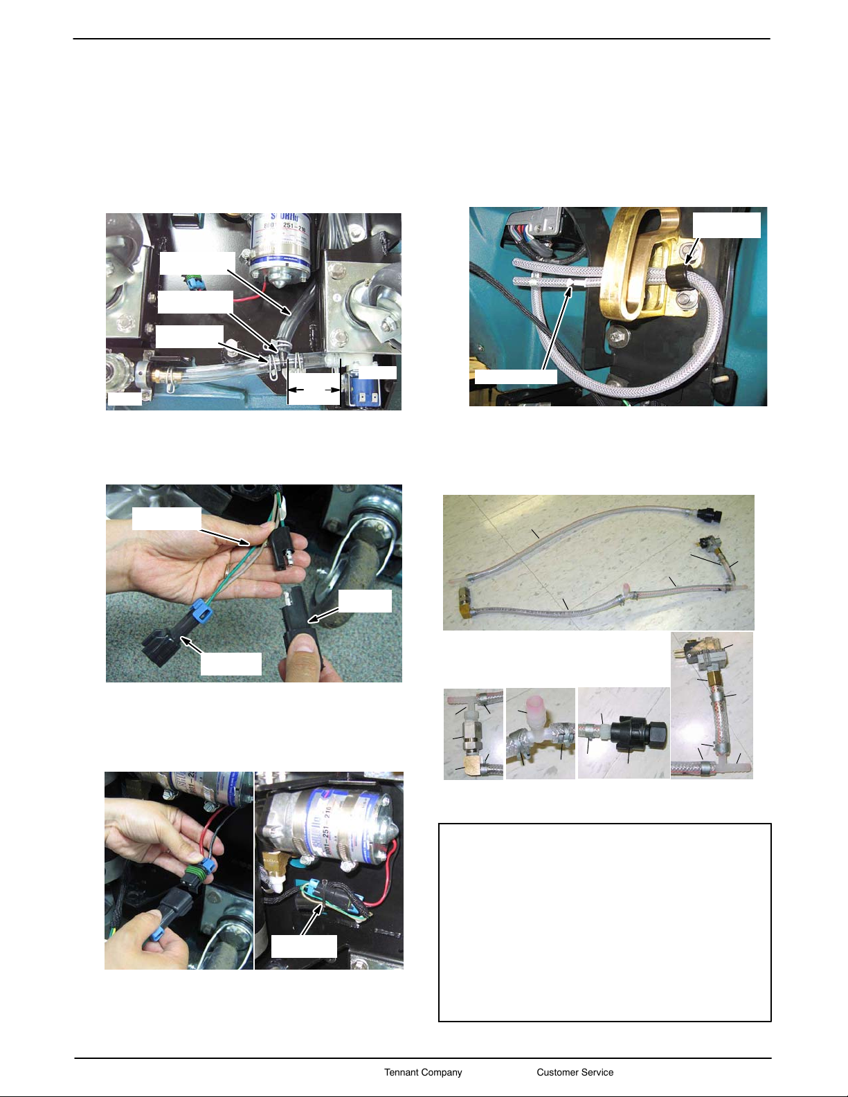
4. Cut the solution hose located between the valve
and filter as described below (Fig. 36). Using the
black T--fitting [p/n 63245--1] and 3 wire clamps
[p/n 607776], connect the ec--H2O pump intake
hose to cut hose as shown (Figure 36).
Cut
3in
7.6 cm
ec--H2O Pump
Intake Hose
Add T--Fitting
[p/n 63245--1]
Clamp (3)
[p/n 607776]
Filter
Valve
Fig. 36
5. Connect the capacitor plug [p/n 1040868] to the
ec--H2O wire harness that was routed down to the
scrub head area (Figure 37).
Capacitor
Plug
ec--H2O Wire
Harness
To ec--H2O
Pump
Fig. 37
6. Plug the pump wire connector into the ec--H2O
wire harness. Secure the wire connection and
capacitor plug to the machine frame with a
wire--tie as shown (Figure 38).
Wire--Tie
[p/n 130773]
Fig. 38
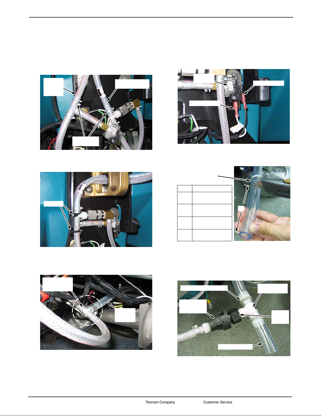
7. Replace the squeegee mount bracket (Figure 31)
and carefully stand the machine upright.
8. Install clamp [p/n 69234] and route the two
ec--H2O module hoses as shown (Figure 39).
Module Hoses
Clamp
[p/n 69234]
Fig. 39
9. Cut the 4 ft braided hose [p/n 578227000] into the
specified hose lengths as described (ref. 1, 2, 3 &
4), then assemble the following parts as shown
(Figure 40). Use thread sealer tape on all fittings.
6
7
5
2
9
A
A) B) C)
D)
B
D
C
1
3
4
8
11
8
8
810
13
14
12
8
8
8
Detail
21”/53.3 cm
11”/28 cm
8”/20.3 cm
2.5”/6.4cm
To pumpTo module
outlet hose
To module
intake hose
Fig. 40
Ref p/n. Description Qty.
1 578227000 Hose, Pvc, Brd, .25ID x .44OD x 21.00 1
2 578227000 Hose, Pvc, Brd, .25ID x .44OD x 11.00 1
3 578227000 Hose, Pvc, Brd, .25ID x .44OD x 8.00 1
4 578227000 Hose, Pvc, Brd, .25ID x .44OD x 2.50 1
5 607306 Fitting, Plstc, Tee, BM04/BM04/PM04, Br 1
6 1044790 Check Valve 1
7 1028773 Fitting, Brs Elbow 90, BM04/PF04 1
8 603654 Clamp, Hose, Ear 8
9 1014441 Fitting, Plst, Tee, Bm04/BM04/Bm06 1
10 1043866 Fitting Asm., Quick Disconnect 1
11 50901 Fitting, plst, Str, BM04/PM04 1
12 150713 Fitting, plst, Tee, BM04/BM04/Bm04 1
13 150520 Fitting, Brs, Str BM04/PF02 1
14 1044414 Switch, Pressure 15psi, PM02 1
ec--H2O Solution Hose Assembly Parts List (Figure 40)
Home
Find...
Go To..

T5e ec- H2O Kit
INSTALLATION INSTRUCTIONS -- Continued
Page8of9
KIT NO. 9006828
9006829 Rev. 00 (12--09) Tennant Company Customer Service: (800) 553--8033 or (763) 513--2850
10. Using two hose clamps [p/n 603654], connect the
ec--H2O module hoses to the ec--H2O solution
hose assembly (from step 9) as shown
(Figure 41).
ec--H2O Module
Outlet Hose
ec--H2O
Module
Intake
Hose
Clamp (2)
[p/n 603654]
Fig. 41
11. Secure the ec--H2O solution hose assembly with
two wire--ties [p/n 130773] as shown (Figure 42).
Wire--tie
Fig. 42
12. Using a wormdrive clamp [p/n 54333], connect the
ec--H2O pump hose to the ec--H2O solution hose
assembly (from step 9) (Figure 43).
From
ec--H2O
Pump
ec--H2O
Solution Hose
Assembly
Fig. 43
13. Connect wires 13T BLK/99 WHT from the routed
ec--H2O wire harness to the pressure switch as
shown (Figure 44).
Wire 13T Blk
Wire 99 Wht
Pressure
Switch
Fig. 44
14. Cut the machine’s solution tank outlet hose as
specified (Figure 45).
Solution Tank
Outlet Hose
A
A= Scrub Head Type
2” 600mm Disk
5.1cm
3” 700mm Disk
7.6cm
4” 800mm Disk
10.1cm
15.5” Cylindrical Brush
39.4cm
Fig. 45
15. Using T--fitting [p/n 1010791] and two wire clamps
[p/n 607776], connect the quick disconnect
connector from the ec--H2O solution hose
assembly to the solution tank outlet hose as
shown (Figure 46). Use a thread sealer tape.
To Scrub Head
Quick
Disconnect
Connector
T--fitting
[p/n 1010791]
Clamp (2) [p/n 607776]
Thread
Sealer
Tape
Fig. 46
Home
Find...
Go To..

Page9of9
KIT NO. 9006828
T5e ec- H2O Kit
INSTALLATION INSTRUCTIONS -- Continued
9006829 Rev. 00 (12--09) Tennant Company Customer Service: (800) 553--8033 or (763) 513--2850
INSTALL ec- H2O HORN:
1. Connect the routed ec--H2O wire harness to horn
[p/n 1018505] as shown. Using screw and lock
washer supplied with horn, attach the horn
bracket [p/n 1044192] to horn (Figure 47).
Horn Bracket
[p/n 1044192]
Horn
[p/n 1018505]
ec--H2O Wire Harness
Fig. 47
2. Using two M6x1.00x16 sems hex screws
[p/n 1034731], attach the horn to the machine as
shown (Figure 48).
2 -- M6x1.00x16
Sems Screws
Fig. 48
3. Secure the horn wire harness with wire--tie as
shown (Figure 49).
Wire--Tie
Horn Wire Harness
Fig. 49
4. Replace the scrub head and the batteries.
INSTALL ec- H2O MODEL LABELS:
Apply the new ec--H2O labels as described below
(Figure 50).
Label, ec--H2O, Front
[p/n 1050008]
Label, ec--H2O, Side
[p/n 1050001 Qty2]
Label, NFSI
[p/n 1025660]
Label, Attention Fill,
ec--H2O [p/n 1050003]
NOTE: Machine may
have tick marks to
position label.
Label
Tick mark
Tick Marks
Fig. 50
OPERATE ec- H2O SYSTEM:
To ensure proper operation, operate the ec--H2O
system according to T5e ec--H2O Operator Manual.
Home
Find...
Go To..
Table of contents
Popular Other manuals by other brands

Viking
Viking Professional Series installation guide

Optima
Optima Digital 1200 user guide

Dennerle
Dennerle Nano Marinus Bio-Circulator 4in1 quick start guide

IEI Technology
IEI Technology STRD-01 user manual

Sony
Sony HVL-RLS instruction & operation manual

Roger Technology
Roger Technology BIONIK Instruction and warnings for the installer