IB 328299 (11--2011) 1
EN English
INSTRUCTION BULLETIN
No. 328299
Machine: T16
Published: 11--2011
Rev. 00
English (EN) 1.................................................................
Deutsch (DE) 17.................................................................
Español (ES) 33.................................................................
Français (FR) 49.................................................................
Italiano (IT) 65...................................................................
Nederlands (NL) 81..............................................................
NOTE: Numbers in parenthesis ( ) are reference numbers for parts listed in Bill of Materials.
Installation instructions for kit number 322316
SYNOPSIS:
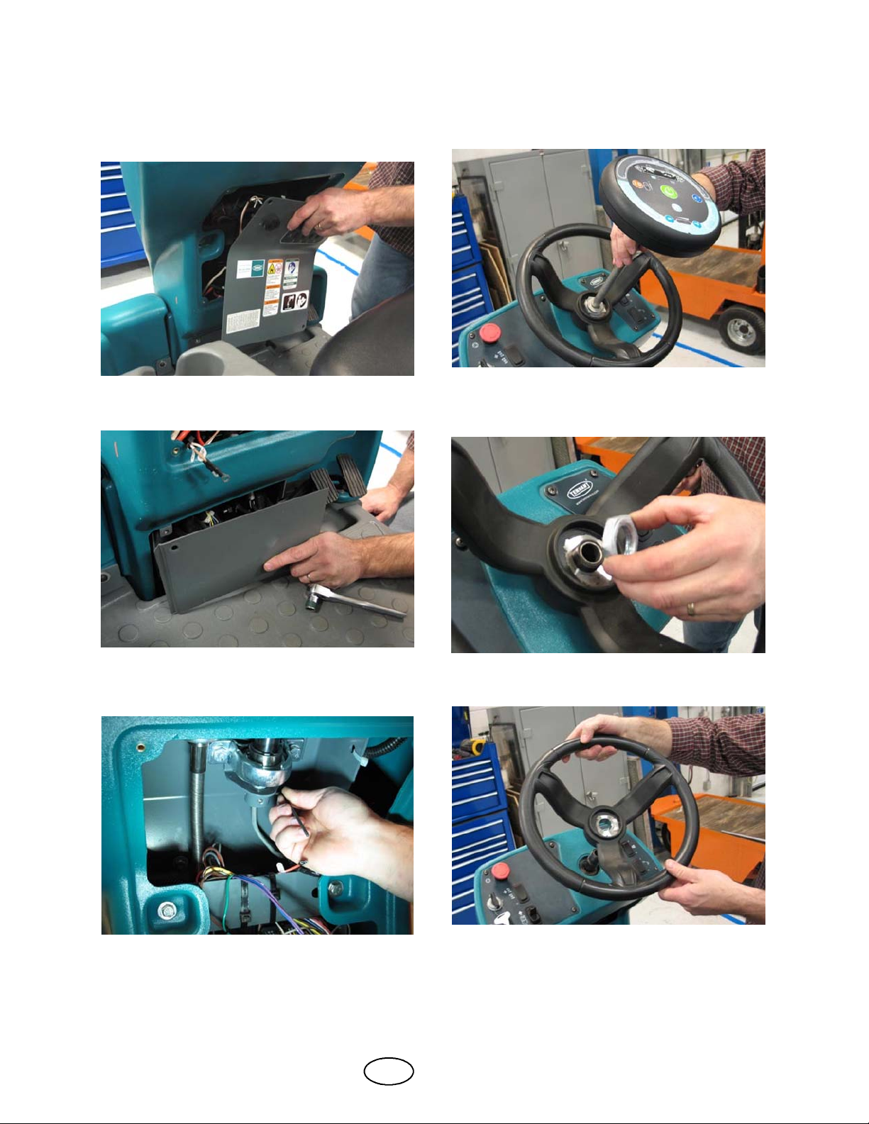
This kit contains the parts needed to replace the steering shaft on T16 scrubbers.
Please follow step-by-step instructions.
SPECIAL TOOLS / CONSIDERATIONS: 1--11/16 socket
(Estimated time to complete: 3 hours)
PROTECT THE ENVIRONMENT
Please dispose of packaging materials, old machine components, and
hazardous fluids in an environmentally safe manner according to local
waste disposal regulations.
Always remember to recycle.
PREPARATION:
FOR SAFETY: Before leaving or servicing
machine, stop on level surface, turn off
machine, and remove key.
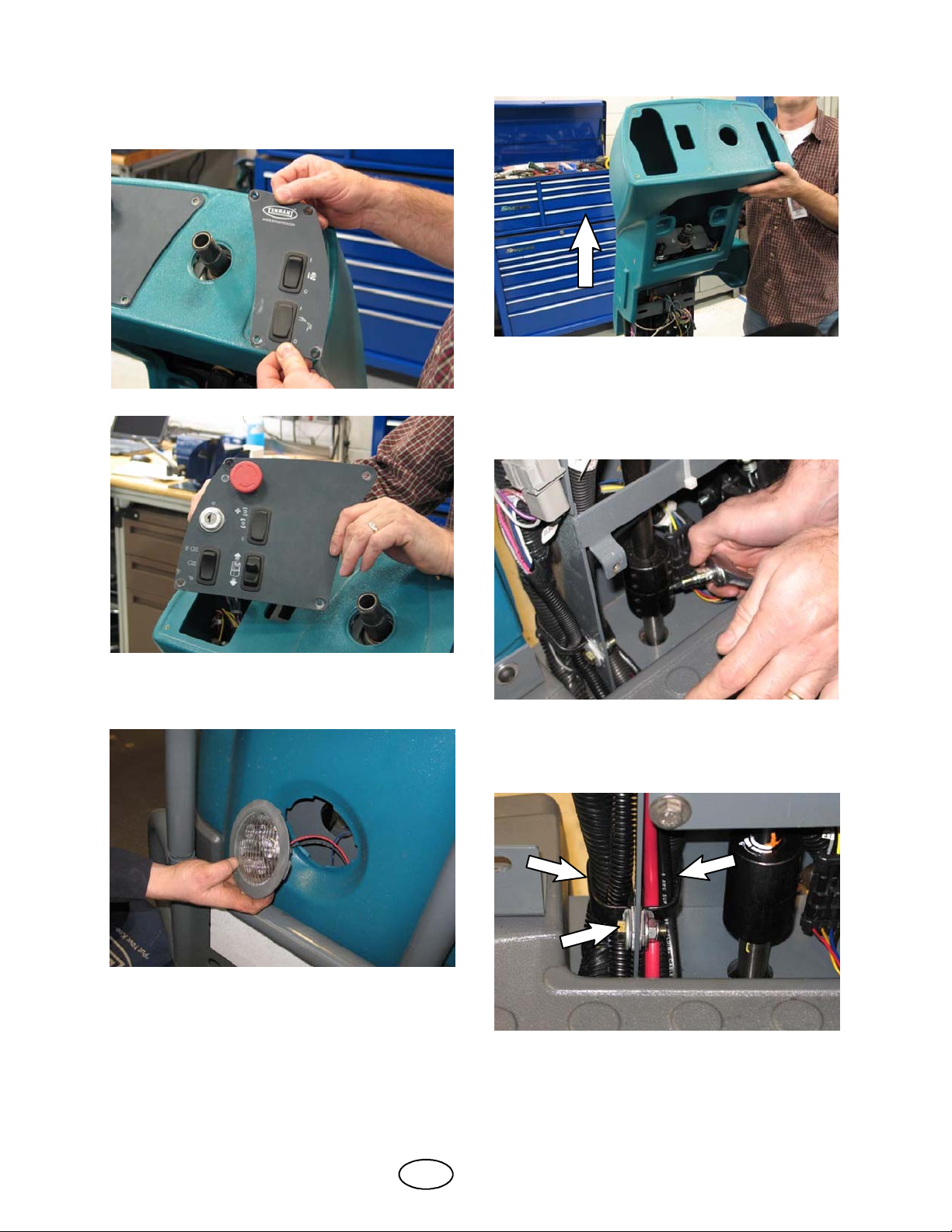
WARNING: Always disconnect battery
cables from machine before working on
electrical components.
NOTE:Do Not discard removed parts unless
instructed to do so. Set removed parts aside.
Most of these parts are reinstalled onto the
machine.
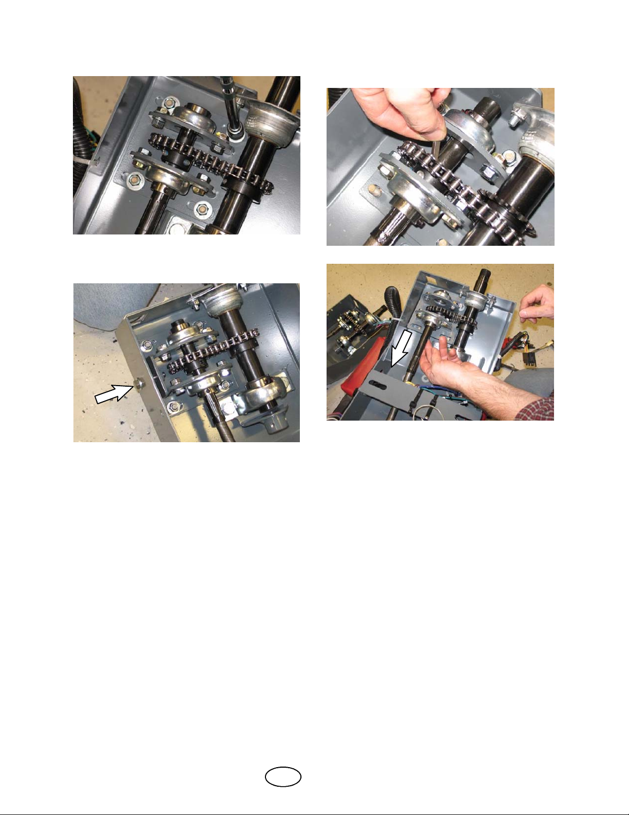
NOTE:Refer Fig. 54, Fig. 55, and Fig. 56 for
exploded views / part locations on the machine.
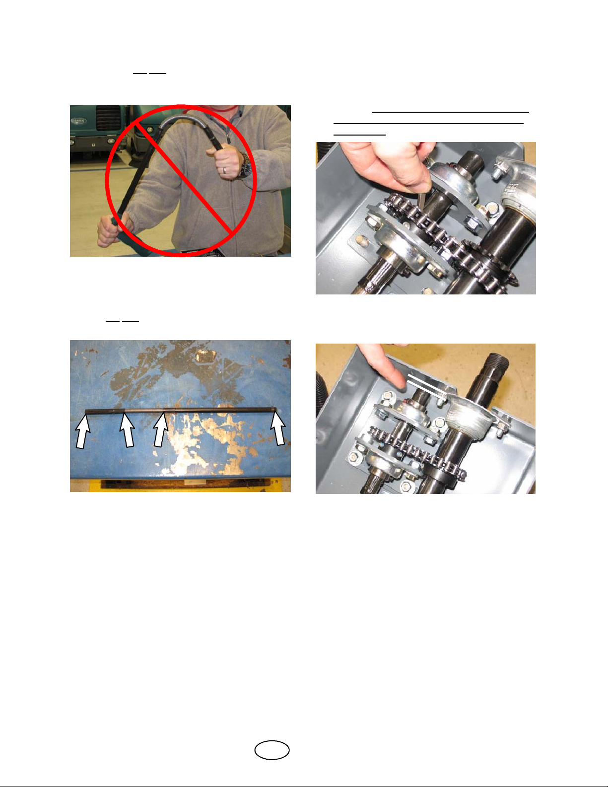
ATTENTION: Do Not bend the steering shaft
except for the slight bend necessary to install
it onto the machine.