Tenney BTS User manual

)
i
PAGE 2
Q
800
574
2748
323
770
0634
:
Please Note: This Manual is for reference purposes only and not Specific to this
Chamber. Each Chamber may vary depending on Age, Options, Controller, and
Individual Configuration

r· )
)
PAGE 3

TENNEY ENVIRONMENTAL
SAFETY
WARNINGS
.-
I
1.
PLEASE READTHE ENTIRE TENNEY INSTRUCTIONMANUALAS WELL AS THE
VENDOR MANUALS AND CUT-SHEETS PROVIDED, BEFORE OPERATINGTHlS
CHAMBER1 FAILURETOADHERE TO THE SAFETYWARNINGS, OR TO FOLLOW
THE PROPER OPERATING PROCEDURESLISTED THROUGHOUT THE MANUALS
AND INFORMATION PROVIDED, COULD CAUSEDAMAGE TO YOUR EQUIPMENT,
PERSONALINJURY, OR DEATH.
2.
A MAINPOWER DISCONNECTIS NOT PROVIDEDWlTH YOUR CHAMBER. ITIS
HIGHLY SUGGESTED THAT A DISCONNECTSWITCH ONA SEPARATEBRANCH
CIRCUIT BEINSTALLEDAS THE POWER SOURCE TOYOUR CHAMBER, IN
ACCORDANCE WlTH ALL NATIONALAND LOCAL ELECTRICAL CODES. IFYOUR
CHAMBER IS EQUIPPEDWlTH A POWER CORD AND PLUG, YOU MUST UTILIZEA
RECEPTACLEWlTH THE APPROPRIATE RATINGWHICH ISON A BRANCHCIRCUIT
OF ITSOWN. OPENING THE BRANCHCIRCUIT BREAKER INTHE TEST CHAMBER
DOES
NOT REMOVEALL POWER FROMTHE CHAMBER.
3.
ELECTRICALENCLOSURES, GAUGE BOXES, CONDITIONINGCOMPARTMENT,
etc.,
CONTAIN EXPOSED ELECTRICAL CONNECTIONS. DISCONNECTALL ELECTRICAL
POWER FROM THE FACILITYAT ITS SOURCE BEFORE SERVICINGOR CLEANING.
4.
DO NOTATTEMPT ANY SERVICE OR ADJUSTMENT TO ANY ELECTRICALOR
,---
MECHANICALCOMPONENTS DURING OPERATION.
)
5.
KEEP PANELS INPLACEPROPERLYWHEN THE CHAMBER IS INOPERATION.
6.
THlS ISNOTAN EXPLOSIONPROOFCHAMBER
-
THEAIR CONDITIONINGSECTION
CONTAINS LOW MASS, OPENWIRE HEATINGELEMENTS. DUE TO THlS LOW MASS,
THE HEATERELEMENTSCANREADILY ATTAIN TEMPERATURES SUFFICIENTLY
HlGHTO IGNITEGAS VAPORS. DO NOT INSTALLTESTARTICLES THAT MAY
RELEASE EXPLOSIVEOR FLAMMABLEVAPORS INTHE CHAMBER.
7. REFRIGERANTS UNDER HlGHPRESSUREARE USED. SERVICEOF THE
REFRIGERATIONSYSTEM MUST ONLY BECARRIEDOUT BYA QUALIFIED
REFRIGERATIONMECHANIC.
8.
HUMANEXPOSURETO TEMPERATURE EXTREMES CANCAUSE INJURY. TAKE
APPROPRIATE PRECAUTIONS BEFORE OPENINGCHAMBER DOORSAND UPON
HANDLING TEST SPECIMENS.

TENNEY ENVIRONMENTAL
INSTALLATIONINSTRUCTIONS
READ THE FOLLOWINGCOMPLETELYBEFOREATTEMPTINGTO INSTALLOR
OPERATE THE EQUIPMENT.
IMPORTANT!
--
FOR ALL MODELS EXCEPTBTS. BTC. T6S. T6C
CAUTION: TO SAFELY SECURETHE REFRIGERATIONSYSTEM COMPRESSORS AND
PIPING DURING SHIPPING, WOODEN BLOCKS HAVE BEENINSTALLEDUNDERNEATH
THE COMPRESSORS. THESE BLOCKS MUST
BE
REMOVEDBEFORE OPERATION!
SERIOUSDAMAGEMAY RESULT IFNOT REMOVED1
ON COMPRESSORS WlTH SPRiNG$lOaNTS ONLY, YOU MUSTLOOSENTHE
COMPRESSOR HOLD DOWN NUTS JUST ENOUGHTO REMOVE THE BLOCKS. DO NOT
LOOSENNUT BEYOND TOP OF BOLT.
ON COMPRESSORSWlTH
RUBEER~OUNTS
ONLY, JUST SIMPLY SLIDETHE WOODEN
BLOCK OUT. DO NOT LOOSENANY NUTS.
DELIVERY: Inspectequipment and shipping crate immediatelyuponreceipt. If any damage is
apparent, please contact the transportationcompany immediately. Retain all shippingmaterials
for inspection. Any claims for damage muststart at the receivingpoint. Check packingslip
carefully and make sure allmaterials have been receivedas indicatedon the packingticket.
Unless othewise noted, YOUR ORDER HAS BEENSHIPPED COMPLETE.
CAUTION!
Benchtopandreach-inchambers shouldbe handledand transported inan
upright position. Itmustnot becarriedon its back, front, orany side.
lmpo?tanfi Doto the vibration incurredduring shipping and handling, it is possiblethat
mechanicalconnections such as water fittings may become loose. For chambers with a water
cooled refrigerationsystem, check all water fittings to make sure they are t~ght.
GENERAL INFORMATION: Your equipment has beenfully operated, tested. and balancedin
our plant priorto shipment.Make sure the chamber is leveledwhenset up. Many times control
panels are removed to facilitate shipment. Replacementusually involves repositioningpanels
on the equipment mechanicallyand reconnectionOf numberedwires to matchingnumbered
terminalblocks. The chamber should be installedin an area where there is goodair ventilation,
especially if anair-cooledcondenser isused. Allow a minimumof
12
inches between any wall
and chamber side.
AIR SUPPLY CONNECTION(S): Your chamber may haveone or more air supply connections
which may includecompressed air, purged air, or other. Please check your chamber
specifications for completedetails. Make sure all air supplies are clean and that all connections
are secure.
GN,
I
LN,
I
CO, CONNECTION(S): Your chambermay requirea supply of GN,, LN,, or CO,.
Please check your chamberspecificationsfor completedetails. Makesure all connections are
secure.
TENNEY ENVIRONMENTAL
WATER SUPPLY CONNECTION(S): Ifthe chamber utilizes a water-cooled refrigeration
/-.
!
condenser,connect the supply to the Water-In connectionat the rear of the chamber. Connect
the Water-Out connectionto
an
opendrain.
POWER CONNECTION: WARNING1
--
BEFORE MAKING
THE
POWER SUPPLY
CONNECTION TO YOUR CHAMBER YOU MUST DO THE FOLLOWING:
1.
Verify the power supplyvoltage rating establishedfor yourchamber. The voltage
rating isfound onthe serial tag onthe side of the chamber.
Pleasenotethe ratedvalue here:
2.
Measureand recordthevoltage source you intendtosupply your chamberwith.
Pleasenotethe measuredvalue here:
3. Go to the section entitled "Line Voltage" inthis manual. Verify that the power supply
voltage source you measured and recordedis withintheminimum and maximum
allowable operating voltages for your chamber rating. Ifit is notwithin this operating
range, do notmake the power connectionl Otherwise, erratic operation and damage
may occurto your chamber which may void your warranty. Callthe Tenney Service
Departmentwith any questions.
A
main power disconnect is not providedwith your chamber. Itis highlysuggested that a
disconnect switch on a separate branchcircuit be installed as the powersource to your
chamber, in accordance with all nationaland local electricalcodes. Make sure equipmentis
.-
properly grounded in accordance with all codes. Forunits providedwith a cord andplug,
)
simply connect to a receptaclewhich hasthe appropriatepower supply on a branchcircuit of
itsown. Otherwise,connect incomingpower supply to the main inputconnectionsprovided.
Most units have a main line block connectionwhich is labeled for the correct service.
Unitswith three phase motors must becheckedto insureproper motor rotation.
A
redarrow is
locatedonthe motorhousing to show properrotation. If it is opposite,simply reverse two of the
linefeeds to obtainproperoperation. Failureto check motorrotationmay result in DAMAGE
TO THE EQUIPMENTdue to opposite airflowor no airflow. If the equipment hasmore than
one motor,they haveall beenproperly phased at the factory.
Beforeenergizingany equipment give ita visual inspectionfor loosecomponents,
electrical connections, fittings, etc. Shutall operating switchestothe "off" position
beforeenergizing.
Pleasehavetrained personnelstart and check out theequipment before itsfirst cycle.
TENNEY ENVIRONMENTAL
-
LINE VOLTAGE
I
One of the most common causes of chamber malfunctionis low linevoltage as the power
source to the chamber.Ordinarily inthis condition, the compressormotorswouldoperate
erratically, eventually overheat and shut down. You must becertainthat your equipment is
connectedto a circuit with an adequate voltage and currentsource. An oversupplyvoltage
would also cause erratic operationand eventualshutdown or damage to your equipment.
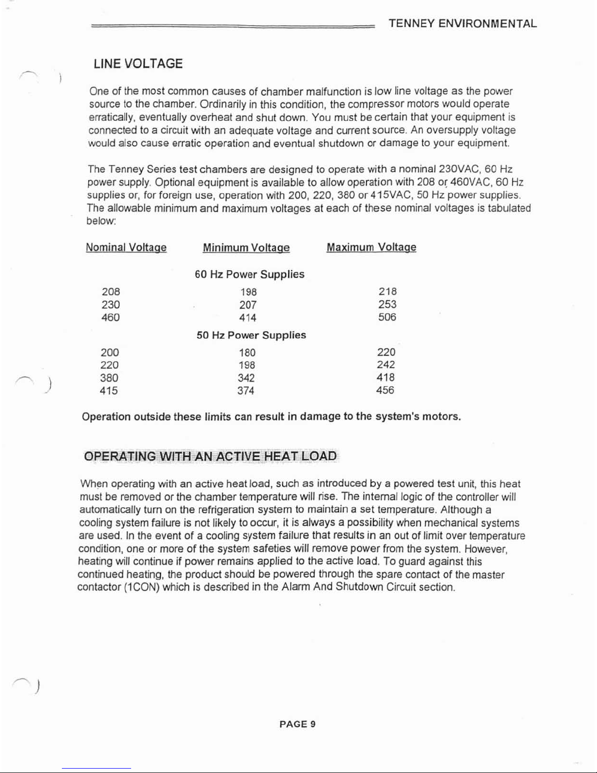
The Tenney Series test chambers are designedto operate with a nominal230VAC, 60
Hz
power supply. Optionalequipment is availableto allow operationwith208 or460VAC, 60
Hz
supplies or, for foreign use, operation with 200, 220, 380 or415VAC. 50
Hz
powersupplies.
The allowable minimum and maximumvoltages at eachof these nominalvoltages is tabulated
below:
NominalVoltaae Minimum Voltaae MaximumVoltaae
60
Hz
Power Supplies
198 218
207 253
414 506
50
Hz
Power Supplies
180 220
198 242
342
418
374 456
Operation outsidethese limits can result
in
damage tothe system's motors.
OPERATINGWITH-AN
ACTIVE
HEAT LOAD
When operatingwith an active heatload, such as introducedby a powered test unit, this heat
must be removedor the chambertemperaturewill rise. The internallogic of the controllerwill
automaticallyturn on the refrigerationsystemto maintaina set temperature.Althougha
cooling systemfailure is not likelyto occur, it is always a possibilitywhen mechanicalsystems
are used. Inthe event of a coolingsystem failure that results
in
an out of limit over temperature
condition, one or moreof the system safeties will removepower from the system. However,
heating
will
continue if power remains appliedto the active load. To guardagainst this
continuedheating, the productshould bepoweredthrough the spare contact of the master
contactor (ICON)which is describedinthe Alarm And ShutdownCircuit section.
PAGE
9
TENNEY ENVIRONMENTAL
-
TEMPERATURE CONTROL
-
WATLOW
942
CONTROLLER
1
Temperature conditions are attainedand controlledby a Watlow 942 microprocessorbased
controller. Temperaturemeasurementsare made utilizing a 100ohm platinumRTD sensor.
This controllerfeatures dual outputs, auto-tuningcontrolwith 24 step programcapability and
easy fixed set point operation.
Heatingof the chamberisaccomplishedwith the time proportioned(PID) Output ICI-01 of the
controller, which turns on a triac inthe heater circuit supplying powerto the heaterelements.
Coolingof the chamberis accomplishedwith ONIOFF Output ICI-02of the controller,which
energizes a contactorsupplying powerto the refrigerationcircuitry.
IMPORTANTI
Output 1CI-02isset up for ONIOFF controlandthe PIDvalue is set to zero
Do not change the PIDvalue for channeltwo under any circumstance!
--
Corn~ressorTurn-On
Loaic
Indeterminingwhen to turn the refrigerationsystem on or off, the controller'slogicwill compare
the following signals and setpoints.
1.
Actual Chamber Temperature
2.
SetpointTemperature
3.
Hysteresis
4.
Deadband
-
)
Hysteresis
(HYS)
anddeadband
(db)
are parameters entered at thefactory. Hysteresisis the
temperaturechange necessaryto changethe output from full ON to full
OFF
andis detailedin
the Setup Menusection inthe Watlow 942 Manual. Deadband is the span inwhich Output ICI-
02will remainON belowthe controller's low setpoint, and isdetailed inthe Operation Menu
sectionof the Watlow Manual.
HYSand
db
are entered
in
degrees
C.
Deadbandis always enteredas a
(-)
minus.The logic is
as follows:
Measuredtemperature rises above setpoint: Refrigerationturn-on equals
hysteresisminusdeadband.
Measuredtemperature falls below setpoint: Turn-on is always above setpoint.
Tum-off is always below setpoint: Turn-on is always above setpoint.
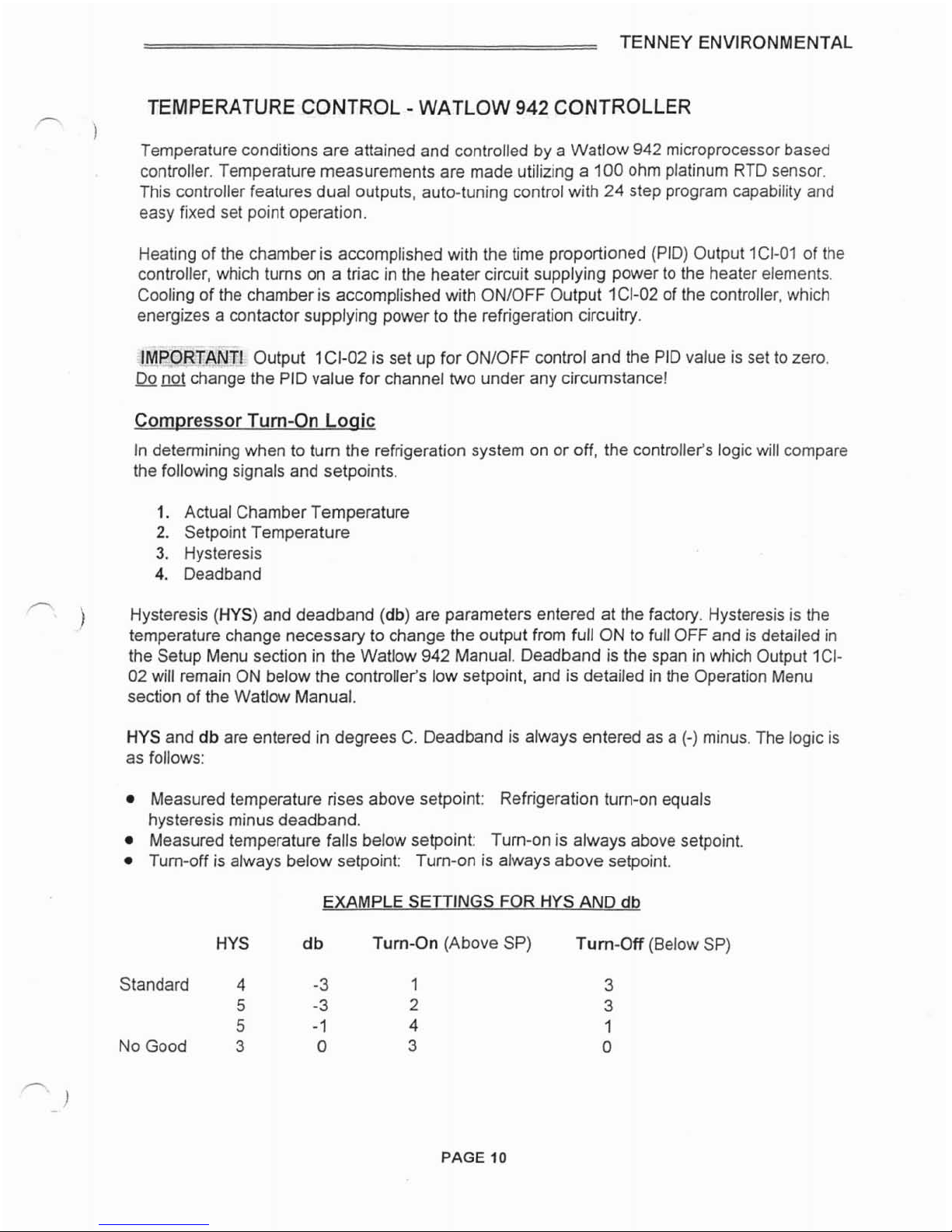
EXAMPLE
SETTINGS FOR HYSAND
db
HYS
db
Turn-On (AboveSP) Turn-OR (Below SP)
Standard 4
-3
1
5
-3
2
5
-
1
4
NoGood
3 0
3

TENNEY ENVIRONMENTAL
r--
Chambers are shipped with
HYS
=
4,
and db
=
-
3,
as shown onthe top line in the above
examples. It
is
unlikely a changeto these settings will be required. Fortunately, these settings
are not subject to "coldstart" default, andwill remainvalid afler a power interruption.They are
held in EEROM, not battery-backed RAM.
The pre-programmedconfigurationof the Watlow
942
is
documentedin the Test Report.
Pleaserefer to this and the Watlow 942 user's manual for completeoperationaldetails. These
are found in the SupplementalInstructionsSection.
Controller Versions
The Watlow 942 Controlleris provided infour versions with the following nomenclature:
1.
The basic 24-step rampingcontrol: 942A-3KDO-AE00
2.
Basic plus two events: 942A-3KD2-AE00
3.
Basic plus communications: 942A-3KDO-BE00
4.
Basic plus events andcommunications: 942A-3KD2-BE00
The nomenclatureis printedonthe back of the controllerand can be seen when the chamber's
controlpanel
is
opened.
NOTE: The communicationsarrangementis isolated RS232lRS423, RS422, EIA-485, or IEEE.
Each event output is through a mechanicalrelay having contacts rated
6
Amps,
120
or
240
VAC.

TENNEY ENVIRONMENTAL
-
ALARM AND SHUTDOWN CIRCUIT
1
A
comprehensive alarm and shutdowncircuit may be provided for multiple protectionagainst
product overtundertemperature and chamber over temperature. The sensor utilized for
temperature measurementand the Heat Limiter Fuse are normallyplaced at the plenum in the
downstream airflow. This is the most responsivearea of the chamber.
Chamber Over Temperature Protection: The following device is used,
1.
HeatLimiter (HL)
-
-
TemperatureActuated Fuse (Standard)
Product OverIUnderTemperature Protection: The following optional device may be used.
With this option, a
100
ohm platinum RTD
IS
utilizedfor temperature measurement.
1.
Watlow
93
Controller
-
-
TempGard IV Feature
-
HighlLowLimits (Optional)
WARNING! When Master Contactor ICONis deenergized duetoANY alarm condition
described below, power is only
removed
from the conditioning control circuitry. The
instrumentationandalarm circuitry will still be energizedl
For any questions concerningtheoperationof any of the controllers described below, please
reference the appropriate user manual locatedinthe SupplementalInstructionsSection.
CIRCUITOPERATIONS<
'
~)
NormalConditions:
When chambertemperatureiswithin the selectedsetpoints the switch (green) ON light is
illuminatedandthe Master Contactor ICONisenergized. The contacts of ICONprovide
powerto the conditioning control circuitry. (Withthe optionalalarnlbuzzer1silence switch or
TempGard IV feature, the NORMALlight 2LT will illuminate. When either of these optional
features are used, the main controlswitch will not be equipped with any integrallights.)
Note:
A
spare set of ICONcontactsare providedfor the customer'sclosure. It is
recommendedthat these contacts, wired to terminal blocks
#14
&
#15,
be usedto energize an
active heat load if utilized.
Ovened HeatLimiter:
When a predeterminedhightemperature limit isreachedandthe Heat Limiter Fuse (which
looks likea regularfuse) opens. Master Contactor ICONwill deeneraize alona with the
conditioningcontrol circhitj. The switch OVERTEMP lightwill illuminateand the switch ON
lightwill extinguish. (Withthe optional alarm buzzer
I
silence switch feature, boththe red
chamber
OVERTEMP
light
~LT
and redALARM light
4LT
will immediately illuminate, bealarm
buzzerwill sound, and the NORMALlightwill extinguish.)When the Heat Limiter Fuse opens,
it bereplaced.
WARNINGI
Whenreplacing the Heat Limiter Fuse, make sure all power
IS
completely
disconnectedfrom the chamber. Open the closest main power disconnect and pull the plug (if
,-
1
provided) from the outlet.

TENNEY ENVIRONMENTAL
-
TempGard IVAlarm
-
-
O~tional:
1
When a presettemperature limit isreachedwithin the Watlow 93 TempGard IV, the TGlV
alarm contacts open to deenergizeMaster Contactor ICON,which removes powerfrom the
conditioningcontrolcircuitry. The NORMAL light is nowextinguished,the redALARM light
4LT
illuminates, and the alarm buzzer sounds. The red Chamber OVERTEMPlight 3LTwill
illuminatewhen the alarm conditionclears
and
the TernpGard IValarm is clearedas detailedin
the Watlow 93 manual.
Note: The alarm buzzerwith silence switch is an optional feature for all chambers. This alarm
circuitry comes standardwith the Watlow 93 TempGardIVfeature. The TempGard IV
configurationis shown inthe "Watlow 93 TempGard IVConfigurationAnd Use" section.
Svstem Reset For
Alann
Buuer
I
Silence SwitchorTemoGardIVOption
-
-
Important!
After an out of limit condition hasbeen corrected, the conditioningcontrolcircuits must be
restarted by momentarily pressingthe RESET button IPB. You must rememberto clear the
Watlow
93
alarm message.
A
1.5
second timer ITC,is included
in
the reset circuit to providefor automatic start when
power is applied to the chamber. This avoidsthe needto press the resetbutton each time that
power is removedand reapplied.
Alarm Buuer
&
Silence Switch
- -
O~tional:
With this option the silenceswitch disables the alarm buzzerwhile correctiveaction is taken.
,-
When 1SSis activated, the white Silence light
5LT
will be illuminated. If the alarm buzzerwas
)
disabled and the system was successfullyreset with IPB,the alarm buzzer will now sound to
alert the operator to place the silence switch 1SS
in
it's normal (down) position.
Heatingof the chamber is accomplishedwith the time proportionedoutput 1CI-01of the
Watlow
942
Controller,which turns ontriac ITRCto supply powerto the heaterelements.
These elements are open air lowmass nichrome wires, which havelow thermal lag and
provide rapidresponseto the controller's demands.The heater elements are isolatedfrom the
workspace to preventdirect radiationto the product. Please referencethe electrical schematic
for your particularchamber's heaterbank ratings.

TENNEY ENVIRONMENTAL
SINGLE STAGE REFRIGERATION SYSTEM DESCRIPTION
-.
1
The basic single stagesystemconsists of a compressor, anoil separator (exceptfor Models
BTS,T6S,
T27,
&
T65), either an air cooledorwater cooled condenser, an evaporatorcoil
(locatedinthe chamber conditioningsection)which is providedwith a capillary (tube)type
expansion device, anda suctionlineaccumulatorto guard againstliquidrefrigerantreturnto
the compressor.
Refrigerantflow is fromthe compressoras a hot compressed gas throughthe oil separatorto
the condenser. Here the refrigerantcools andcondenses to liquidform and flows through the
capillary tube to the evaporatorcooling coil inthe chamber conditioningsection. Warm
chamber air is circulated throughthe coolingcoil andheat exchange occurs as the liquid
refrigerantboils, vaporizes, and absorbs heat. The vaporized refrigerant returnsto the
compressorthrough the suction lineaccumulator
SLA.
The cycle
is
repeated.
Forall unitsexcept Model
BTS,
a
thermostat is mountedonthe suction returnline near the
compressorto monitorthe temperature of the retumgas flow. When a predeterminedhigh
temperature is reached,the thermostat will energize an artificialloadingsolenoid, which will
injectrefrigerantthrough a capillarytube into the suction side ofthe system. This action will
maintain a positivecoolrefrigerantflow to the compressor, preventingoverheatingof the
compressor and the dischargegas.
,-.
The basic cascade system consists of a low stage compressor, a high stage compressor, an
'8
)
evaporatorcoil, anda cascade condenser.
The low stage system includes an oil separator(for models with compressor motors greater
than
IH.P.),
a cascadecondenser,an expansion tank, and an evaporator coil (locatedinthe
chamber conditioningsection) which is providedwith a capillary (tube) type expansion device
The high stage system includes an air cooledorwater cooled condenser, a capillarytube
which feeds the cascade condenser, and
a
suction line accumulatorto guard against liquid
refrigerantretum to the compressor.
The functionof the cascade condenserisfor the highstage refrigerantto cooland condense
the low stage refrigerant. This permits greaterSystem efficiency and allows lower chamber
temperatures to be reachedthan what can beattainedwith a single stage system. The low
stage liquidrefrigerantfrom the cascade condenser is metered through
a
capillarytube to the
evaporatorcoil. Heat exchangetakes place hereas the liquidrefrigerant convertsto a gas and
then returnsto the lowstage compressor.
A
thennostat is mountedon the suction returnlinenearthe low stage compressor to monitor
the temperatureof the return gas flow. When a predetermined hightemperature is reached,
the thermostatwill energizethe Artificial Loading solenoid 14SOL,whichwill inject refrigerant
intothe suction side of the system.
It
will first enter the expansiontank where the added
volume permitsthe charging of additional refrigerantwithout increasingthe standby or
charging pressurebeyondworkable limits. Refrigerantgas is then sucked out of the expansion
,-
tank and meteredthrough
a
capillarytube to the suction side of the low stage compressor.
.
~
)
This actionwill maintain a positive cool refrigerant flow to the compressor, preventkg

TENNEY ENVIRONMENTAL
overheatingof the compressor and the discharge gas.
-
)
A high pressurecut-in sensor monitors the pressureinsidethe lowstage compressor
and will activate the Load Limit Switch 4PS when the low stage discharge pressurereaches
280 PSIG. This will energizethe Artificial Loading solenoid 14SOLwhich will inject refrigerant
intothe suction side of the systemas describedabove. Switch 4PS preventsthe compressor
from cycling on and off in responseto signals from the high pressurecut-out switch. 4PS will
openwhen pressurefalls to 240 PSIG.
Formore detailedinformationon acascadesystem, please referencethe section entitled
"Servicing Cascade RefrigerationSystems".
REFRIGERAT~N
SYSTEM
SAFETY
DEVICES
The refrigeration system is providedwith several safety devices that stop the compressor(s)
from ~nningif conditions exceed preset limits. In a cascade systemboth the low stage and the
highstage includethese safety devices. With a low limit conditionthe
HI-LO
PressureCutout
Switch 1PS (and 2PS for cascade)will continueto automaticallyreset untilsufficientpressure
develops. With a highlimit conditionyou must manuallv reset IPS(or2PS). If the compressor
continues to trip off have the system checked by
a
qualifiedrefrigerationsystem mechanic.
The possiblecauses of a highor low limitcutout are as follows: NOTE:
The
HI-LO Pressure
Cutout Switch does not apply to the Models BTS. BTC.T6S, andT6C.
HighPressure Cutout
(1
PS, 2PS)
-
-
Opens if a preset compressor dischargepressure
'-
.)
is exceeded. Probable cause for high stage cut-out is insufficientcoolingwater (water
cooledsystems) or restrictedair flow (air cooledsystems). Probable cause for low stage
cutout is a malfunction of the high stage system. IPSRPS are typically set at
300
PSIG.
Low PressureCutout
(1
PS, 2PS)
-
-
Opens if the compressorsuction pressurefalls
below a presetvalue. Probablecauses are a loss of refrigerant(eitherstage) or restricted
air flow across the evaporator (low stage).
1
PSl2PSare typically set at
6
inchesof vacuum.
MotorOverload
-
-
Opens ifthe motorwindings exceed a preset temperature. Probable
causes are insufficientflow across the motor dueto a refrigerantlossor a failure of the
liquidinjectionvalve providedfor suction gas cooling. The motoroverloadis installed
directly in the motorwindings and will automaticallyreset andrestart the compressorafter
the motorhas cooled.
TENNEY ENVIRONMENTAL
WATLOW
93
-
TEMPGARD
IV
CONFIGURATION
&
USE
(Optional)
-
I
As an option, your chamber may include the TempGard IV feature with the Watlow
93
Controller. The circuitoperation description is explained inthe AlarmAnd Shutdown Circuit
section of this manual. This configuration section serves as a briefreferenceguide. For
completedetails ofthe Watlow
93
Controller, please reference the user manual.
When properly configured, the lower display of the control will be blank and the upper display
will show the actual temperature as measured by the control's RTDsensor, when conditions
arewithin the alarm settings. If an out of limitcondition occurs, the lower displaywill flash "HI"
or
"LO"
depending on the particular fault.
IMPORTANT: ForAll Models
-
When the alarm has cleared you must press the
RESET pushbutton
1
PB.
To configure the controlto perform as described above, power it upand select the setup menu
by pressingthe UPIDownarrow keys simultaneously. Pressing the
"M"
key then allows you to
scrollthrough the set up parameters.
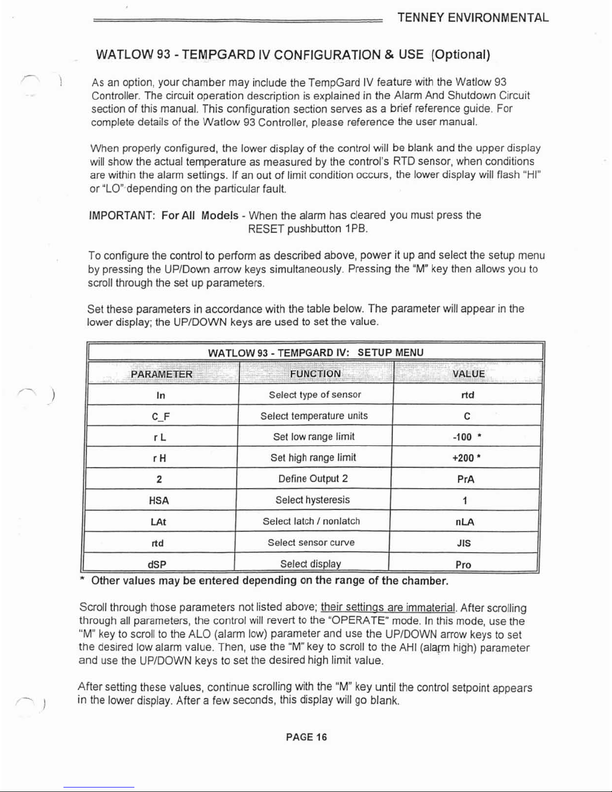
Set these parametersin accordance with the table below. The parameterwill appear inthe
lower display; the UPIDOWN keys are usedto set the value.
WATLOW
93
-
TEMPGARD IV: ENU
-.--.-I
PARAMETER
,
-
In
11
r
H
1
Set high range limit
1
+200
11
c-F
r
L
11
2
1
DefineOutput
2
I
PrA
11
FUNCTION
II
Select
type
of
sensor
11
HSA
I
Select hysteresis
1
1
11
VALUE
ltd
Selecttemperature units
Set low range limit
C
-100
'
dSP
I
Select display
I
Pro
Other values
may
beentereddepending on the range of thechamber.
LAt
ltd
Scrollthrough those parameters not listedabove; their settinos are immaterial.After scrolling
through all parameters,the controlwill revert to the "OPERATE" mode. Inthis mode, use the
"M"
keyto scroll to theALO (alarm low) parameter and use the UPIDOWNarrow keys to set
the desired low alarm value. Then, use the
"Mu
key to scroll to the AH1 (alamhigh) parameter
and usethe UPIDOWNkeys to set the desired high limit value.
After setting these values, continue scrolling with the
"M"
keyuntilthe controlsetpoint appears
-
1
inthe lower display. After a few seconds, this displaywill go blank.
Select latch
I
nonlatch
Select sensor curve
--
nLA
JIS
TENNEY ENVIRONMENTAL
BOOST HEAT (Optional)
-
)
As an option, your chambermaybe equippedwith the boost heat feature which includes extra
heaters to provide rapidincreasesin temperature. The boost heat will automaticallytum on ifa
preset time delay relaytimes out, indicatingthat the desired temperature has not been
achieved.
As output 1CI-01of the controllerenergizes the main heater bank, ICI-01will at the same time
energizea time delay relay.When this relay times out it
will
energize a mercury relay, which
providespower to the boost heaters.A mechanicalcontactor is also providedwhich has it's
contactswired intothe power supply line to the boost heaters. This contactor is providedto
deenergizethe heaters in the event of an over temperature condition.
BOOSTCOOLING (Optional)
USING LIQUIDNITROGEN or
CARBON
DIOXIDE
As an option, your chambermaybe equipped with a boost cooling system which is activated
byan event output from the Watlow 942 Controller. Cooling is achievedby injectingeither LN,
or
CO,,
depending on the optionpurchased, into the chamberthrough a solenoid valve. To
activate the system the event must beturned on as explained inthe Watlow
942
Controller
manual.
Event No.
1
is generally used for this function. However,a referencetable definingthe function
of each event is affixed to the controlpanelof each chamber. Please check this table before
1
operatingthe chamber.
Once enabledthrough the event, the cooling will turn on if a demand for coolingexists for a
presettime period.
A
timer connectedto the time proportioned output of the controller"times
our' and energizes the cooling solenoid valve if the output is 100percent "ON"indicatinga
needfor additional cooling.
When the desiredtemperatureis attained andthe controllerheat output begins to turn on, the
boostcoolingfunctionwill cease.
LN, systems are providedwith a manuallyset flow adjustingvalve providedto allow for
adjusting the flowto avoid incompleteevaporationat valying
LN,
supply pressures.A setting
of
4
tums open generally provides good perfomlance at asupplypressure of 20 to
25
PSIG.
This valve may be readjusted as necessaryto accommodatethe supply pressureat the end
use point.
TENNEY ENVIRONMENTAL
PURGEAIR SYSTEM
(Optional)
-
USING COMPRESSED AIR
or
NITROGEN
i
As an option, your chamber may be equippedwith a dry air or GN, purge system which is
activatedby an event output from the Watlow
942
Controller. To use the system, the event
must be turned on as explained in the Watlow
942
manual. EventNo.
2
is generally used for
this function.However,a referencetable defining the function of each event is affixed to the
controlpanelof each chamber. Please check this table before operatingthe chamber.
A
metering valve and flowmeter is supplied as part of thesystem to establishthe design purge
flow. The valve should
be
adjusteduntilthe indicatedflow isabout 300 cubic feet per hour.
The
GN,
purge system is primarilyutilizedto provideaninert atmospherewhich minimizes the
buildupof moistureand preventscondensationonthe product undertest. Eliminatingthe
oxygeninthe chamber air helps prevent corrosion of the product under test.
A drier is providedfor compressedair purgesystems. This system requires
a
supply of
relativelyoil free compressed air at a minimum pressure of 80 PSIG. This air is dried by a twin
tower heatless, self regeneratingdryer and is introduced intothe chamber through
a
solenoid
valve.
As anoption, your chamber may be providedwith either a circularor strip type chart recorder
'
)
to recordtemperature versus time. This recorder istypically a one pen type which also digitally
displays the processvalue.
A
100ohm platinum RTD is used for temperature measurement
and is normallyplacedin the plenum of the chamber.
The recorderconfigurationis documentedinthe Test Report, which is locatedinthe
Supplemental Instructions Section. For complete details on the operation of the recorder,
pleasereferencethe recorder's user's manualwhich is locatedin the same section.
PAGE
18
TENNEY ENVIRONMENTAL
DATA
COMMUNICATIONS (Optional)
7
1
As an option, your chamber may includedata communications withthe maincontrolletsserial
port. When employed, either a Data Communications manual or a Computer Interfacemanual
will be includedinthe Supplementallnstmctions Section.As a reference,the availabledata
types are listedand briefly described below. Please contact
a
Tenney Sales Engineerfor more
informalion.
RS232C
I
RS423A: Both interfaces are compatibleand use
3
wires: a singletransmitwire;
a
single receivewire; and
a
commonline. The maximum wire length
is
50 feet. Only a single
chambermay be connected to your computer. Data signals are measured as plus and minus
12volts to commonwith RS232C, and plus and minus 5v71ts to common with RS423A.
RS422A: This interfaceuses
5
wires: a transmit pair; a receivepair;anda common line. Up
to ten chambersmay be connected to your computer on a multi-drop network up to 4,000 feet
long. Data signals in each pair are measuredas a plus or minus5 volt differential.
EIA-485: This interface usesonly
2
wires. Both wires are usedfor transmittingandreceiving
data, and therefore, only one device may talk at a time. Up to
10
chambers may beconnected
to your computer on a multi-dropnetwork up to 4,000 feet long. Data signals are measured as
a plus or minus
5
volt differential.An EIA-485 card must be installedfor signalconversion.
IEEE-488: This is a parallel multi-dropinterface with several controland data lines. Each
device connected must be setto a uniqueaddress. Datafrom other test devices may also be
collected.Since the controllers we use only have serial communications, an IEEE-488to serial
'
)
converter card isinstalledinthe chamber. Maximumcable lengthisapproximately
33
feet for
all devices.

TENNEY ENVIRONMENTAL
LinkTenn
SOFTWARE
(Optional)
-
)
Welcome to anotherunique optionalfeature developedbyTenney Environmental.
LinkTenn software isdesignedto operate on a remotecomputer system and provide complete
control of Tenney Environmentaltest chambers.This is accomplished by communicating
through a RS232lRS422interfacewith the VersaTenn Ill or Watlow 942, 945, and 988
Controllers. Up to ten chambers may be controlledfrom one computerwith RS422 interface.
LinkTennsoftware isprovidedboth in a DOS format and in a Windows format on
3%
inch
diskettes. Inthe DOS format, "LinkTenn
II"
software is designedto work with the VersaTenn
Ill
Controller, and"LinkTenn942"software is designedto work with the Watlow 942 Controller. In
the Windows format. "LinkTenn For Windows" software is designedto work with the
VersaTenn
Ill
and the Watlow 942, 945, and988 Controllers.
The hardwareand software requirements to run LinkTennsoftware inbothformats are listed
below.
DOS
Format: LinkTenn
II
&
LinkTenn
942
1.
Any DOS basedcomputer
2.
256K
of
RAM
memory
3.
CGA graphics card
4.
DOS
2.0 or higher
5. RS232 computerinterfacefor single chamber control
6.
RS422 computerinterfacefor multiplechamber control
7.
With IEEE-488communications, a NationalInstruments PC2A or compatible card
1
Windows Format: LinkTennForWindows
1.
Computerwith 486 processor or higher
2. Eight Megof harddrive memory
3.
Eight Megof
RAM
memory
4. Windows
3.X
operatingsystem or higher
5. RS232 computerinterfacefor single chamber control
6.
RS422computerinterfacefor multiplechambercontrol
7.
Currently not availableto work with IEEE-488communications
A sample menudisplay screenentitled "ProgramControl"from the LinkTenn For Windows
program,
is
providedin the SupplementalInstructions Section. This screen shows some of the
uniquefeatures incorporatedintothe programalongwith sample setpoints.
When LinkTennsoftware is providedineitherformat, a correspondingLinkTennUser's Manual
will be providedinthe SupplementalInstructionsSection.

TENNEY ENVIRONMENTAL
CHAMBER OPERATION
/.
)
To operate the chamber, turnonthe power source to the chamber and close all chamber
circuit breakers.The display of the Watlow
942
should now be illuminated. Enterthe desired
temperature programor manualsetpoints as explainedin the Watlow
942
user'smanual.
Closethe Power On switch 1SS.The green ON light should be illuminated.
If your chamberincludesthe optional Watlow
93
Controllerwith TempGard IV feature, set this
controller's highnow temperaturelimits at this time. Referto the "AlarmAnd Shutdown Circuit"
descriptionand the "TempGard IV ConfigurationAnd Use Instructions"for further details.
Forthose chambers which includeany otheroptions, please referto the appropriate "optional"
manualsectionsfor
a
detailedoperationdescription.
IMPORTANTNOTE1 For complete programmingand/oroperating instructions on any of the
controllers, electrical
I
mechanicalcomponents, or optional equipment, you must referto their
operatingmanuals includedwith your Tenney Environmentalmanual.
TENNEY ENVIRONMENTAL
PREVENTIVE
MAINTENANCE
GUIDE
-.
)
Frequencyof preventivemaintenance operations depends upon how the facility is used and
uponother circumstances. Because of this, a hard and fast schedule of maintenance
operations is difficultto present. Indeed, an inflexible schedule might be suitable for one user,
but completely inadequate for another. Therefore, the preventivemeasuresgiven here are
offered as a guide, allowingyou to arrange your own program.
We suggest that you maintaina preventive maintenance log. Inthis log you will record
operating notes, pressures,temperatures, and electric readings.The log is valuable becauseit
will help maintenance and servicepeople bydocumenting long term trends and by showing
parameterlevelswhen the chamber is operating properly.
Sincethe refrigeration system issealed andthe instruments are solidstate, little maintenance
is requiredon the temperature chamber. However,the following preventivemaintenance steps
are suggested.
ALL INTERLOCKSAND SAFETYFEATURES SHOULD
BE
TESTED
PERIODICALLYFOR PROPER OPERATION.
1.
Periodically inspectthe refrigerationsystem condensercoil for dust or dirt accumulation
that would impede the flow of air.
A
dirty condenserwill driveup head pressure. If
necessary,clean with
a
brushor vacuumcleaner. Frequencyof cleaning depends upon
the air quality at the chamber. (Air Cooled)
r
-
j
2.
Makesure the condenserwater supply isadequate and is flowing unimpeded to its drain
Inadequateflow will drive up head pressure. (Watercooled)
3.
lnspect the door gasket, making sure the door seals tightly. Replace gasket if significant
wear is evident.
4.
Ifthe door does notsealwell, adjust the door latch. If adjustmentof the latchdoes not
make the door close tightly, replace the gasket.
5.
Only afterdisconnecting all powerto the chamber, inspect andcleanthe condenserfan
and the conditioner fan. Make sure they spin freely and that the conditionerfan is tight on
its shaft.
6.
Only after disconnectingall powerto the chamber,inspect insidethe machinery
compartment; look for looseelectrical connections,frayedwires, and loosecomponents.
7.
Only after disconnectingall power to the chamber, inspect the electric heater insidethe
conditioner; look for sagging elements, brokeninsulatorsor other defects. lnspect the
heat limiter (if supplied), makingsure that its contacts are bright and clean.

TENNEY ENVIRONMENTAL
8.
Ifyour chamber has the optional TempGard IV, do the following:
a) HighSetpoint: Dial a temperaturewell belowactualworkspace temperature.
The instrumentmust transfer to alarm state, disabling protectedcircuits.
b)
LowSetpoint: Diala temperaturewell aboveactual workspace temperature. The
instrument must transfer to alarmstate, disablingprotectedcircuits.
c)
Test the alarm buzzer, makingsure it isoperable
d)
Ifcustomer's contactclosure is usedto energize an externally powered heat source,
make sure that the contact closure removes powerwhen TempGard IV is inthe alarm
state.
IMPORTANTNOTE: Forcomplete preventative maintenanceinstructions or equipment
maintenance instructions on any
of
the instruments,electrical
or
mechanicalcomponents,or
electrical
/
mechanicalmachinery and motors, you must refer to their operating manuals
includedwith your Tenney Environmentalmanual. The smaller manuals andvendor cut-sheets
are located inthe SupplementalInstructionsSection. Any large manuals that could not fit into
this 3-ring bluebinderare sent alongside of it.
NOTES:
The refrigerationsystem is permanently sealed and a periodic oilchange is NOT
I
-
required.
'
.
Ifa loss of cooling performanceis noted, immediatelycheck the condenser for
restrictedair or water flow.
All motors are permanentlylubricated; therefore, greasingor oiling is not required.
This manual suits for next models
7
Table of contents
Other Tenney Test Equipment manuals

Popular Test Equipment manuals by other brands


Big Joe
Big Joe E30 Series manual

One-Tool
One-Tool OTB620 product manual

Kyoritsu Electrical Instruments Works, Ltd.
Kyoritsu Electrical Instruments Works, Ltd. 8031 CE instruction manual

EGAmaster
EGAmaster Egatronik 51249 operating instructions

WHALETEQ
WHALETEQ AECG100 user manual

Amprobe
Amprobe RS-3 PRO CAT IV Analog user manual


