Tenney T6S User manual

P
U
For
Quality
efurbished
-Warranteed
est
quipment
Contact
us
at
800-574-2748
323-770-0634
Web
Site:
www.
.com
ote:
anual
For
eference
nly
-
ctual
hamber
ay
ary
Depending
on
odel
Year,
ptions,
ontrollers,
and
ndividual
onfiguration

PAGE 1

TENNEY ENVIRONMENTAL
INTRODUCTION
)
Congratulations on purchasinga Tenney Environmentaltest chamber. We truly hopethat
every aspect of design and qualitywill measure up to your stricteststandards. Your chamber
has beendesigned to operatewiththe reliabilityyou expect for the demands you impose on
your productand researchtesting.
Your environmentaltest chamber incorporates manydifferent engineeringtechnologies.
Tenney Engineershavedesignedeven the mostcomplex chambers to operate in away that
the customercan competently understand,configure, and maintain.Anytime you have a
question, you can phone, fax, or E-mailour dedicatedservice staff. Their diverse experience
and knowledgewill get you the answersyou need. We have put the PartsAnd Service
Inquiries sectioninthe front of the manualfor your convenience.
Like our test chambers, this manualhas been designedwith the customer inmind. Section
General aives a brief overviewof the chamber s~ecifications.while the remaininosections
detailthedifferent functionsandoperating cond/tionsand procedures. Inthe re$ of the
manualvou'll findthe Su~~lementalInstructionsSection filled with a varietv of information.As
applicable to the chamber: this section includesseparatevendor user manualsand cut-sheets,
expandedinstructionand informationsections, drawings, tables, data sheets, the test
inspectionreport, and the warranty. Itis extremely importantthat you readthe entire manual
and all of the informationcontained therein beforeoperatingyour equipment.
You must adhere to the wamings and safety procedureslisted throughout this manualas well
as to those listed in the vendor user manuals and cut-sheets. Failuretofollowthe wamings,
)
safety proceduresand properoperating procedures listed throughout the manuals
couldresult indamaged equipment, personal injury, ordeath.
YOUR POWER SUPPLYLINEVOLTAGE MAY BETOO LOWOR TOO HIGHTO
PROPERLYAND SAFELYOPERATEYOUR CHAMBER.
BEFOREMAKINGTHE POWER SUPPLY CONNECTIONTO YOUR CHAMBER,
YOU MUSTFOLLOWTHE SPECIFIC DIRECTIONSSTATED UNDER
"POWER CONNECTION" IN THE INSTALLATIONINSTRUCTIONSSECTION.
FAILINGTO PERFORMTHE DIRECTIONS STATED MAY VOID YOUR WARRANTY!!
PAGE
2

TENNEY
ENVlRVNMtN
I
AL
GENERAL DESCRIPTION
\
The Tenney ModelsT27, T65, Models BTS, BTC, and Models T6S. T6C throughT30S, T30C
series test chambers are designedto provide a temperature controlledenvironment.
Temperatureconditionsare attainedby recirculatingchamber air through a refrigeratedcooling
coil and open air nichromewire heaterelements.Air circulation is generated by a propeller
type fan directly driven by an externally mountedmotor.Non-CFCrefrigerantsare used in the
refrigeration systems of all Tenney chambers.
The suffix
'S'
inthe chamber modelnumberindicatesthat the chamber is equippedwith a
singlestage refrigerationsystem, incorporatingone compressor. The temperature controlled
rangefor these chambers is -40to +ZOO degrees Centigrade, a.3degrees Centigrade. The
exceptionto this standard rangeare the ModelsBTSand T6S, which have a low range of -34
degrees Centigrade.
The ModelsT27 andT65 also incorporate a single stage refrigerationsystem, but havea
smallertemperature operating rangethanthose mentioned above.This rangeis from -20 to
+I00degrees Centigrade,f0.21i0.3 degrees.
The suffix
'C'
inthe chambermodelnumberindicatesthatthe chamberis equippedwith a
cascade refrigerationsystem, incorporating two compressors. Thetemperaturecontrolled
rangefor these chambers is from -73 to +ZOO degreesCentigrade,i0.3 degrees Centigrade.
The exceptionto this standard range are the Models BTC and T6C, which have a low rangeof
-70 degrees Centigrade.
)
Temperature conditions are attained andcontrolledbya Watlow 942 microprocessorbased
controller, utilizing an RTDfor temperaturemeasurement.This controller provides24 step
programmingwith dual outputs inthe time-proportionedand ONIOFFmodes. It also may be
usedas a non-ramping manualcontroller.As options, you may have auxiliary event outputs
and RS232lRS423, RS422, EIA-485, or IEEEdata communicationswith the Watlow 942.
Your Tenney chamber may include many other uniqueoptions such as; TempGardIV feature
with the Watlow93 Controller for redundantproductoverlunder temperature protection, boost
coolingusing CO, or
LN,,
boostheating, purgeair system using compressedair or
GN,,
a two
channelchart recorder, and LinkTenn software that permitsyour computerto control up to 10
chambers.
As you can see, the Tenney Environmentaltest chamberis a diversifiedtool designedto
encompass a wide range of operatingconditions andfunctions. If you come upon any
questions as you continueonthrough the manual, pleasefeel free to contact our Service
Department.
PAGE
3

TENNEY ENVlRONMtN
IAL
SAFETY
WARNINGS
1
1.
PLEASE READ THE ENTIRE TENNEY INSTRUCTIONMANUALAS WELLAS THE
VENDOR MANUALSAND CUT-SHEETS PROVIDED, BEFORE OPERATING THlS
CHAMBER! FAILURE TOADHERE TO THE SAFETY WARNINGS, OR TO FOLLOW
THE PROPEROPERATING PROCEDURESLISTED THROUGHOUTTHE MANUALS
AND INFORMATIONPROVIDED, COULD CAUSEDAMAGETO YOUR EQUIPMENT,
PERSONALINJURY, OR DEATH.
2.
A MAIN POWER DISCONNECTIS NOT PROVIDED WlTH YOUR CHAMBER. ITIS
HIGHLYSUGGESTEDTHAT A DISCONNECTSWITCH ONA SEPARATEBRANCH
CIRCUITBEINSTALLEDAS THE POWER SOURCE TOYOUR CHAMBER, IN
ACCORDANCEWlTH ALL NATIONALAND LOCAL ELECTRICALCODES. IFYOUR
CHAMBER IS EQUIPPEDWlTHA POWER CORDAND PLUG, YOU MUST UTILIZEA
RECEPTACLEWlTH THEAPPROPRIATE RATINGWHICH ISON A BRANCHCIRCUIT
OF ITS OWN. OPENING THE BRANCHCIRCUIT BREAKER INTHE TEST CHAMBER
DOESNOT REMOVEALL POWER FROMTHE CHAMBER.
3.
ELECTRICAL ENCLOSURES, GAUGE BOXES, CONDITIONINGCOMPARTMENT,
etc.,
CONTAIN EXPOSEDELECTRICAL CONNECTIONS. DISCONNECTALL ELECTRICAL
POWER FROMTHE FACILITYAT ITSSOURCE BEFORESERVICING OR CLEANING.
4.
DO NOT ATTEMPT ANY SERVICEOR ADJUSTMENT TOANY ELECTRICALOR
MECHANICALCOMPONENTSDURINGOPERATION.
)
5.
KEEP PANELSINPLACEPROPERLYWHEN THE CHAMBER ISINOPERATION.
6.
THlS ISNOTAN EXPLOSION PROOFCHAMBER
--
THEAIR CONDITIONING SECTION
CONTAINS LOW MASS, OPENWIRE HEATINGELEMENTS. DUE TO THlS LOW MASS,
THE HEATER ELEMENTSCANREADILYATTAIN TEMPERATURESSUFFICIENTLY
HlGHTO IGNITEGAS VAPORS. DO NOT INSTALL TEST ARTICLESTHAT MAY
RELEASE EXPLOSIVE OR FLAMMABLEVAPORS IN THE CHAMBER.
7.
REFRIGERANTSUNDER HlGHPRESSUREARE USED. SERVICE OFTHE
REFRIGERATIONSYSTEM MUSTONLY BECARRIED OUT BYA QUALIFIED
REFRIGERATIONMECHANIC.
8.
HUMAN EXPOSURETO TEMPERATURE EXTREMES CANCAUSE INJURY. TAKE
APPROPRIATE PRECAUTIONSBEFOREOPENING CHAMBER DOORSAND UPON
HANDLING TEST SPECIMENS.
PAGE
4

TENNEY ENVIRONMENTAL
INSTALLATIONINSTRUCTIONS
I
READ THE FOLLOWINGCOMPLETELYBEFOREATTEMPTING TO INSTALLOR
OPERATE THE EQUIPMENT.
IMPORTANT!
-
-
FOR ALL MODELSEXCEPT BTS. BTC. T6S. T6C
CAUTION: TO SAFELYSECURE THE REFRIGERATIONSYSTEM COMPRESSORSAND
PIPINGDURING SHIPPING, WOODEN BLOCKS HAVEBEENINSTALLEDUNDERNEATH
THE
COMPRESSORS.
THESE
BLOCKS
MUST
BE
REMOVED
BEFORE
OPERATION!
SERIOUS DAMAGE MAY RESULTIFNOT REMOVED1
ON
COMPRESSORS
WITH
SPR~G
~~~OUNTSONLY,
YOU
MUSTLOOSEN
THE
COMPRESSOR HOLDDOWNNUTSJUST ENOUGHTO REMOVETHE BLOCKS. DO NOT
LOOSEN NUT BEYOND TOP OF BOLT.
ON COMPRESSORS WITH RUBEER'MOUNTSONLY, JUST SIMPLYSLIDETHE WOODEN
BLOCK OUT. DO NOT LOOSENANY NUTS.
DELIVERY: Inspectequipmentandshipping crate immediately upon receipt. If any damage
is
apparent, please contact the transportation company immediately. Retainall shippingmaterials
for inspection. Any claims for damage must start at the receivingpoint. Check packingslip
carefully andmakesure all materials have been receivedas indicatedon the packingticket.
1
Unless otherwise noted,YOUR ORDER HAS BEEN SHIPPEDCOMPLETE.
CAUTION1 Benchtopandreach-in chambers shouldbe handledand transported in an
upnght position.It
must not be caniedon its back,front, or any side.
Importint1 Doto the vibration incurred during shippingand handl~ng,itispossiblethat
mechan~calconnections such as water fittings may become loose. For chambers w~thawater
cooledrefrigerationsystem, check allwater fittings to make sure they are tight.
GENERAL INFORMATION: Your equipmenthas beenfully operated, tested, and balancedin
our plant priorto shipment. Make sure the chamber is leveledwhen set up. Many times control
panelsare removed to facilitate shipment. Replacementusually involves repositioningpanels
on the equipment mechanicallyand reconnectionof numberedwires to matching numbered
terminal blocks. The chamber should be installed in an area where there isgoodair ventilation,
especially if an air-cooledcondenseris used. Allow a minimum of
12
inches betweenany wall
and chamberside.
AIR SUPPLYCONNECTION(S): Your chamber may haveone or more air supply connections
which may includecompressedair, purged air, or other. Pleasecheck your chamber
specifications for completedetails.Make sure all air supplies are clean andthat all connections
are secure.
GN,
I
LN,
I
CO, CONNECTION(S): Your chamber may requirea supply of GN,, LN,, or CO,.
1
Please check your chamber specificationsfor complete details. Make sure all connectionsare
secure.

TENNEY ENVIRONMENTAL
WATER SUPPLY CONNECTION(S): Ifthe chamber utilizes a water-cooled refrigeration
)
condenser, connect the supply to the Water-In connection at the rear of the chamber. Connect
the Water-Out connectionto an open drain.
POWER CONNECTION: WARNING1
-
-
BEFORE MAKING THE POWER SUPPLY
CONNECTIONTO YOUR CHAMBER YOU MUST DO THE FOLLOWING:
1.
Verifythe power supply voltage ratingestablishedfor your chamber. The voltage
rating isfound onthe serial tag onthe side ofthe chamber.
Please notethe ratedvalue here:
2.
Measure and recordthe voltage source you intendtosupply your chamber with.
Please notethe measuredvalue here:
3.
Gotothe sectionentitled "Line Voltage" inthis manual. Verify thatthe power supply
voltage source you measured and recorded iswithintheminimum andmaximum
allowable operating voltages for your chamber rating.
If
it
is notwithin this operating
range, do not makethe powerconnection1 Otherwise, erratic operationand damage
may occurtoyour chamber which may void your warranty. Callthe Tenney Service
Departmentwith any questions.
A
main power disconnectis not providedwith your chamber.
It
is highly suggestedthat a
disconnectswitch ona separate branchcircuit be installedas the powersource to your
chamber, in accordance with all nationaland localelectrical codes. Make sure equipment is
properlygrounded inaccordancewith all codes. For units providedwith a cordand plug,
)
simply connect to a receptaclewhich has the appropriate power supply on a branchcircuitof
its own. Otherwise, connect incoming power supply to the main input connections provided.
Most unitshave a mainline block connection which is labeledfor the correct service.
Units with three phase motors must be checked to insure propermotor rotation.
A
redarrow is
locatedonthe motor housingto show properrotation. If itisopposite, simply reverse two of the
linefeeds to obtainproperoperation. Failureto check motorrotationmay result in DAMAGE
TO
THE
EQUIPMENTdueto opposite airflow or no aifflow. If the equipment has more than
one motor,they haveall beenproperlyphasedat the factory.
Beforeenergizingany equipment give
it
a visualinspectionforloose components,
electrical connections, fittings, etc. Shut all operating switches tothe "off' position
beforeenergizing.
Please havetrained personnelstart andcheck outtheequipment before itsfirst cycle.
PAGE
8

TENNEY ENVIRONMENTAL
LINEVOLTAGE
One of the most common causes of chamber malfunction is lowlinevoltage as the power
sourceto the chamber. Ordinarilyinthis condition, the compressormotors would operate
erratically, eventuallyoverheatandshut down. You must becertainthat your equipment is
connectedto a circuitwith an adequate voltage and current source. An oversupply voltage
would also cause erratic operation and eventual shutdown or damage to your equipment.
The Tenney Seriestest chambers are designed to operate with a nominal
230VAC, 60
Hz
power supply. Optionalequipment is available to allow operation with
208
or
460VAC, 60
Hz
supplies or, for foreign use, operationwith
200, 220, 380
or
415VAC, 50
Hz powersupplies.
The allowableminimumand maximum voltages at each of these nominalvoltages is tabulated
below:
NominalVoltaae Minimum Voltaae Maximum Voltaae
60
Hz
Power Supplies
208 198
218
230 207 253
460 414 506
50
Hz
Power Supplies
200 180 220
220 198 242
f
380 342 418
415 374 456
Operationoutsidethese limits can result indamage
to
the system's motors.
OPERATING
WITH
AN
ACTIVE
HEAT
LOAD
When operatingwith an active heat load, such as introduced
by
a poweredtest unit, this heat
must be removedor the chamber temperature will rise. The internallogicof the controllerwill
automatically turn onthe refrigerationsystem to maintain a set temperature. Although a
coolingsystemfailure is notlikely to occur, it is alwaysa possibilitywhen mechanicalsystems
are used. Inthe event of a coolingsystemfailure that resultsinan out of limitover temperature
condition, one or more of the system safetieswill removepowerfrom the system. However,
heatingwill continue if power remainsapplied to the active load. To guardagainst this
continued heating. the productshould be poweredthrough the spare contact of the master
contactor (ICON) which is describedinthe Alarm And Shutdown Circuit section.
PAGE
9
TENNEY ENVIRONMENTAL
TEMPERATURE CONTROL
-
WATLOW
942
CONTROLLER
Temperature conditions are attainedandcontrolled by a Watlow 942 microprocessor based
controller. Temperaturemeasurementsare made utilizing a 100ohm platinumRTD sensor.
This controllerfeatures dual outputs, auto-tuning controlwith 24step programcapability and
easy fixed set point operation.
Heatingof the chamberis accomplishedwith the time proportioned(PID) Output ICI-01of the
controller, which turns on a triac in the heater circuit supplying powerto the heater elements.
Coolingof the chamberisaccomplishedwith ONIOFFOutput ICI-02of the controller, which
energizesa contactor supplying powerto the refrigerationcircuitry.
IMPORTANT! Output ICI-02is set upfor ONIOFF control and the PIDvalue is set to zero
Do not changethe PIDvalue for channeltwo under any circumstance!
--
Corn~ressorTurn-On
Loaic
Indeterminingwhen to turn the refrigerationsystem on or off, the controller's logic will compare
the following signals and setpoints.
1.
Actual ChamberTemperature
2.
SetpointTemperature
3.
Hysteresis
4. Deadband
)
Hysteresis(HYS)and deadband (db) areparametersentered at the factory. Hysteresisis the
temperaturechange necessaryto change the outputfrom full
ON
to full OFFand
is
detailed in
the Setup Menu section inthe Watlow 942 Manual. Deadbandisthe span inwhichOutput ICI-
02 will remain ON below the controller's low setpoint, and isdetailed inthe Operation Menu
section of the Watlow Manual.
HYS and db are entered in degrees
C.
Deadbandis always enteredas a
(-)
minus.The logic
is
as follows:
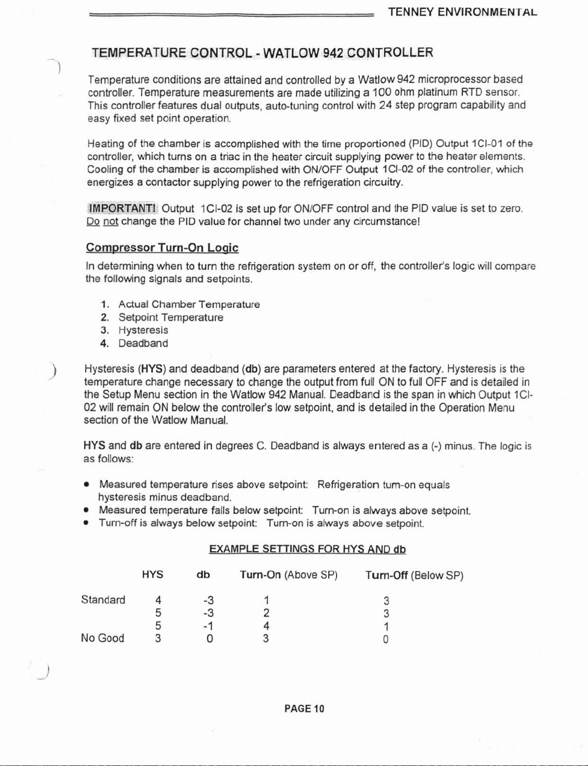
Measuredtemperature rises above setpoint: Refrigerationturn-on equals
hysteresisminus deadband.
Measuredtemperature falls belowsetpoint: Turn-on is always above setpoint.
Turn-off is always below setpoint: Turn-on is always above setpoint.
EXAMPLE SETTINGS
FOR
HYSAND db
HYS
d
b Turn-On (Above SP) Turn-Off (BelowSP)
Standard 4
-3
1
5
-3
2
5
-1
4
No Good
3
0
3
PAGE
10

TENNEY
ENVIRONMENTAL
Chambers are shippedwith
HYS
=
4, and
db
=
-
3, asshown onthe top line inthe above
)
examples. It is unlikelya change to these settings will be required. Fortunately,these settings
are not subject to "coldstardefault, andwill remainvalid afler a powerinterruption. They are
held in EEROM, not battery-backedRAM.
The pre-programmedconfigurationof theWatlow 942
is
documentedin the Test Report.
Pleasereferto this andthe Watlow 942 usetsmanualfor complete operationaldetails. These
are found inthe Supplemental InstructionsSection.
ControllerVersions
The Watlow 942 Controller is providedinfour versionswith the following nomenclature:
1.
The basic24-step ramping control: 942A-3KDOAE00
2.
Basic plustwo events: 942A-3KD2-AE00
3.
Basicpluscommunications: 942A-3KDO-BE00
4.
Basic plus events and communications: 942A-3KD2-BE00
The nomenclatureisprintedon the backof the controller and can be seen when the chamber's
control panel isopened.
NOTE: The communications arrangementis isolated RS232lRS423,RS422, EIA-485,or IEEE.
Eachevent output is through a mechanicalrelay havingcontactsrated
6
Amps, 120or 240
VAC.
PAGE
I1

TENNEY ENVIRONMENTAL
ALARM
AND
SHUTDOWN
CIRCUIT
I
A comprehensivealarmandshutdown circuit may be providedfor multiple protection against
productoverlundertemperature and chamber overtemperature.The sensor utilizedfor
temperaturemeasurementand the Heat Limiter Fuseare normally placedat the plenum inthe
downstream airflow. This isthe most responsive area of the chamber.
Chamber Over Temoerature Protection; The following device is used.
1.
Heat Limiter
(HL)
--
TemperatureActuatedFuse (Standard)
ProductOverIUnderTernaerature Protection: The following optionaldevice may be used.
With this option, a
100
ohm platinum RTD is utilizedfor temperature measurement.
1.
Watlow
93
Controller
-
-
TempGard IV Feature
-
HighlLow Limits (Optional)
WARNING1 When Master Contactor ICONisdeenergized due toANY alarm condition
described below, power isonly removedfrom the conditioning controlcircuitry. The
instrumentationand alarm circuitry will still beenergized!
Forany questions concerningthe operationof any of the controllers describedbelow, please
referencethe appropriateuser manual locatedinthe SupplementalInstructionsSection.
CIRCUITOPERATIONS:
)
NormalConditions:
When chamber temperature
is
withinthe selectedsetpoints
the
switch (green)
ON
light is
illuminatedandthe MasterContactor ICONis energized. The contacts of ICONprovide
powerto the conditioningcontrolcircuitry. (Withthe optional alarmbuzzer
I
silence switch or
TempGard IVfeature, the NORMALlight
2LT
will illuminate. When either of these optional
features are used, the maincontrol switchwill not
be
equipped with any integrallights.)
Note:
A
spare set of ICONcontacts are providedfor the customer's closure. Itis
recommendedthat these contacts,wired to terminal blocks#I4
&
#15, be usedto energizean
active heat load if utilized.
Oaened Heat Limiter:
When a predeterminedhigh temperature limit is reachedand the Heat LimiterFuse (which
looks like a regularfuse) opens, Master Contactor ICONwill deenergizealongwith the
conditioningcontrolcircuitry.The switchOVERTEMP lightwill illuminateand the switch
ON
lightwill extinguish. (With the optionalalarm buzzer1silence switch feature, boththe red
ChamberOVERTEMPlight 3LTand redALARM light4LT will immediately illuminate, the alarm
buzzerwill sound, andthe NORMAL lightwill extinguish.) Whenthe Heat LimiterFuse opens,
it
bereplaced.
-
--
WARNING1 When replacingthe Heat Limiter Fuse, make sure all power is completely
disconnectedfrom the chamber. Open the closest main power disconnect and pullthe plug (if
provided)from the outlet.
PAGE
12

TemoGard IV Alarm
-
-
Ootional:
1
When a presettemperaturelimit is reachedwithin the Watlow 93 TempGard IV, the TGlV
alarm contacts open to deenergize MasterContactor ICON,which removespowerfrom the
conditioningcontrolcircuitry. The NORMAL light is now extinguished, the red
ALARM
light 4LT
illuminates,and the alarm buzzersounds.The redChamberOVERTEMP light 3LTwill
illuminatewhen the alarmcondition clears
and
the TempGard IValarm is clearedas detailedin
the Watlow 93 manual.
Note: The alarm buuerwithsilenceswitch isan optionalfeature for allchambers. This alarm
circuitry comes standardwith the Watlow
93
TempGard IV feature. The TempGardIV
configuration is shown in the "Watlow 93 TempGard IV ConfigurationAnd Use" section.
Svstem Reset ForAlarm Buuer
I
Silence Switch
or
Tem~GardIVO~tion
-
-
lm~ortant!
After an out of limit conditionhas been corrected, the conditioningcontrol circuits must be
restartedby momentarily pressingthe RESET button
IPB.
You must rememberto clear the
Watlow 93 alarm message.
A 1.5second timer ITC,
is
indudedin the resetcircuitto provide for automatic startwhen
poweris appliedto the chamber. This avoids the need to press the reset buttoneach time that
poweris removedand reapplied.
Alarm Buzzer
8,
Silence Switch
-
-
Ootional:
With this option the silenceswitch disables the alarm buuerwhile correctiveaction is taken.
When 1SSis activated, thewhite Silence light 5LTwill be illuminated. If the alarm buuerwas
)
disabled and the system was successfullyresetwith IPB, the alarm buzzer will nowsound to
alert the operatorto place the silence switch 1SSin it's normal(down) position.
Heatingof the chamber is accomplishedwith the time proportionedoutput ICI-01of the
Watlow
942
Controller,which tums on triac ITRCto supplypowerto the heaterelements.
These elements are open air low mass nichrome wires, which havelowthermal lagand
provide rapid responseto the controller's demands. The heater elements are isolatedfrom the
workspaceto prevent direct radiationto the product. Pleasereferencethe electricalschematic
for your particularchamber's heaterbank ratings.
PAGE
13

SINGLE STAGE REFRIGERATION SYSTEM DESCRIPTION
)
The basic single stagesystem consists of a compressor, anoilseparator (exceptfor Models
BTS.
T6S. T27, & T65). eitheran air cooled or water cooled condenser, an evaporator coil
(located
in
the chambd; conditioningsection) which is provided with a capillary (iube) type
expansiondevice, and a suction lineaccumulatorto guard against liquid refrigerantreturnto
the compressor.
Refrigerantflow is from the compressor as a hot compressed gas through the oil separatorto
the condenser. Herethe refrigerantcools and condensesto liquidform and flows through the
capillary tube to the evaporatorcooling coil inthe chamberconditioningsection. Warm
chamber air iscirculated through the cooling coil and heat exchange occurs as the liquid
refrigerantboils, vaporizes, and absorbs heat. The vaporized refrigerantreturnsto the
compressorthrough the suction lineaccumulator SLA. The cycle is repeated.
Forall units except ModelBTS, a thermostatis mountedon the suction retum line near the
compressorto monitorthe temperatureof the returngas flow. When a predeterminedhigh
temperature is reached, the thermostatwill energizean artificial loadingsolenoid, which will
injectrefrigerant through a capillary tube intothe suction side of the system. This actionwill
maintain a positivecool refrigerantflow to the compressor, preventingoverheatingof the
compressorand the discharge gas.
The basiccascadesystem consists of a low stage compressor. a high stage compressor, an
,
evaporator coil, anda cascade condenser.
The lowstage system includes an oil separator(for models with compressor motorsgreater
than
1
H.P.), a cascadecondenser, an expansiontank, and an evaporator coil (locatedinthe
chamber conditioningsection) which is providedwith a capillary (tube)type expansiondevice.
The high stage system includesan air cooled or water cooled condenser, a capillarytube
which feeds the cascade condenser, and a suction line accumulatorto guard against liquid
refrigerantreturnto the compressor.
Thefunctionof the cascadecondenserisfor the high stage refrigerantto cool and condense
the lowstage refrigerant. This permits greater system efficiency and allows lowerchamber
temperatures to be reachedthanwhat can beattainedwith a single stage system. The low
stage liquidrefrigerantfrom the cascadecondenser is metered through a capillary tube to the
evaporatorcoil. Heatexchange takes place here as the liquid refrigerantconverts to a gas and
then returnsto the low stage compressor.
A
thermostat is mountedon the suction return line near the low stage compressorto monitor
the temperature of the return gas flow. When a predeterminedhigh temperatureis reached,
the thermostatwill energizethe Artificial Loadingsolenoid 14SOL,which will injectrefrigerant
intothe suction side of the system. Itwill first enterthe expansiontank where the added
volume permitsthe chargingof additionalrefrigerantwithout increasingthe standby or
charging pressure beyondworkable limits. Refrigerantgas isthen suckedout of the expansion
tank and meteredthrough
a
capillarytube to the suction side of the low stage compressor.
)
This actionwill maintain a positivecool refrigerantflow to the compressor, preventing
..
overheatingof the compressor and the dischargegas.
A
high pressurecut-in sensor monitorsthe pressureinsidethe low stage compressor
andwill activatethe Load LimitSwitch4PS when the low stage dischargepressurereaches
280 PSIG.This will energizethe Artificial Loadingsolenoid 14SOLwhichwill inject refrigerant
into the suction side of the system as described above. Switch 4PS preventsthe compressor
from cyclingon and off inresponse to signals from the high pressurecut-out switch. 4PS will
open when pressurefalls to 240 PSIG.
For moredetailed informationon a cascade system, please referencethe sectionentitled
"ServicingCascade RefrigerationSystems".
The refrigerationsystem is providedwith several safety devices that stop the compressor(s)
from runningif conditionsexceedpreset limits. Ina cascadesystem boththe low stage and the
high stage includethese safety devices. With a low limit conditionthe HI-LO Pressure Cutout
Switch 1PS (and 2PS for cascade)will continue to automaticallyreset until sufficient pressure
develops. With a highlimit condition you must manuallv reset
1
PS (or2PS). If the compressor
continuesto trip off havethe system checked by a qualifiedrefrigerationsystem mechanic.
The possiblecauses of a high or low limit cutout are as follows:
NOTE:
The HI-LO Pressure
Cutout Switch does notapply to the Models BTS, BTC, T6S, andT6C.
HighPressure Cutout (IPS, ZPS)
-
-
Opens if a preset compressordischargepressure
is exceeded. Probablecausefor highstage cut-out is insufficientcoolingwater (water
cooled systems) or restrictedair flow (air cooledsystems). Probablecause for low stage
cutout is a malfunctionof the high stage system. 1PSRPSare typically set at 300 PSIG.
Low Pressure Cutout (IPS, 2PS)
-
-
Opens if the compressorsuction pressurefalls
below a preset value. Probablecausesare a loss of refrigerant(either stage) or restricted
air flow acrossthe evaporator(low stage). 1PSRPSare typically set at 6 inches of vacuum.
Motor Overload
- -
Opensifthe motorwindings exceed a preset temperature. Probable
causes are insufficientflow across the motor due to a refrigerant loss or a failure of the
liquidinjectionvalve providedfor suctiongas cooling. The motor overload is installed
directly inthe motorwindings and will automaticallyreset and restartthe compressorafter
the motorhas cooled.
PAGE
15

WATLOW
93
-
TEMPGARD IV CONFIGURATION
&
USE
(Optional)
As an option, your chamber may include the TempGard IV feature with the Watlow
93
Controller. The circuit operationdescription is explained
in
the Alarm And Shutdown Circuit
section of this manual. This configuration sectionserves as a brief referenceguide. For
complete details of the Watlow
93
Controller, please reference the user manual.
When properly configured,the lower display of the controlwill beblank and the upper display
will show the actualtemperature as measuredby the control's RTDsensor, when conditions
are within the alarm settings. If an out of limit conditionoccurs, the lowerdisplay will flash "HI"
or
"LO
depending on the particularfault.
IMPORTANT:
For
All Models
-
When the alarm hascleared you mustpressthe
RESET pushbutton
1
PB.
To configurethe control to performas describedabove, power it up and select the setup menu
by pressingthe UPlDown arrow keys simultaneously. Pressingthe
"M"
key then allows you to
scrollthrough the set up parameters.
Setthese parametersin accordancewith the table below. The parameterwill appear inthe
lower display; the UPIDOWN keysare usedto set the value.
11
rL
1
Set low range limit
1
-100
11
)
11
r
H
I
Set high range limit
1
+ZOO
*
11
WATLOW
93
-
TEMPGARD
IV:
SETUP MENU
II
rtd
I
Select sensor curve
I
JIS
II
PARAMETER
In
c-F
2
HSA
LAt
Scrollthroughthose parametersnot listed above; their settinas are immaterial.After scrolling
throughall parameters, the controlwill revert to the "OPERATE"mode. Inthis mode, usethe
"M
key to scroll to the ALO (alarmlow) parameter and use the UPIDOWNarrow keys to set
the desiredlow alarm value. Then, use the
"M"
key to scroll to theAH1 (alarmhigh) parameter
anduse the UPIDOWN keys to set the desired high limitvalue.
FUNCTION
Select
type
of sensor
Select temperature units
DefineOutput
2
Select hysteresis
Select latch
I
nonlatch
dSP
Aftersettingthese values, continue scrollingwith the
"M"
key untilthe controlsetpointappears
J
inthe lower display. After a few seconds, this display will go blank.
E
rtd
C
--
--
PrA
I
nLA
Other values maybeentered depending onthe range
of
the chamber.
Select display
~-
Pro

BOOST HEAT (Optional)
)
As anoption,your chamber may be equippedwith the boost heatfeature which includes extra
heaters to provide rapid increasesintemperature. The boost heatwill automaticallyturn on if a
preset time delay relay times out, indicatingthat the desired temperature has not been
achieved.
As output ICI-01of the controller energizes the mainheater bank, ICI-01will at the same time
energize a time delay relay. When this relaytimes out itwill energizea mercury relay,which
provides powerto the boost heaters.
A
mechanical contactorisalso providedwhich has it's
contactswired into the power supply line to the boost heaters. This contactoris providedto
deenergizethe heaters in the event of an over temperature condition.
BOOST COOLING (Optional)
USING LIQUID NITROGEN
or
CARBON DIOXIDE
As an option, your chamber may be equippedwith a boost coolingsystem which is activated
by anevent output from the Watlow 942 Controller. Cooling is achieved by injectingeither LN,
or CO,, dependingon the option purchased, intothe chamber through a solenoid valve. To
activatethe system the event must be turned on as explained inthe Watlow
942
Controller
manual.
Event No.
1
is generally used for this function. However, a referencetable defining the function
of each event is affixed to the control panelof each chamber. Pleasecheck this table before
)
operatingthe chamber.
Onceenabledthrough the event, the coolingwill turn on if
a
demandfor cooling existsfor a
preset time period.
A
timer connectedto the time proportioned outputof the controller "times
out" and energizesthe cooling solenoid valve if the output is 100percent "ON" indicatinga
needfor additionalcooling.
When the desired temperature is attained andthe controller heat output begins to turn on, the
boostcoolingfunction will cease.
LN, systemsare provided with a manually set flow adjustingvalve providedto allow for
adjustingthe flow to avoid incomplete evaporation at varying LN, supply pressures.
A
setting
of 4 turns open generally provides good performanceat a supply pressureof 20 to 25 PSIG.
This valve may be readjustedas necessaryto accommodatethe supply pressureat the end
usepoint.
PAGE
17

PURGEAIR SYSTEM (Optional)
USING COMPRESSEDAIR or NITROGEN
As an option, your chambermay beequippedwith a dry air or
GN,
purge system which is
activatedby an event output from the Watlow
942
Controller. To usethe system, the event
must be turned on as explained inthe Watlow
942
manual. EventNo.
2
is generally used for
this function. However,a referencetable definingthe function of each event is affixed to the
controlpanelof each chamber. Pleasecheck this table before operatingthe chamber.
A meteringvalve and flowmeter is suppliedas part of the system to establishthe design purge
flow. Thevalve should be adjusteduntilthe indicatedflow is about
300
cubic feet per hour.
The
GN,
purge system isprimarilyutilizedto providean inert atmospherewhich minimizesthe
buildupof moistureand prevents condensationon the product undertest. Eliminatingthe
oxygen inthe chamberair helps preventcorrosionof the productundertest.
A drierisprovidedfor compressed air purgesystems. This systemrequires a supply of
relatively oil free compressed air at a minimumpressureof
80
PSIG. This air isdriedby a bin
tower heatless, self regeneratingdryer and is introducedinto the chamber through a solenoid
valve.
CHART
RECORDER
(optional)
As an option, your chamber may beprovidedwith either a circularor strip type chart recorder
)
to recordtemperature versus time. This recorderistypically a one pentype which also digitally
displays the processvalue. A
100
ohm platinumRTD is used for temperature measurement
and is nomlally placedinthe plenum of the chamber.
The recorderconfigurationis documented inthe Test Report, which is locatedin the
Supplementallnst~ctionsSection. For completedetails on the operationof the recorder
pleasereferencethe recorder's user's manualwhich is located in the same section.

DATA COMMUNICATIONS (Optional)
)
As an option, your chamber may include data communicationswith the maincontroller's serial
port. when employed, either a bata Communications manualor a Computer Interfacemanual
will be included in the Supplemental InstructionsSection. As a reference, the availabledata
types are listedand brieflydescribed below. Pleasecontact a Tenney Sales Engineerfor more
information.
RS232C
I
RS423A: Both interfacesare compatibleand use 3 wires: a single transmit wire; a
single receive wire; and a commonline. The maximumwire length is 50 feet. Only a single
chamber may be connectedto your computer. Data signals are measuredas plus and minus
12 volts to commonwith RS232C, and plus and minus 5 vylts to common with RS423A.
RS422A: This interfaceuses 5 wires: a transmit pair; a receive pair; and a commonline. Up
to tenchambersmay be connectedto your computeron a multi-dropnetworkup to 4,000 feet
long. Datasignals ineach pair are measured as a plus or minus 5 volt differential.
EIA-485: This interface uses only 2 wires. Bothwires are usedfor transmittingand receiving
data, andtherefore, only one device may talk at a time. Up to 10chambers may be connected
to your computer on a multi-dropnetworkupto 4,000 feet long. Data signals are measuredas
a
plus or minus 5 volt differential.An EIA-485 card must beinstalledfor signal conversion.
IEEE-488: This is a parallel multi-dropinterfacewith several control and data lines. Each
device connectedmust be set to a uniqueaddress. Data from othertest devices may also be
collected. Sincethe controllerswe use only have serialcommunications, an IEEE-488to serial
)
converter cardis installed in the chamber. Maximum cable lengthis approximately
33
feet for
all devices.
PAGE
19
LinkTenn SOFTWARE (Optional)
)
Welcome to anotheruniqueoptionalfeature developed by Tenney Environmental.
LinkTennsoftware is designedto operate on a remote computer system and provide complete
control of Tenney Environmentaltest chambers. This is accomplishedby communicating
through a RS232lRS422interfacewith the VersaTenn
Ill
or Watlow 942, 945, and 988
Controllers.Upto ten chambers may be controlledfrom one computerwith RS422 interface.
LinkTennsoftware isprovidedboth in a DOSformat and in a Windows format on
3%
inch
diskettes. Inthe DOSformat, "LinkTennII" software is designed to work with the VersaTenn Ill
Controller, and "LinkTenn 942" software is designedto work with the Watlow 942 Controller. In
the Windows format, "LinkTennForWindows"software is designed to work with the
VersaTenn
Ill
andthe Watlow 942. 945, and 988 Controllers.
The hardwareand software requirementsto run LinkTennsoftware in bothformats are listed
below.
DOS
Format: LinkTenn
II
&
LinkTenn942
1.
Any DOS basedcomputer
2. 256K of RAMmemory
3. CGA graphics card
4. DOS2.0 or higher
5.
RS232computer interfacefor singlechamber control
6.
RS422computer interfacefor multiplechamber control
7.
With IEEE-488communications, a National InstrumentsPC2A or compatiblecard
)
Windows
Format:
LinkTenn ForWindows
1.
Computerwith 486 processor or higher
2. Eight Megof harddrive memory
3. Eight Megof RAM memory
4. Windows 3.X operating system or higher
5. RS232computer interfacefor single chamber control
6. RS422computer interface for multiplechamber control
7.
Currently notavailableto work with IEEE-488communications
A sample menu display screen entitled"ProgramControl"from the LinkTennFor Windows
program, is provided in the SupplementalInstructionsSection. This screen shows some of the
uniquefeatures incorporatedintothe programalongwith sample setpoints.
When LinkTennsoftware is providedineitherformat, a correspondingLinkTennUser'sManual
will be providedinthe SupplementalInstructionsSection.

I
CNNCY ENVlKUNNlClV
IHL
CHAMBER
OPERATION
)
To operatethe chamber, turn onthe powersource to the chamber and close all chamber
circuit breakers.The display of the Watlow 942 should now be illuminated. Enterthe desired
temperature programor manualsetpoints as explained inthe Watlow 942 user's manual.
Closethe Power On switch ISS. The greenON light should beilluminated.
If your chamber includes the optionalWatlow 93 Controllerwith TempGard IV feature, set this
controller'shighllow temperature limits at this time. Referto the "AlarmAnd Shutdown Circuit"
descriptionandthe "TempGardIV ConfigurationAnd Use Instructions"for further details.
Forthose chamberswhich includeany other options, please referto the appropriate "optional"
manualsectionsfor a detailed operationdescription.
IMPORTANT
NOTE1
For complete programmingandlor operating instructionson any of the
controllers, electrical
I
mechanicalcomponents, or optional equipment, you must referto their
operatingmanuals includedwith your Tenney Environmentalmanual.
PAGE
21
This manual suits for next models
12
Table of contents
Other Tenney Test Equipment manuals

Popular Test Equipment manuals by other brands


Redtech
Redtech TRAILERteck T05 user manual

Venmar
Venmar AVS Constructo 1.0 HRV user guide

Test Instrument Solutions
Test Instrument Solutions SafetyPAT operating manual

Hanna Instruments
Hanna Instruments HI 38078 instruction manual

Kistler
Kistler 5495C Series instruction manual

Waygate Technologies
Waygate Technologies DM5E Basic quick start guide

StoneL
StoneL DeviceNet CK464002A manual

Seica
Seica RAPID 220 Site preparation guide

Kingfisher
Kingfisher KI7400 Series Training manual

Kurth Electronic
Kurth Electronic CCTS-03 operating manual

SMART
SMART KANAAD SBT XTREME 3G Series user manual

Agilent Technologies
Agilent Technologies BERT Serial Getting started