Tens Twin Stim Plus User manual

FORTHE
INSTRUCTIONMANUAL
INSTRUCTIONMANUAL
Twin StimPlus
R
FDA 510K
DIGITALTENS/EMS
Distributed by:
V1.0
PDF created with FinePrint pdfFactorytrial version http://www.pdffactory.com

1
INDEX
1. General Description .............................................. 2
2. Introduction ........................................................... 2
3. Cautions................................................................. 4
4. Warnings ................................................................ 6
5. Contraindications.................................................. 6
6. Adverse Reactions ................................................ 6
7. Construction.......................................................... 7
8. Technical Specifications ....................................... 9
9. Replaceable Parts ................................................. 13
10 Accessories .......................................................... 13
11. Graphic Symbols ................................................... 14
12. Operating Instructions ......................................... 14
13. ParameterControls .............................................. 15
14. Attachment of Electrode Lead Wires .................. 18
15. Lead Wire Maintenance ........................................ 18
16. Electrode Options ................................................. 19
17. Electrode Placement ............................................. 19
18. Tips for Skin Care ................................................. 20
19. Application ofReusable self
adhesiveelectrodes ............................................. 20
20. Adjusting the Controls ......................................... 22
21. BatteryInformation ............................................... 30
22. Maintenance, Transportation, and
Storage of the Device ........................................... 31
23. Safety-Technical Controls .................................... 32
24. Malfunctions .......................................................... 32
25. Conformityto SafetyStandards .......................... 33
26. Warranty................................................................. 33
Chapter Contents Page
PDF created with FinePrint pdfFactorytrial version http://www.pdffactory.com

32
HOWTENSWORKS
Thereis nothing magic”aboutTranscutaneousElectricalNerve
Stimulation (TENS).TENSisintended to be used torelievepain.The
TENSunit sendscomfortable impulsesthroughtheskinthatstimulate
thenerve(ornerves)inthetreatmentarea. In manycases, this
stimulation will greatlyreduceor eliminatethe painsensationthe
patient feels. Pain relief varies by individual patient, mode selected
for therapy, and the type of pain. In many patients, the reduction or
elimination of pain lasts longer than the actual period of stimulation
(sometimes as much as threeto fourtimes longer). In others, painis
onlymodified whilestimulation actuallyoccurs. You may discuss
thiswithyour physician or therapist.
EXPLANATION OF EMS
ElectricalMuscleStimulationisan internationally accepted and proven
wayoftreatingmuscularinjuries. Itworks bysendingelectronic
pulses tothe muscle needing treatment; thiscauses the muscleto
exercise passively.
It is a product derived fromthe square waveform, originally invented
by John Faraday in 1831. Through the square wave pattern it is able
to work directly on musclemotor neurons.The TwinStim has low
frequencyand this in conjunction with the square wave pattern
allows direct work on musclegroupings. This is being widely used in
hospitals andsports clinicsfor the treatmentofmuscular injuries
and for the re-education of paralyzed muscles, to prevent atrophy in
affected muscles and improving muscle tone and blood circulation.
HOW EMS WORKS
1. Relaxation of muscle spasms
2. Prevention or retardation of disuse atrophy
3. Increasing local blood circulation
4. Musclere-education
5. Immediate post-surgical stimulation of calf muscles to prevent
venousthrombosis
6. Maintaining or increasing range of motion
TheEMS units sendcomfortableimpulsesthroughtheskin that
stimulate the nervesinthe treatmentarea. Whenthemusclereceives
this signal it contracts as if thebrain has sent thesignal itself. As the
Chapter 1:GENERALDESCRIPTION
The Twin Stim Plus Digital TENS/EMS is abattery operated pulse
generator that sends electricalimpulses electrodes to the body and
reachthe nervesandunderlyingmuscle group. This unit is a
combination stimulator ofTENSandEMS which canbeused for
musclestimulation and painrelief.The deviceisprovided withtwo
controllableoutputchannels,eachindependent ofeachother.An
electrode pair can be connectedtoeach outputchannel.Theintensity
controlsareprotectedbya capto avoidaccidentaltouch.The settings
are controlled by pressbuttons.
Chapter2 : INTRODUCTION
EXPLANATION OF PAIN
Painis awarning systemand the body’smethod oftelling usthat
something iswrong. Painisimportant; withoutit abnormal conditions
may go undetected,causing damage or injury tovitalparts ofour
bodies.
Eventhoughpain is anecessary warning signalof trauma or
malfunction in the body,nature may have gone too far in its design.
Aside fromits value in diagnosis, long-lasting persistent pain serves
no useful purpose. Pain does not begin until codedmessage travels
to the brain where it is decoded, analyzed, and then reacted to. The
painmessage travels fromthe injured area along the small nerves
leadingto the spinal cord. Herethemessage is switchedto different
nerves that travel up the spinal cord to the brain. The pain message
is then interpreted, referred backand the pain is felt.
EXPLANATION OF TENS
Transcutaneous ElectricalNerve Stimulationis a non-invasive, drug-
free method of controlling pain. TENS uses tiny electrical impulses
sent through theskin to nerves to modify your pain perception.
TENS does not cure any physiological problem; it only helps control
the pain. TENS does not workfor everyone; however,in most
patients it is effective in reducing or eliminatingthe pain, allowing for
areturn to normal activity.
PDF created with FinePrint pdfFactorytrial version http://www.pdffactory.com

54
8. Thisdevice shouldnotbeusedwhiledriving,operating machinery,
close to water, or during any activity in which involuntary muscle
contractions may put the user at undue riskof injury.
9. Turn the TENS off before applying or removing electrodes.
10.Isolated cases of skin irritation may occur at the site of electrode
placement following long termapplication. If this occurs,
discontinue useand consult your physician.
11. If TENS therapy becomes ineffective or unpleasant, stimulation
should be discontinued until its useis re-evaluatedby a physician
12.Keep thisdevice out of the reachofchildren.
13.The device has no AP/APG protection.
Do not use it in the presence of explosive atmosphere and
flammablemixture.
EMS
1. Federal law(USA) restrictsthis device to sale by or on the order
ofaphysician
2. Safetyof powered muscle stimulators for useduring pregnancy
has notbeen established.
3. Caution should be used for patients with suspected or diagnosed
heart problems.
4. Caution should be used for patients with suspected or diagnosed
epilepsy.
5. Caution shouldbe used in the presenceof the following:
a. Whenthereisa tendencytohemorrhage followingacutetrauma
orfracture;
b. Following recentsurgicalprocedureswhen muscle
contraction may disrupt the healing process;
c. Over the menstruating or pregnant uterus; and
d. Over areas of the skinwhich lacknormal sensation.
6. Somepatients may experience skin irritation or hypersensitivity
due to the electrical stimulation or electrical conductive medium.
The irritation can usually be reduced by using an alternate
conductive medium, or alternate electrode placement.
7. Electrode placement and stimulation settings should be based on
the guidanceof the prescribing practitioner.
8. Powered muscle stimulators shouldbe kept out of the reachof
children.
9. Powered muscle stimulators should be used onlywiththe leads
and electrodes recommended for useby the manufacturer.
signal strength increases, the muscle flexes as in physical exercise.
Then when the pulse ceases, the muscle relaxesand the cycle
starts overagain, (Stimulation,Contraction and Relaxation.) Powered
muscle stimulators shouldonly be used under medical supervision
foradjunctivetherapyforthetreatmentof medicaldiseasesand
conditions.
IMPORTANT SAFETY INFORMATION
Read instruction manual beforeoperation. Be suretocomplywith all
CAUTIONS”and WARNINGS”in themanual.Failuretofollow
instructions can causeharm touser or device.
Chapter 3 : CAUTIONS
TENS
1. Federal law(USA) restrictsthis device to sale by or on the order
ofaphysician.
2. Do not use this device for undiagnosed pain syndromes until
consulting aphysician.
3. Patients with an implanted electronicdevice, suchas acardiac
pacemaker,implanteddefibrillator, orany other metallicorelectronic
device shouldnotundergo TENStreatment withoutfirst consulting
adoctor.
4. Patients with heart disease, epilepsy, cancer or any other health
condition should not undergo TENS treatment without first
consulting aphysician.
5. Stimulation delivered by this device may be sufficient to cause
electrocution. Electricalcurrent of thismagnitude mustnot flow
through the thorax or across the chestbecauseit may causea
cardiac arrhythmia.
6. Do not place electrodes on thefront of the throat as spasmof the
Laryngeal and Pharyngeal muscle may occur. Stimulation over
the carotidsinus (neck region) may close the airways, make
breathing difficult,and may have adverseeffects on the heart
rhythm or blood pressure.
7. Do not place electrodeson your head or at any sites that may
causethe electricalcurrentto flow transcerebrally (through the
head).
PDF created with FinePrint pdfFactorytrial version http://www.pdffactory.com
76
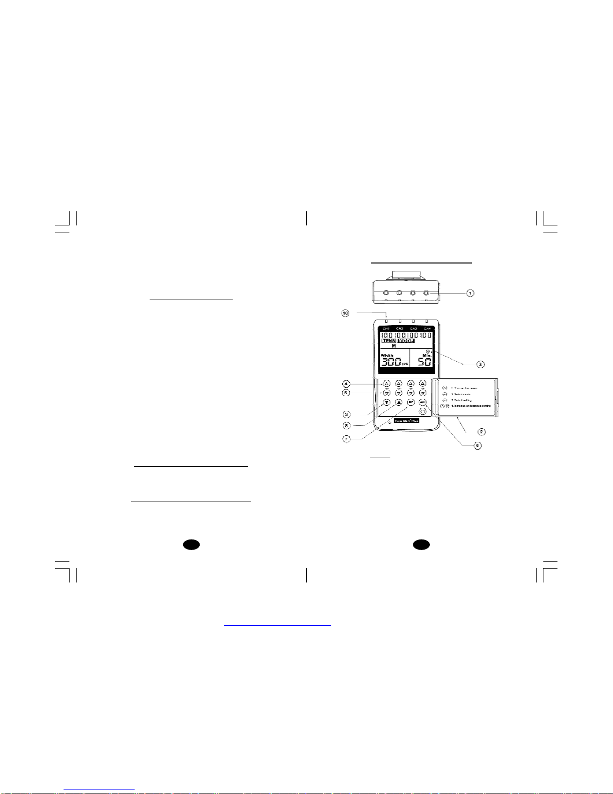
Chapter 7 : CONSTRUCTION
FRONT
(1)LEADCONNECTOR
(2)PANELCOVER
(3)LIQUIDCRYSTALDISPLAY
(4)INTENSITY INCREASECONTROL
(5)INTENSITY DECREASECONTROL
(6)MODECONTROL
(7)SETCONTROL
(8)INCREMENT CONTROL
(9)DECREMENT CONTROL
(10)LED
10.Portable powered muscle stimulators shouldnot be used while
driving, operating machinery, or during any activityin which
involuntary muscle contractions mayput the user at undue risk of
injury.
Chapter 4 : WARNINGS
1. The long-term effects of chronic electrical stimulation are
unknown.
2. Stimulation should not be applied over the carotid sinus nerves,
particularlyin patientswithaknown sensitivity to the carotid
sinusreflex.
3. Stimulation should not be applied over the neck or mouth. Severe
spasm of the laryngeal and pharyngeal musclesmay occur and
the contractionsmay be strong enough toclose the airway or
cause difficulty in breathing.
4. Stimulation should not be applied transthoracically in that the
introduction of electricalcurrent into the heart maycause cardiac
arrhythmias.
5. Stimulation should not be applied transcerebrally.
6. Stimulationshould notbeapplied overswollen,infected,orinflamed
areas or skin eruptions, e.g., phlebitis, thrombophlebitis, varicose
veins, etc.
7. Stimulation should notbe applied over,or inproximityto,cancerous
lesions.
Chapter5: CONTRAINDICATION
Electrical stimulatorsshouldnotbe usedon patients withcardiac
demand pacemakers.
Chapter 6:ADVERSE REACTIONS
Skin irritation and burns beneath the electrodes have been reported
with the use of electrical stimulators. If irritation occurs, discontinue
useand consultyour physician.
PDF created with FinePrint pdfFactorytrial version http://www.pdffactory.com

98
Chapter 8 : TECHNICAL SPECIFICATIONS
The technicalspecificationdetails of TwinStim Plus areas follows:
MECHANISM TECHNICALDESCRIPTION
01 Channel Four, isolated between channels
02 PulseAmplitude Adjustable, 0-100 mA peak into 500 ohm
load eachchannel.
03 Wave Form Asymmetrical Bi-Phasic Square Pulse
04 Voltage 0 to 50V (Load: 500 ohm)
05 Power source Four AAbatteries
06 Size 13.8cm(L) x7.8cm(W)x2.8cm(H)
07 Weight 425 gramswithbattery.
08 Pulse Rate Adjustable, from 2 to 150 Hz, 1 Hz/step
09 PulseWidth Adjustable, from50 to 300 microseconds,
10 µs/step
10 OnTime Adjustable, 2~90 seconds ,1Sec./step
11 Off Time Adjustable, 0~90 seconds ,1Sec./step
12 RampTime Adjustable, 1~8 seconds, 1 Sec./ step, The
On”timewill increase and decrease in the
setting value.
13 Mode Five TENS Modes: B(Burst), N(Normal),M
(Modulation),SD1( Strength Duration), SD2
Three EMS Modes:C(Constant)S
(Synchronous),A(Alternate)
14 Burst Mode Burst rate: Adjustable, 0.5 ~ 5Hz
Pulse width adjustable, 50~300µs
Frequency fixed = 100 Hz
15 NormalMode The pulse rate and pulsewidthare
adjustable. It generates continuous
stimulation based on the setting value.
16 ModulationMode Modulation mode is acombination of pulse
rate and pulse width modulation. The pulse
BACK
BACK
(11) BATTERYCASE
(12) BELTCLIP
SIDE
PDF created with FinePrint pdfFactorytrial version http://www.pdffactory.com

1110
20 Synchronous Stimulation of both channelsoccurs
Mode (S) synchronously. The ON”time including
Ramp Up”and Ramp Down”time.
Therefore, thesetting of ONTimeshouldbe
noless thantwo times ofthe Ramp”time in
this mode.
ONTIME≥Ramp up+ Ramp down
21 Alternate The stimulation ofthe CH2 will occur after
Mode(A) the 1st contraction of CH1 is completed. In
thismode,thesettingof ONTimeshouldbe
no less than two times of the Ramp”time.
TheOFFTimeshouldbe equalormorethan
theONTime.
ONTIME≥Rampup+Rampdown
OFFTIME≥ONTIME
22 Timer TwoAdjustable timers, from1 to 60 minutes
orContinuous. Adjustable in 1 minute each
step from1 to 15 minutes, and 5 minutes
eachstep from 15to 60 minutes. Treatment
time countdownautomatically.
23 Patient This unitcan store 60 sets of operation
ComplianceMeter records.Total recorded timeis999 hours.
24 LowBattery Alow battery indicatorwillshow upwhen
Indicator the battery is low.
25 Operating Temperature:0°~40°C
Condition Relative Humidity: 30%~75%
Atmosphere Pressure : 700Hpa~1060Hpa
26 Remark Theremay be up to a +/-5% tolerance of all
parameters and +/-20% tolerance of
amplitude & voltage.
rate and width are automatically varied in a
cycle pattern. The pulse width is decreased
by 50%fromits originalsetting in 0.5second,
then the pulserate is decreased by 50%
fromitsoriginal setting in 0.5 second.Total
cycle time is 1 second. In this mode, pulse
rate(2-150Hz) and pulsewidth(50-300 µs)
are fullyadjustable.
17 SD1Mode TheSD1(Strength-Duration) mode consists
of automaticmodulation intensity and pulse
widthin 40% range. The intensityis always
increasingwhile the pulsewidthis decreasing
andvice-versa. The intensity is decreased by
40%while the pulse widthisincreased by40%
in5seconds.Inthenext5seconds, the intensity
is increasedby40% while the pulse widthis
decreased by 40%.Total cycle time is 10
seconds.Pulserate( 2~150Hz)andpulse width
(50~300µs) are fullyadjustable.
18 SD2Mode TheSD2(Strength-Duration) mode consists
of automaticmodulation intensity and pulse
widthin 70% range. The intensityis always
increasing whilethe pulsewidth is decreasing
and vice-versa. The intensity is decreased by
70% while the pulse widthis increased by 70%
in5seconds.In thenext5seconds, theintensity
is increasedby70% while the pulse widthis
decreased by 70%.Total cycle time is 10
seconds.Pulse rate(2~150Hz) and pulse width
(50~300µs)are fully adjustable.
19 Constant Constantstimulation basedonsetting value.
Mode (C) Only pulse width, pulse rate and timer are
adjustableinthis mode. Constant”is equal
to the Normal”modeofa TENSunit.
PDF created with FinePrint pdfFactorytrial version http://www.pdffactory.com

1312
Chapter 9 : REPLACEABLE PARTS
The replaceable parts and accessories ofTwinStim PlusDigital
TENS/EMS devices are as given below –
Except leads, electrodes,battery and battery case cover,please do
nottry toreplacethe other partsof adevice.
PARTS
01 LEADWIRES
02 ELECTRODES
03 1.5 BATTERY,TYPEAA
04 BELTCLIP
05 BATTERYCASECOVER
06 LEAD CONNECTOR
07 MAINPCB
08 INTENSITY KNOB
09 LCDCOVER
10 INTENSITYCONTROLCOVER
Chapter 10 : ACCESSORIES
Each TwinStim PlusDigitalTENS/EMS comescompletewithstandard
accessoriesand the standard labels asgiven below:
I. Accessories
REF.NO. DESCRIPTION Q’TY
1. TKS4040 40 X40 mm Adhesive Electrodes 8 pieces
2. KE-26 Electrodes Leads 4 pieces
3. AA Battery 4 piece
4. Instruction Manual 1 piece
5. Carrying Case 1 piece
The waveforms of the TENS modes are asfollows.
1. Burst
2.Normal
3. Modulation
4. SD1 (Strength-Duration)
5. SD2 (Strength-Duration)
PDF created with FinePrint pdfFactorytrial version http://www.pdffactory.com

1514
6) Select the mode and settings as directed by your physician.
7) There are 4sets of intensitybuttons,whichcorrelateto eachof
the 4channels.Slowlyincrease or decreasethe intensity as
directed by your physician by pressing the up or downIntensity
buttons. (Please put a picture of them) Press the up arrowbutton
to increase intensityandpress thedown arrowbuttontodecrease
intensity.
8) After treatment, turn the device off by pressing the (ON/OFF
button)
Chapter 13 : PARAMETER CONTROLS
PULSEDURATION
Widerpulse duration settings will deliver stronger stimulation for any
givenintensitysetting.As mentioned in theControls section,by
usingacombinationof intensityandpulse duration,it is felt that
various pulsewidths are capableofstimulating differentgroups of
nervefibres.
The wider pulse duration is needed to recruit motor fibres,whereas
the narrowpulseduration is used on the more sensory fibres.The
choice of which pulse duration to use is partiallydependent upon the
Treatment Mode andProtocol selected.
PULSERATE
The Pulse Rate (hertz or pulses per second) chosendepends greatly
upon the type of electrode placement given to the patient.
When using contiguous and dermatomeelectrode placements (i.e.
stimulating directly through the area of pain or localized enervation),
aquick pulserate (settinggreater than80Hzonthe Pulse Rate
Control)is desired.Thepatient shouldnotperceiveindividual pulses
but rather have the sensation ofsteady continuous stimulation.
Whenusing point treatments, it has beensuggested that slowpulses
be utilized (lessthan 10Hz). With thissetting the patientshould be
able toslightly perceive individual pulses.
Whenusing multipleelectrodeplacement strategies,suchas
combinations ofpointandcontiguouselectrodeplacements, the
quicker pulseratesare suggested.
II. LABEL The label attached to the back of
device contains important
information about this device-
model, supply voltage and caution.
Please do not remove.
Chapter 11 : GRAPHIC SYMBOLS
1. Degreeof Electrical Protection BF
2. Do not insert the plug intoAC power supplysocket.
3. Timer
4. LowBattery
5. Increment
6. Decrement
Chapter 12: OPERATING INSTRUCTIONS
1) Insert the AAbattery into the device’sbattery compartment.
Make sure to remove the plasticsealon the AAbattery.Line up
the positive and negative terminals on the battery withtheir
corresponding terminalsin the device.
2) Insert the lead wiresintothe lead wire socketson top of the
device.
3) Open the electrode package. Then insert each lead wire pin into
the pigtail of the electrodes
4) Placethe electrode on your body as directed by your physician.
5) Pressthe (ON/OFF button) to turn on the device.
PDF created with FinePrint pdfFactorytrial version http://www.pdffactory.com

1716
minutes of such atetanizedmuscular contraction willgenerally break
thespasm. In all cases, ifthepatientcomplains thatthe stimulation is
uncomfortable, reduce intensityand/or ceasestimulation.
TIME DURATION
The onset ofpain relief should occur shortly after theintensitysetting
has been determined. However, in somecases, pain relief may take
aslong as 30minutes to achieve, especially whenusing point
electrode placementsand slow pulse rates.
TENS units aretypicallyoperatedfor long periodsoftime, witha
minimumof 20 –30 minutes andinsome post-operationprotocols, as
long as 36 hours.
In general, pain relief will diminish within 30minutes of the cessation
ofstimulation.Painrelief obtained throughpointelectrode placements
may lastlonger (perhapsbecauseof the presence ofendorphins).
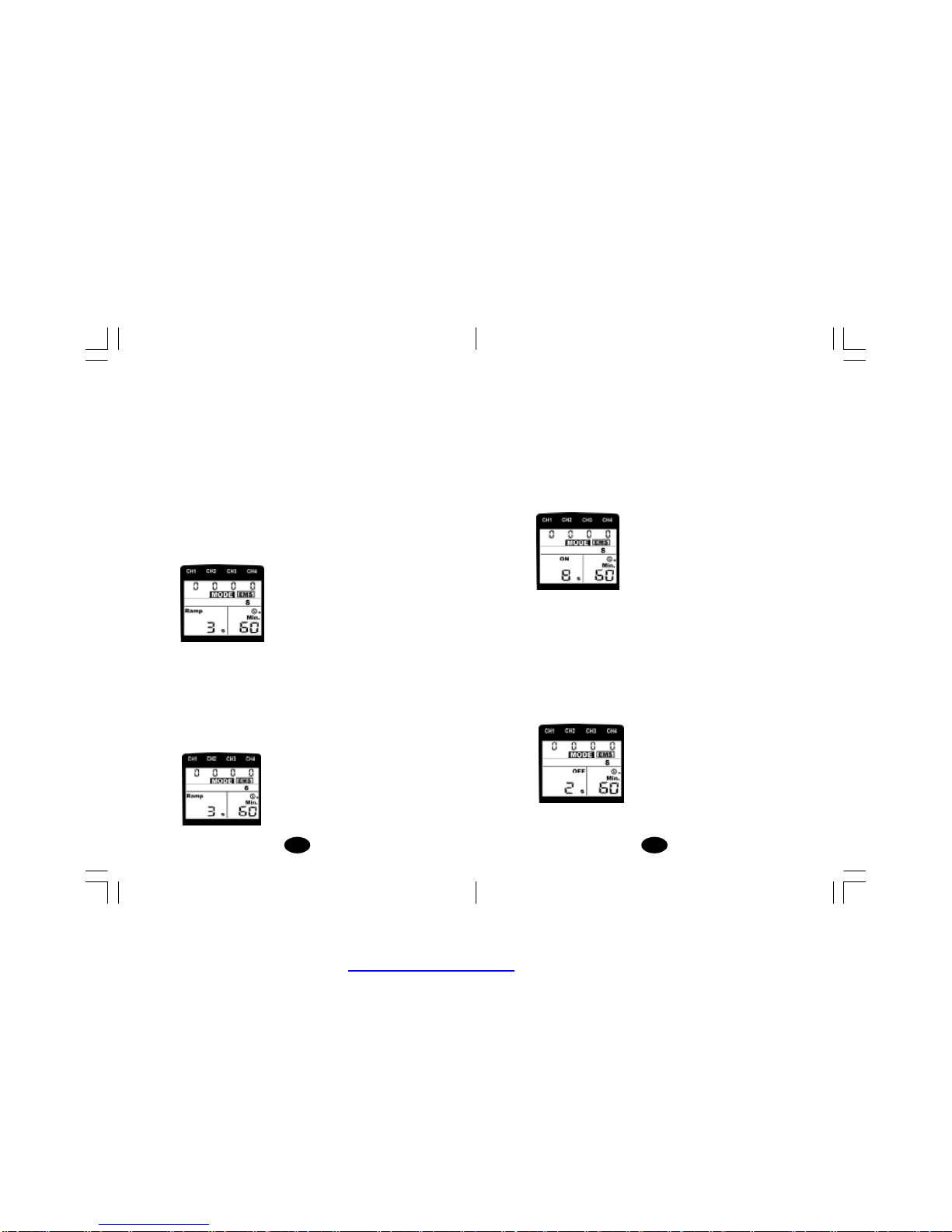
CONTRACTION / RELAXATION
The contraction time and relaxation timeof EMS is adjustable.
Stimulation will continue at the setting contraction timeand cease
alsoat thesetting relaxation time. Then the cycle starts over again –
Stimulation, Contraction and Relaxation.
RAMP
In orderto achievea comfortable exercise and avoid startlebecause
of electrical shock, each contraction course may be ramped so that
thesignalcomeson gradually and smoothly.The intensityofelectrical
current will reach the setting level within the Ramp time, however, it
can not reach the expected levelif the contraction timeis less than
theramp time.
OUTPUT MODE
The output of both channels are adjustable. It can be in the pattern
of synchronous or alternate. Stimulation of both channels will occur
atthesametime when simultaneouspattern isselected.At alternating
mode, the stimulation of the CH2 will occur after the 1st contraction
of CH1 is finished.
Despite above recommendations, these individualpatientsmay
requireslight variations of theabove settings, according to thenature
oftheircondition.
TREATMENTMODE
NormalorConventional TENSoffersthepractitionerscompletecontrol
over all the various treatment parameters of the instrument.
Burst Modeis analogous to theLow Rate TENStechniqueexcept the
lowfrequencyindividualpulsesare replaced by individual bursts”
of 7-10 individualpulses. Itis thus acombination of Conventional
TENS andLow Rate TENS. In Burst Mode, the treatment frequency
is adjustable at the range between 0.5Hz –5Hz.
ModulatedModeattemptsto preventnerve accommodationby
continuously cycling thetreatment intensity. When using Modulated
Mode increasethe intensityonlywhen the unitis atthe maximum
intensity of the modulation cycle. If the intensity is increased during
alow intensity period of thecycle, thepatient may turn up the control
very slowly, sothat they may feelthe intensity any higher.
INTENSITY
Each patient responds differently to different levelsof intensity, due
to varying degrees oftissue resistance, enervation, skinthickness,
etc. Intensityinstructionsaretherefore limited tothe following settings:
Perception –The intensity isincreased so that the patient can feel
the stimulation, but there is not any muscular contraction.
Slight Contraction –Intensity is increasedto abarelyvisiblemuscular
contraction thatisnot strong enough tomove ajoint.When using
lowpulse rate settings, thiswill showasindividual twitches. At
higher pulse rates there will simplybe increased muscle tension.
Strong muscular contraction is typically notused inTENS therapy.
However,muscular contraction may be useful if the pain involves a
cramped or spasticmuscle.The TENS can be used as atraditional
muscle stimulator in the circumstances to quickly break the spasm.
Useaquickpulse rate, wide pulse duration and setthe intensityto
visiblecontraction(still within patienttolerance).Twentyorthirty
PDF created with FinePrint pdfFactorytrial version http://www.pdffactory.com

1918
Chapter 16 : ELECTRODE OPTIONS
Theelectrodes aredisposableandshould beroutinely replaced
when they starttolosetheiradhesive nature.If you are unsure of
your electrode adhesive properties, order replacementelectrodes.
Replacement electrodes shouldbere-orderedthrough oronthe
advice of your physician to ensure proper quality. Follow application
proceduresoutlinedinelectrode packing,tomaintain optimalstimulation
and to prevent skinirritation.
Chapter17:ELECTRODEPLACEMENT
The placement of electrodes can be one of the most important
parametersinachieving success withTENSor EMStherapy.Of
utmost importance isthe willingness ofthe physician to trythe various
styles of electrodeplacement to find which methodbest fits the
needs of the individual patient.
Every patientresponds to electrical stimulation differentlyand their
needsmay vary from the conventionalsettings suggested here. If
theinitialresults are notpositive, speak toyourphysicianabout
alternative stimulation settings and/or electrode placements. Once
an acceptable placement has been achieved, mark downthe
electrodes sites and the settings, so the patient can easily continue
treatment at home.
Chapter 14 : ATTACHMENT OF ELECTRODE LEAD
WIRES
The wires provided with the system insert into the jack sockets
located on top ofthe device.Holding the insulatedportion of the
connector, pushthe plug end of the wire into one ofthe jacks (see
drawing);one or two setsofwires maybeused.
After connecting the wiresto the stimulator, attacheachwire to
an electrode. Use care when you plug and unplug the wires.
Jerking the wire instead ofholding the insulated connector body
may causewire breakage.
CAUTION
Donotinsert theplugofthe patientlead wire intoanyACpower
supplysocket.
Chapter 15: LEAD WIREMAINTENANCE
Clean the wiresby wiping with adampcloth.Coating them lightly
withtalcumpowder willreducetangling and prolong life.
PDF created with FinePrint pdfFactorytrial version http://www.pdffactory.com

2120
Removal
1. Turn offthe unitprior to removing the electrodes.
2. Lift at the edge of electrodesand peel; do not pullon the lead
wires becauseit may damage the electrodes.
3. Place the electrodes on the liner and remove the lead wire by
twisting and pulling at the same time.
Care and Storage
1. Between uses,store the electrodesinthe resealablebag ina
cooldry place.
2 . It may be helpful to improve repeated application by spreading a
fewdrops ofcoldwater over the adhesive and turn the surface
up to air dry. Over Saturation with water will reduce the adhesive
properties.
Important
1. Do not apply to broken skin.
2. The electrodes shouldbe discarded and re-ordered fromyour
physician when they are no longer adhering.
3. The electrodes are intended for single patientuseonly.
4. Ifirritation occurs,discontinue useand consultyour physician.
5. Read the instructions for useofself-adhesive electrodes before
application.
Chapter 18: TIPS FOR SKIN CARE
Toavoidskinirritation,especiallyif you have sensitive skin, follow
thesesuggestions:
1. Washthe area of skin where you will be placing the electrodes,
using mild soap and water before applying electrodes,and after
taking themoff. Be sure to rinse soap off thoroughly and dry skin
well.
2. Excess hairmaybeclippedwith scissors; donotshave stimulation
area.
3. Wipe the area with the skin preparation your physician has
recommended. Letthisdry.Apply electrodes as directed.
4. Many skin problems arisefromthe pulling stress”fromadhesive
patchesthatare excessivelystretched across the skinduring
application. Toprevent this, applyelectrodesfromcentreoutward;
avoidstretching over the skin.
5. Tominimize pulling stress”,tape extra lengths of lead wires to
the skinin a loop to prevent tugging on electrodes.
6. When removing electrodes, always remove by pulling in the
direction ofhairgrowth.
7. It may be helpful to rub skin lotion on electrode placement area
when not wearingelectrodes.
8. Never applyelectrodes over irritated or broken skin.
Chapter 19: APPLICATION OF RE-USABLE SELF
ADHESIVEELECTRODES
Application
1. Clean and dry the skin at the prescribed area thoroughly with
soap and water prior toapplication ofelectrodes.
2. Insertthe lead wire intothe pinconnector on the pre-wired
electrodes.
3. Remove the electrodes fromthe protective liner and apply the
electrodes firmly to the treatmentsite. Make sure that the unit is
turned offprior to applying the electrodes.
PDF created with FinePrint pdfFactorytrial version http://www.pdffactory.com

2322
4. Mode Control
Thereare 5 TENSmodes(B, N,M, SD1,SD2) and2 EMS modes
(S,A)available.Themodecanbeselectedbypressingthe Mode”
control. When aTENS mode is selected, the LCDshows TENS”
on the top. When EMS mode is selected, the LCD shows EMS”
on the top.
5. Set Control
By pressing the Set”control, you may enter the setting you
intend to make adjustment. You may start to set the value by
pressing the Increment”and Decrement”controlswhen the
value is flashing.
6. IncrementControl
This button controls the increase of settings. When pressingthis
button, the parameter will increase.
7. Decrement Control
This button controls the decrease ofparameter. When pressing
this button,the parameter will decrease.
8.Timer
The unit has a timer of 1-60minutes and Continuous. It can be
adjusted by pressing the Set”and Increment”or Decrement”
controls. Thetreatment timewillcountdown automaticallyinone
minute increments. Its outputwillbe shut off when timeis up.
9.Low Battery Indicator
Alow battery sign will show up on the liquid crystal display
whenit needs tobe replaced as soon as possible. The unit may
continue to operate for afewmore hoursdepends on the
setting intensity level.
Chapter 20 : ADJUSTING THE CONTROLS
1. Panel Cover:
Alid coversthe controlsforselecting mode and adjustingsettings.
Your medical professional may wish to set these controlsfor you
and request that you leave the cover in place.
2. Power On/Off Controls and Intensity Controls:
Power of the unit can be turned on by pressing the power control.
The intensity level can be increased or decreased by pressingthe
intensity controls. Intensity level can be adjusted in 100 steps
linearly.
There are 4 leds on the top of unit showing the output of electrical
current.They willbe light up when there isoutput.
3. Lead Connector
Connectionof the electrodes ismade withthefour-leadconnector
(lead wires). The device must be switched offbefore connecting
the cables. Electrodes must be pressed firmly on the skin.
PDF created with FinePrint pdfFactorytrial version http://www.pdffactory.com

2524
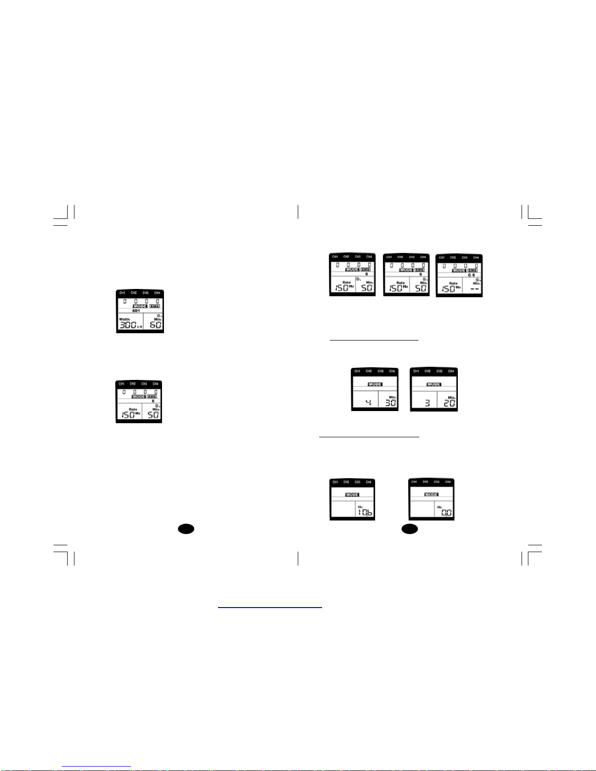
d. SetPulse Rate
Pulse rate is adjustable from2Hz to 150 Hz . Press SET”
control toenter thismenu,then press Increment”or Decrement”
toadjust the setting. Unlessotherwiseinstructed, turn the
pulserate control tothe 70-120 Hz range.
e. SetTimer
There are twoadjustable timers available. The left timer
controlling the treatment timeof CH1and CH2.
The right timer controlling the treatment timeof CH3 & CH4.
The treatment time is adjustable from1 to60 minutes or C
(Continuous). Press SET”control to enter this menu, then
press Increment”or Decrement”to adjust the setting.
Press Increment”control when the timer shows60 minutes,
it will be switched to continuous stimulation. Two timers can
be set in the sameway.
11.Steps to Set a EMSProgram
The settings can be adjusted according to the following steps.
f. Turn on the Power
After the electrodes are placed firmly on skin and the lead
wires are plugged in the socket of device, press the ON/OFF
Continuous
10.Steps to Set aTENSProgram
The settings can be adjusted according to the following steps.
a. Turn on the power
After the electrodes are placed firmly on skin and the lead
wiresare plugged inthe socketofdevice, turn the on/off
controlclockwise. The menu willreveal on LCD. Notice the
indication of power and function on the LCD.
b. Select a Mode
Select a mode by pressing the Mode”control. The mode you
selected will showup on the top of liquid crystal display. There
are 5 modes of your option including –B(Burst), M(Normal), M
(Modulation),SD1andSD2.WhenaTENSmodeis selected,it
shows TENS”on the top of liquidcrystal display.
After amode is selected, always press Set”toenter next
setting, andpress Incrementor Decrement”toadjust its value.
c. Set Pulse Width
PulseWidth is adjustablefrom50 uS to 300 uS. Press SET”
controltoenter thismenu,then press Increment”or Decrement”
toadjust thesetting. If noinstructions regardingthepulse width
are given in therapy, set the control to the suggested
70-120 uS setting.
RightTimerLeft Timer
PDF created with FinePrint pdfFactorytrial version http://www.pdffactory.com
2726
i. SetOnTime
TheOn Timecontrols the time of stimulation. By pressing the
Set”control, the contraction timecan be adjusted. Both
channels’stimulation iscycled on and offby the contraction
and relaxation settings. The range is adjustablefrom
2secondsto90 seconds.
As the ON”time including the ramp up and ramp down time,
the settingof itshouldbeno less thantwo timesofthe Ramp”
time.(ONTIME ≥Ramp up + Ramp down)
j. Set Off Time
The Off Time controlsthe time of relaxation. By pressing the
SET”control, the relaxation time can be adjusted. Both
channels’stimulation iscycled on and offby the contraction
and relaxation settings. Therange is adjustable from 0 second
to90 seconds.
InAlternate mode,theOFFTimeshouldbeequal ormore than
theONTime.(OFF TIME≥ONTIME)
k. Set Pulse Width
button. The menu will reveal on LCD. Notice the indication of
power and function on the LCD.
g. Select Mode
There are three EMS modes of option, C(Constant) S
(Synchronous) or A Alternate). Select a mode by pressingthe
Mode”control. Whenan EMS modeis selected, the LCD
shows EMS”on the top.
After amode isselected, press SET”controltoenter next
setting. You may adjust the setting only when it isflashing.
Then press the Increment”or Decrement”control to change
the settings.
h. SetRampTime
Theramp time controls the time ofoutput currentthat increase
from0 to the setting level, and from the setting value to 0.
When the ramp time is set, each contraction may be ramped
up and down inorder that the signalscomeon and comeoff
gradually and smoothly. The ramp time is adjustable from
1to8seconds.
PDF created with FinePrint pdfFactorytrial version http://www.pdffactory.com
2928
12. ComplianceMeter
This unit can store 60 sets of operation records. Total treatment
time up to 999 hours can be stored.
Check &Delete Individual Record
Press Mode”control and turn on the power simultaneously.
The LCD will show the number of records and operation time.
Press the Increment”and Decrement button to check each
record.
Todelete arecord, press SET”control for 3seconds.
Check & DeleteAccumulative Record
Atthe individual records menu, press Mode”control toswitch
to accumulative record menu. Press the SET”controlfirst, then
press the Mode”control simultaneously for 3 seconds and all of
the recordswill be deleted followed by abeeper sound.
PulseWidth is adjustablefrom50 uS to 300 uS. Press SET”
control toenter this menu, then press Increment”or
Decrement”to adjust the setting. If no instructions regarding
the pulse width are given intherapy, set the control tothe
suggested 70-120 uS setting.
l. SetPulse Rate
Pulse rate is adjustable from2Hz to 150 Hz . Press SET”
control toenter this menu, then press Increment”or
Decrement”to adjust the setting. Unless otherwise instructed,
turn the pulseratecontroltothe 70-120 Hz range.
m.SetTimer
There are twoadjustable timers available. The left timer
controlling the treatment timeof CH1and CH2.
The right timer controlling the treatment time of CH3 & CH4.
The treatment time is adjustable from1 to60 minutes or C
(Continuous). Press SET”control to enter this menu, then
press Increment”or Decrement”to adjust the setting.
Press Increment”control when the timer shows 60 minutes,
it willbe switched tocontinuous stimulation.
Whenyou usethe EMS treatment, theintensity level will flash
whenitisat OFF”time (relaxation). Theintensity levelcannot
be adjusted untilit works again at ON”time.
Continuous
Left Timer RightTimer
PDF created with FinePrint pdfFactorytrial version http://www.pdffactory.com
3130
BATTERY CHARGING
(1) Plug the charger into any working 110 or 220/240v mainselectrical
outlet. The use of any attachment not supplied with the charger
may resultin the risk of fire, electric shock, or injury to persons.
(2) Followthe battery manufacturer’sinstructions for charging time.
(3) After the battery manufacturer’srecommended charging time
has been completed, unplug the charger and remove the battery.
(4) Batteries shouldalwaysbe stored in afullycharged state.
Toensure optimumbattery performance, follow these guidelines:
(a) Although overcharging the batteries for up to24 hourswill
not damage them,repeated overcharging may decrease
usefulbattery life.
(b) Alwaysstore batteries intheircharged condition. After a
batteryhasbeen discharged,rechargeit assoonas possible.
If the battery is stored more than 60 days, it may need to be
recharged.
(c) Do not short the terminals of the battery. This will cause the
battery to get hot and can cause permanent damage. Avoid
storing the batteriesinyour pocketor pursewhere the
terminals may accidentallycome into contactwith coins,
keys or any metal objects.
(d) WARNINGS:
1. Do not attempt tocharge any other types ofbatteries in
your charger, other than rechargeable batteries made for
your charger.Other types of batteries may leak or burst.
2. Donotincineratethe rechargeablebattery as itmay explode!
Chapter 22 : MAINTENANCE, TRANSPORTATION
ANDSTORAGE OF THE DEVICE
1. Non-flammable cleaningsolution issuitable forcleaning the device.
Note:Donot smokeorworkwithopen lights (for example,candles,
etc.)when working withflammable liquids.
2. Stains and spotscan be removed with a cleaning agent.
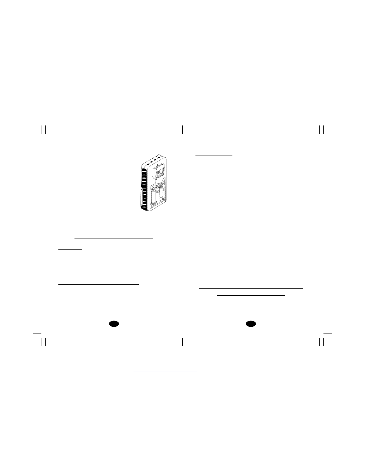
13. Check/Replace the Battery:
Over time, inorder to ensure the functional
safetyofthe unit,changing the battery is
necessary.
1. Make sure that both intensity controlsare
switched tooff position.
2. Slide the battery compartment cover and
open.
3. Remove the battery fromthe compartment.
4. Insertthebattery into thecompartment. Note
the polarityindicated on the battery and in
the compartment.
5. Replace the battery compartment cover
and presstoclose.
Chapter 21: BATTERY INFORMATION
PRECATIONS
1. Removebattery ifequipmentisnotlikelytobeusedforsome time.
2. Please recyclethe used battery inaccordancewithdomestic
regulation.
3. Do notthrow the used battery intofire.
Ifyou use rechargeablebatteries, please follow the instructions.
RECHARGEABLE BATTERIES (NOTINCLUDED)
Prior tothe useofanew unit, the rechargeablebattery shouldbe
charged accordingtothe battery manufacturer’s instructions. Before
usingthebattery charger,readall instructions andcautionary
markings on the battery and in this instruction manual.
After being stored for 60 days or more,the batteries may losetheir
charge. After long periodsof storage, batteries shouldbe charged
prior touse.
PDF created with FinePrint pdfFactorytrial version http://www.pdffactory.com

3332
3. Do notsubmerge thedevice in liquidsor expose ittolarge amounts
ofwater.
4. Return the deviceto the carrying boxwithsponge foamto ensure
that the unit is well-protected before transportation.
5. If thedeviceisnot to beusedfor a longperiod of time, removethe
batteries fromthebattery compartment (acid may leak fromused
batteries and damage the device).Put the device and
accessories in carrying box and keep it in cool dry place.
6. The packed TENS/ EMS device shouldbe stored and transported
under the temperature range of -20°C ~ + 60°C, relative humidity
20%~ 95%, atmosphere pressure 500 hPa~ 1060 hPa.
Chapter23:SAFETY-TECHNICALCONTROLS
For safety reasons, reviewthe following checklist beforeusing
your TwinStim PlusDigitalTENS/EMS
1.Checkthe devicefor external damage.
- deformation of the housing.
- damaged or defective output sockets.
2.Checkthe device for defective operating elements.
- legibility of inscriptions and labels.
-make sure the inscriptionsand labels are not distorted.
3.Checkthe usabilityof accessories.
-patient cable undamaged.
- electrodes undamaged.
-Battery isnotcorroded
Please consult your distributor if there are any problems with device
andaccessories.
Chapter 24 : MALFUNCTIONS
Should anymalfunctions occurwhile usingtheTwin Stim Plus
DigitalTENS/EMS,check
The Twin Stim Plus DigitalTENS/EMS devices are in compliance
with the EN 60601-1-2:2001and EN 60601-1:1990+A1:1993+A2:
1995+A13:1996 safetystandards.
Chapter 26 : WARRANTY
All Twin Stim Plus Digital TENS/EMS models carry a warranty of
one yearfrom the date of delivery. The warranty applies to the
stimulator only and covers both parts and labour relating thereto.
The warrantydoes notapplytodamageresultingfromfailure to
followthe operatinginstructions, accidents, abuse, alterationor
disassemblyby unauthorized personnel.
- whether the parameters are set to the appropriate formof therapy.
Adjust the control correctly.
- whether the cable is correctly connected to the device. The cables
should be inserted completely into the sockets.
- whether the LCD revealsthe menu.If necessary,insert anew
battery.
-forpossibledamage to thecable. Change thecableifanydamage
is detected.
*If there isany other problem,please return the device to your
distributor. Do not try torepairadefective device.
Chapter 25: CONFORMITY TO SAFETY
STANDARDS
PDF created with FinePrint pdfFactorytrial version http://www.pdffactory.com

PDF created with FinePrint pdfFactorytrial version http://www.pdffactory.com
Table of contents
Other Tens Medical Equipment manuals

Popular Medical Equipment manuals by other brands


Getinge
Getinge Arjohuntleigh Nimbus 3 Professional Instructions for use

Mettler Electronics
Mettler Electronics Sonicator 730 Maintenance manual

Pressalit Care
Pressalit Care R1100 Mounting instruction

Denas MS
Denas MS DENAS-T operating manual

bort medical
bort medical ActiveColor quick guide

AccuVein
AccuVein AV400 user manual


