Tense Motivity Guide

Motivity v1.3 Technical Documentation
Technical Documentation Motivity
Status: Draft
Firmware Version : v1.3
Hardware Version : PIR Snr. 141023
Order umber: MOTX
Technical Details:
Power Supply Min. 21 VDC, Max. 31 VDC, provided by the
K X bus line
Maximum Power Consumption 300 mW
Bus Power Consumption Class 30mA
Fan-In Model TP1-256
Connection to the bus via: TBD
Operating Temperatures -5 ºC to +45 ºC
Maximum Humidity 93% relative humidity, no moisture
condensation
Type Of Protection (E 60529) IP20
Protective Separation Device Group 3
Dimensions (w x h x d) (mm) TBD
©Tense BVBA 15/03/17 1

Motivity v1.3 Technical Documentation
Functional Description
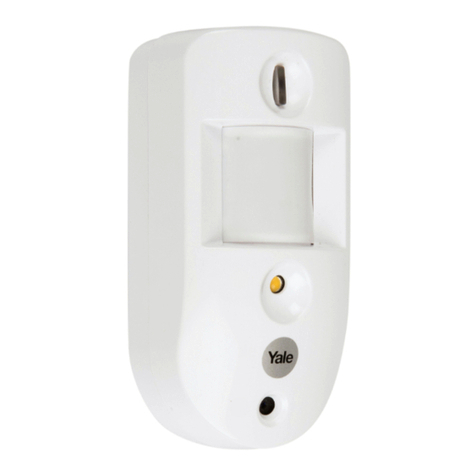
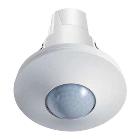
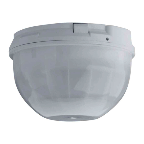
The Motivity is a Motion Detector with optional additional sensors
Its functions are:
•Master/Slave Mode possible
•(Optional) Internal Temperature Sensor with correction
•(Optional) Internal Light Sensor with correction
•Up to 4 different Output Actions available
◦Output: switching, dimming, recalling scenes, 1 or 2 Byte unsigned
◦With switch-off delay
◦Light dependent
◦Activation of objects at runtime, e.g. for day/night mode
◦Ventilation Control
•Blocking object
This functionality is further made complete by some functional modules
• Scene Module
• Basic Logic Functions
• Timers
• Up/Down Counters
• Thermostat
The functions and parameters are explained in more detail hereafter.
©Tense BVBA 15/03/17 2

Motivity v1.3 Technical Documentation
The parameters are divided into 5 Parts
1. Configuration
Here you can set some general settings.
2. Output
Define up to 4 actions that have to be performed upon a motion event, possibly filtered
by other variables.
3. Sensors
Configure some sensor settings
4. Temperature
Contains the settings of the internal temperature sensor, as well as those for the
thermostat.
5. Modules
Activate additional functionality that comes with each switch. Currently supported:
◦Scene Module, supporting eight scenes with eight actuators(1 Bit/1Byte/2Byte
supported)
◦Basic Logic Module (A D/OR functions), consisting of five Logic Channels that
each have up to five 1-Bit inputs
◦Timers, up to four
◦Up/Down Counters, up to four
Updatable Software
All the products of Tense can be updated with new internal Software (firmware). To
install new software, just use the latest K X database from our website. When the version of
the K X product database does not match the one inside the device, then ETS will
automatically install the new software into the device. This update can take a while (at least 10
minutes) depending on the other traffic on the K X bus.
You can use both full and partial download. When the new firmware is already installed, the
ETS will just send the parameters.
However, if you use “unload” then also the software will be erased, and will be downloaded the
next time ETS wants to configure the device.
ote that you never can destroy a device with this procedure. However, should
a download of the firmware fail, then it might be that the device becomes
unresponsive. To recover from this situation, hold the programming button
while powering the device.
©Tense BVBA 15/03/17 3

Motivity v1.3 Technical Documentation
Installation
Risk of electrocution
Only skilled electricians can carry out installation and commissioning of
the device. Otherwise, there is a risk of fire and electrocution. Observe
the regulations valid in the country of use, as well as the K X guidelines.
To be installed indoors.
1. Remove power from the K X bus.
2. Connect the bus coupler with the K X bus using the K X bus connection terminal.
Connect the red bus wire to the red terminal (+) and the black bus wire to the black
terminal (–).
3. The bus coupler fits in a standard size 6 -installation box .Use two screws to fix the bus
coupler. Make sure the mounting is level and that the “TOP ” marking on the PCB ↑
points upwards.
4. Plug the front onto the bus coupler. Make sure that the “TOP ” marking on the PCB ↑
(backside of the front) points upwards.
5. Power the K X bus.
©Tense BVBA 15/03/17 4

Motivity v1.3 Technical Documentation
Commissioning
First, download the appropriate product databases from www.tense.be and import it into the
ETS.
If you want to avoid a download of the firmware the first time, you can use the firmware
version that matches the preprogrammed firmware. You find the version of the
preprogrammed software version on the label.
1. Remove the front.
2. To trigger the programming mode, hold a magnet near the head. Make sure the red
programming LED lights up.
3. In the ETS, add the device and assign the physical address.
4. Program the physical address. Make sure the red programming LED turns off.
5. Replug the front.
6. In the ETS, select the appropriate parameters and assign the group addresses.
7. Download the application program to the device.
©Tense BVBA 15/03/17 5

Motivity v1.3 Technical Documentation
General Settings
In this page you can set some general settings, e.g. whether a Light or Temperature sensor is
attached to the Motivity base electronics.
You can also specify the “Read on Init delay time”. The “Read On Init” flag is a communication
object flag new for System B devices. If you set this flag on a communication object, then the
intensity will issue read requests upon power-up, to make sure that its status values are up-
to-date.
Set this value to a time, where you are certain that every bus device is up and running and will
answer read requests. In that way you assure that the internal states of the Intensity
correspond with the actual values.
List of available Communication Objects and Parameters:
©Tense BVBA 15/03/17 6
Name Value Range Comment
Light Sensor Present Yes/No whether Light Sensor is attached
Temperature Sensor Present Yes/No whether Temperature Sensor is attached
Read On Init Delay[s 4 – 255 Time To wait before reading objects with the ROI flag

Motivity v1.3 Technical Documentation
Output
The settings under Output let you define which action should be executed when Motion is
detected, and what should happen when the switch-off delay is reached.
General
If this Motivity only forwards its motion detection events to another K X device that decides
which action to take, you should set this Motivity into Slave Mode. However, if this device acts
as the Master, you can set here which action to perform when motion is detected. Up to 4
different actions can be defined, which can be (de)activated on the fly.
Here you can also specity whether the Motivity should control the ventilation (see further).
You can also enable a blocking object, which will cause the Motivity to ignore any motion
detection in the output object. ote that if blocking has been set after motion has been
detected, then no OFF action will be taken., The other functions (e.g. Under sensors) are not
affected by this setting and bus communication is still possible.
List of the parameters and communication objects:
Communication Objects :
©Tense BVBA 15/03/17 7
Name Value Range Comment
Mode Master / Slave Select between Master/Slave Mode
Enable Blocking Object Yes/No
Number of Output Objects 1 to 4
Enable Ventilation Yes/No Enable ventilation logic
enable a general blocking object which will
enable/disable all output objects
Number of possible actions this motivity must perform
upon motion detection
No Name I/O DPT Flags Use
1 Blocking Object I DPT1.2 WCTUI enable/disable all output objects
6 Slave Motion Detector Input I DPT1.1 WCTUI
Input detection status from Slave Motion
Detector

Motivity v1.3 Technical Documentation
Output
With each Output Action you can specify which action to perform when motion is detected,
allowing you to e.g.
–switch on/off a 1-Bit actuator
–adjust the dimming to a fixed absolute value
–recall a scene
–send an (unsigned) 1 or 2 Byte value
–etc...
You can also specify a switch-off delay. This is the time after the last detection that the Motivity
will wait to perform the turn off action.
It's also possible to make the action depending on a maximum brightness value. When the
light level, from the internal or external sensor, is above this threshold, then the motivity will
ignore the motion event.
Output Actions can be selected at runtime. This allows you to specify a different behaviour at a
different time or in different conditions. When an Output Action is deactivated, it might be
useful to turn off the light sources it controls. If this is necessary, set “Send OFF on
deactivation” to “Yes”.
The safety pause parameter will disable the motion detection for 2 seconds. This might be
useful if a different light source is in the field of the detector, and switching on of this light
sources causes the detector to trigger on it.
List of parameters and communication objects:
©Tense BVBA 15/03/17
No Name I/O DPT Flags Use
7 Switch Value 1bit O DPT1.1 CT 1 bit Output from Output Object1
7 Value 1 Byte Scaling O DPT5.1 CT
7 Value 1 Byte O DPT5.10 CT Unsigned 1 Byte Output from Output Object1
7 Scene O DPT17.1 CT Scene value from Output Object1
7 Value 2 Byte O DPT7.1 CT Unsigned 2 Byte Output from Output Object1
8 External Lux Value I DPT9.4 CW Value if external light sensor is used
9 Safety Pause Input I DPT1.1 CW Input for ignoring briefly motion detector
10 Object Selection I DPT1.1 CW Input for (de)activating the Output Object
1 Byte Scaling Output from Output Object1,
typically used for dimming

Motivity v1.3 Technical Documentation
The objects of the second Output Object start at 11. There is a spacing of 4 objects between
each Output Action.
©Tense BVBA 15/03/17 9
Name
1 second, 1 minute, 1 Hour
Yes/No
0-750
Yes/No
Yes/No
Yes/No
Value Range Comment
Value Type
1bit, 1 Byte Scaling[0-100% , 1
Byte unsigned [0-255 , Scene
[1-64 , 2 Byte unsigned [0-
65535 type of value to send with this output action
ON Value to send on Start depending on value type value to send when motion is detected
OFF Value to send at End of
Switch Off Delay depending on value type
value to send when switch off delay has
elapsed
Base Switch Off Delay Time Base for Switch Off Delay Time
Time Factor Switch Off Delay 1 to 240
factor to multiply Time Base Switch Off
Delay Time
Depending on Brightness Value
the action is depending on the (internal or
external)lux value
Lux Threshold
threshold value under which the light is
switched on
Use internal sensor
Use internal brightness sensor, or a value
from an external sensor, received over the
bus
Use Safety Pause
ignore motion detector input for 2 seconds
after a '1' telegram was received on the
“Safety Pause Input” object
Activation
Always Active, Active on 1,
Active on 0 (de)activate this Output Action
Send OFF Value upon deactivation
Send OFF value when Output Action is
active and deselected

Motivity v1.3 Technical Documentation
Ventilation
The motivity is able to control ventilation. After a person has entered a room, ventilation can
be started, after a certain amount of time has elapsed. The person has to be present for a
minimum time, at least 5 seconds. If the minimum presence time is bigger than the delay
time, then the delay time will be automatically extended to be equal to the minimum presence
time. ote that the blocking object will block this when active.
List of the parameters and communication objects:
©Tense BVBA 15/03/17 10
No Name I/O DPT Flags Use
23 Ventilation Switch O DPT1.1 CT Ventilation Switch object
Name Value Range Comment
5 to 240
1 to 240 Duration of the venilation
5 to 240
Ventilation Delay
Time[seconds
time to wait after the first detection to start the
ventilation
Ventilation Duration time [x10
seconds
Ventilation Minimum
Presence time[seconds
Minimum time between the first detection and last
detection to start the ventilation

Motivity v1.3 Technical Documentation
Sensors
To obtain direc feedback about the Motion Detector and Brightness.
Motion Detector
If you only want to capture the state of the (debounced) Motion Detection sensor (e.g. For
Slave – Master setup) then you can use the “Detector Status” object.
You can also enable the Green Feedback LED for feedback.
©Tense BVBA 15/03/17 11
Name Value Range Comment
Detector Status
Enable Feedback LED Yes/No
Do Not Send, Send 1 on every
detection, Send 1 at start
Detection, 0 at end
whether to use a fixed scene value, or use
one from an external communication
object
turn on the (Green) LED when the motion
detector senses motion
No Name I/O DPT Flags Use
5 Motion Detector Status O DPT1.1 CT motion detector status

Motivity v1.3 Technical Documentation
Brightness Sensor
To get information about the measured light intensity, you can query the brightness sensor.
Due to tolerances in the brightness sensor electronics, it might be necessary to correct the
measured value.
If you want to switch on a certain brightness level (e.g for determing the difference between
day/night), you can use the Threshold value switch communication object. A
If the Lux Hysteresis is different from 0, then the switch object will be set to 0 only when the
measured light level is below the threshold minus hysteresis value.
©Tense BVBA 15/03/17 12
Name Value Range Comment
Correction for Lux Value -127,128 correct on the measured brightness value
0-60 send the lux value cyclically
0-750 threshold level
Hysteresis 0-255 hysteresys value
Send at least every …
minute(s)
Threshold value for switch
object
No Name I/O DPT Flags Use
3 Lux Value O DPT9.4 CRT measured brightness value
4 Lux Threshold Switch O DPT1.1 CT threshold value has been surpassed

Motivity v1.3 Technical Documentation
Temperature
All temperatures are in °C.
Internal Sensor
The Intensity contains an internal Temperature sensor which is sampled every 5
seconds. It measures temperatures from -40 °C to 125 °C. By using the parameter
Temperature Correction you can correct the measured value when necessary. The temperature
value can be send onto the bus after a cyclical time or when the new measured value differs
too much from a previous value. The latter case will also reset the cyclical timer.
List of the parameters and communication objects:
©Tense BVBA 15/03/17 13
No Name I/O DPT Flags Use
2 Internal Temperature O DPT9.1 RCT (Corrected) Internal Measured Temperature
Name Value Range Comment
-50 to 50
0 to 50
0 to 60
Temperature Correction ( x
0.1 °C)
correction on measured value, in tenth of a degree
(range -5° to +5°)
Send at a deviation of ... ( x
0.1 °C)
send temperature automatically onto the bus as soon as
the difference between the last sent temperature is
bigger than the current temperature + or - this
parameter. Set to 0 to disable.
Send at least every ...
minute(s)
send temperature periodically onto the bus. Set to 0 to
disable.

Motivity v1.3 Technical Documentation
Thermostat
You can use a built-in thermostat to control the climate of your room. Heating, Cooling,
Heating + Cooling with manual or automatic switch is supported. If a wait time is specified,
then the thermostat will wait that period after a switch occurred before controlling the
heating/cooling.
The status of heating/cooling can be monitored by the heating/cooling mode feedback, or by
the corresponding bits in the RHCC Status Feedback object.
The method for controling the climate can be 2-Step switching , PI continuous or PI switching.
When switching is selected, an output object Heating (or Cooling) switch will appear. In the
other case, a Heating (or Cooling) value will make you able to control your heating/cooling
equipment.
4 Modes are supported :
•Comfort
•Standby
•ight
•Building Protection (a.k.a. Heat/Frost Protection)
The modes can be set over the HVAC object (DPT 20.102) , or over the corresponding 1 Bit
object. The Presence or Window open object can also alter the current mode.
For a schematic overview of how the current HVAC mode is determined, see below.
©Tense BVBA 15/03/17 14

Motivity v1.3 Technical Documentation
©Tense BVBA 15/03/17 15

Motivity v1.3 Technical Documentation
Feedback about the current mode can be obtained through the mode feedback status objects
or through the HVAC status object (DPT_HVACStatus).
Status and rrors
Through the RHCC Status Feedback object (DPT 22.101) you can track the status of the
thermostat. Following bits are implemented:
Bit0 : Fault
Bit7 : Heating Disabled
Bit8 : HeatCool mode
Bit11 : Cooling Disabled
Bit12 : DewPoint status
Bit13 : FrostAlarm
Bit14 : Overheat Alarm
Bit 6 (Controller Status) of the HVAC Status object indicates whether the thermostat is
actively heating/cooling.
The “Dewing Point Alarm” will disable the cooling immediately.
Frost Alarm will be set if the temperature drops below the frost protection setpoint. Overheat
alarm when temperature is higher than the heat protection temperature.
Setpoint
The setpoint can be controlled in 2 ways
•by writing a new temperature to the Setpoint object
•Using the Setpoint Adjustment object. This can either be a floating point offset or a 1
bit switch object. The latter you can use to change the setpoint using button input.
Writing a 0(up) will increase the offset with 0,5 K, writing a 1 (Down) will decrease it.
You can also limit the values that are written directly to the setpoint object, by setting “ ew
Setpoint within Adjustment bounds” to “Yes”.
Feedback of the setpoint , or the adjustment, will be given through the feedback objects.
Actual Temperature
It's possible to use an external temperature sensor to determine the actual temperature of the
room, optionally for a certain proportion. Feedback on the calculated temperature can be
obtained through the “Actual Temperature Feedback” object.
©Tense BVBA 15/03/17 16

Motivity v1.3 Technical Documentation
©Tense BVBA 15/03/17 17
Name Value Range Comment
Control Mode
Wait Time after switch (min) 0 – 240
Default HVAC Mode
Yes/No
Proportion external sensor
Maximum Adjustment up 0°C to 7°C
Maximum Adjustment down 0°C to 7°C
Setpoint Adjustment Over
Setpoint Comfort Mode 5°C – 40 °C Setpoint in HVAC mode “Comfort”
Standby Offset +/- 0°C - 7°C Offset applied to Setpoint in Standby Mode
Night Offset +/- 0°C - 7°C Offset applied to Setpoint in Night Mode
5°C – 40 °C Setpoint in HVAC mode “Building Protection”
Control Method
Hysteresis Up 0.3 °C to 2.0 °C
Hysteresis Up 0.3 °C to 2.0 °C
PWM Cycle Time (minutes) 1 to 60 minutes
Cooling System
Heating System
Proportional Range (x 0.1K) 10 – 50 the proportional factor of the PI controller
Reset Time (minutes) 0 – 240 the reset time of the PI controller
Heating / Cooling / Heating
and Cooling (Automatic
Switch) / Heating and
Cooling (Manual Switch)
Heating or Cooling Mode of the thermostat. When
using the manual switch you can use the
heating/cooling Selection object to set the desired
mode(0 = Cooling, 1 = Heating). When the switch
is done automatically, then the current mode will
depend on the current temperature. When lower
than the heating setpoint, heating mode will be
activated. Higher than the cooling setpoint will set
cooling mode active
time to wait after a heating/cooling mode switch
has occurred to actually control the HVAC
equipment
Comfort / Standby / Night /
Building Protection
when the current HVAC mode cannot be
determined (when the other objects have not be
written or at 0), the thermostat will switch to this
mode
Use external Temperature
Sensor
whether you want to use an external temperature
sensor or the internal one. The actual temperature
the termostat is using can be read from the Actual
Temperature Feedback object.
20 % / 40 % / 50 % / 60 %
/ 80 % / 100 %
proportion of the the external sensor that is used
to calculate the actual temperature.
maximum upward offset that can be set on the
Setpoint Adjustment Object
maximum downward offset that can be set on the
Setpoint Adjustment Object
2 Byte Floating Point
Object / 1 bit Object
wheter you want to use a 1 bit object (0 = +0.5°,
1 = -0.5°) or a floating point object to set the
offset.
Setpoint Frost/Heat
Protection
2-Step Switching / PI
Switching / PI Continuous
method to determine the heating/cooling. The best
method depends on the type of HVAC equipment
the difference the Setpoint should be surpassed to
stop heating/cooling
the difference the Setpoint should be surpassed to
start heating/cooling
the period of time of the PWM cycle duration
when PI Switching is selected
Cooling Ceiling (5K / 240
min) / Fan Air Convector
(4K / 90 min) / Split Unit
(4K / 90 min) / User
Defined
the type of cooling system. The differential and
proportial factors for the PI controller are derived
from this.
Warm Water Heating (5K /
150 min) / Underfloor
Heating (5K / 240 min) /
Electric Heating (4K / 100
min) / Fan Convector (4K /
90 min) / Split Unit (4K / 90
min) / User Defined
the type of heating system. The differential and
proportial factors for the PI controller are derived
from this.

Motivity v1.3 Technical Documentation
©Tense BVBA 15/03/17 1
No Name I/O DPT Flags Use
24 External Temperature I DPT9.1 WCTUI Temperature from external sensor
25 Setpoint I DPT9.1 WCTUI Current Setpoint
26 Setpoint Adjustment I DPT9.1 WC Setpoint adjustment value (float value)
27 Setpoint Adjustment I DPT1.8 WC
28 Dewpoint Alarm I DPT1.2 WC dewpoint alarm for Thermostat in Cooling Mode
29 Presence I DPT1.2 WC
30 Window Open I DPT1.2 WC
31 HVAC mode I DPT20.102 WC
32 I DPT1.2 WC
33 Comfort Mode I DPT1.2 WC switches the thermostat into comfort mode
34 Standby Mode I DPT1.2 WC switches the thermostat into standby mode
35 Night Mode I DPT1.2 WC switches the thermostat into night mode
36 Heating/Cooling selection I DPT1.2 WCTUI
37 RHCC Status Feedback O DPT22.101 RCT
38 O DPT9.1 RCT
39 O DPT9.1 RCT the actual setpoint, adjustment included
40 O DPT9.1 RCT the adjustment applied
41 HVAC Status Feedback O -- RCT
42 O DPT1.2 RCT
43 Comfort Mode Feedback O DPT1.2 RCT
44 Standby Mode Feedback O DPT1.2 RCT
45 Night Mode Feedback O DPT1.2 RCT
46 Cooling Switch O DPT1.1 CT
47 Cooling Value O DPT5.1 CT
48 Heating Switch O DPT1.1 CT
49 Heating Value O DPT5.1 CT
50 Cooling Mode feedback O DPT1.2 RCT
51 Heating Mode feedback O DPT1.2 RCT
Setpoint adjustment value (1 Bit input –
Up/Down)
Presence object for determing the HVAC mode.
Normally HVAC mode will switch to Comfort
mode
Window Open object for determing the HVAC
mode. Normally HVAC mode will switch to
Building Protection mode
HVAC mode object for controlling the HVAC
mode according to the values defined in
DPT_HVACMode [0 .. 4
Frost/Heat protection
Mode
switches the thermostat in Frost/Heat protection
mode
if heating/cooling mode is set to switch
manually, then writing 1 onto this object
activates the heating mode
status information, bits defined according to
DPT_RHCCStatus
Actual Temperature
Feedback
the calculated temperature, from internal and
external sensors, used by the thermostat
Current Setpoint
Feedback
Setpoint Adjustment
Feedback
HVAC mode feedback, bits according to
DPT_HVACStatus
Frost/Heat Protection
Feedback
HVAC mode feedback, whether thermostat is in
Frost/Heat Protection mode
HVAC mode feedback, whether thermostat is in
Comfort mode
HVAC mode feedback, whether thermostat is in
Standby mode
HVAC mode feedback, whether thermostat is in
Night mode
Cooling object, active when the cooling is
actively cooling the room.
The calculated PWM value from the PI
controller.
Heating object, active when the thermostat is
actively heating the room.
The calculated PWM value from the PI
controller.
feedback whether the thermostat is in cooling
mode
feedback whether the thermostat is in heating
mode

Motivity v1.3 Technical Documentation
Modules
Under modules you can activate additional functionality that comes with each switch.
◦Scene Module, supporting eight scenes with eight actuators(1 Bit/1Byte/2Byte
supported)
◦Basic Logic Module (A D/OR functions), consisting of five Logic Channels that
each have up to five 1-Bit inputs
◦Timers, up to four
◦Up/Down Counters, up to four
©Tense BVBA 15/03/17 19

Motivity v1.3 Technical Documentation
Scene Module
The scene module is a matrix of 8 actuator groups, with 8 scenes that optionally have a
value for every actuator. If you want an actuator not to change with a scene, you can specify
not to use this value for this scene.
For actuator 1-6 the type must be 1 Bit or 1 Byte. Actuator 7 and 8 can additionally contain a 2
Byte value.
It is also possible to save scenes. When the scene module receives a request to save a scene,
it will issue a read request for the corresponding actuators and wait 1 second to receive all the
read responses. It then saves and start using the received values.
It's also possible to choose not to overwrite the existing scene parameters. This is useful in the
case the end user already changed the scene theirselves using the scene save functionality
after a long touch. If you change the type of an actuator, then you must set this parameter to
“ o”.
List of Parameters and Communication objects:
©Tense BVBA 15/03/17 20
Name Value Range Comment
Overwrite Existing Scenes Yes/No
Value type of actuator
Value type of actuator
Scene number 0 – 63
Yes/No
Value On / Off value for 1 bit actuator
Value 0-255 value for 1 Byte actuator
Value 0-65535 value for 2 Byte actuator
Overwrite the scenes that were specified in the past.
Otherwise, use the scene values from the parameters.
Actuator Type Group 1-6
Switch 1 bit / Value
1 Byte
Actuator Type Group 7-8
Switch 1 bit / Value
1 Byte / Value 2
Byte
Number of this Scene. Writing this value to the com
object “Scene Function” will activate this scene.
Use Value X
whether to sent the value to the actuator in this scene, or
ignore it
Table of contents
