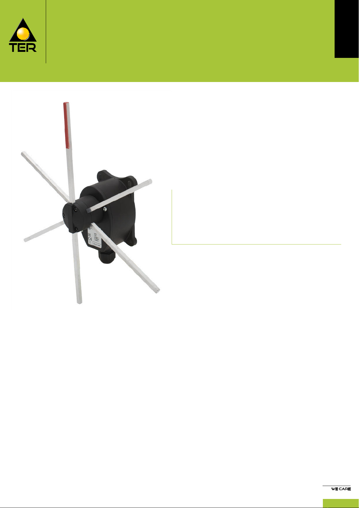
TER TANGO Quick setup guide

259
TANGO
Position limit switch
FEATURES
Modern design and overall dimensions studied to facilitate
installation and maintenance operations.
Rods with 4 maintained positions every 60°.
Positive opening NC contacts for safety functions.
Mechanical life of switches: 1 million operations.
Operation frequency: 3600 operations / hour max.
Extreme temperature resistance: -25°C to +70°C.
Enclosure and head in thermoplastic material (nylon
technopolymers to guarantee long life-cycle and constant
performance.
All materials and components used are wear resistant and
guarantee protection of the unit against water and dust.
OPTIONS
Slow action switches with 1NC or 1NO contacts.
Available with 2, 3 or 4 switches and different rod lengths.
CERTIFICATIONS
TANGO
5
Cross position limit switches designed for controlling
the movement of overhead travelling cranes, hoists and
complex machine tools.
Tango has rods with maintained positions every 60°.
circumstances can their description have a contractual value.

TANGO
5
260
CERTIFICATIONS
Conformity to Community Directives 2014/35/UE Low Voltage Directive
2006/42/CE Machinery Directive
Conformity to CE Standards
EN 60204-1 Safety of machinery - Electrical equipment of machines
EN 60947-1 Low-voltage switchgear and controlgear
EN 60947-5-1 Low-voltage switchgear and controlgear - Control circuit devices and switching
elements - Electromechanical control circuit devices
EN 60529 Degrees of protection provided by enclosures
Markings and homologations C
GENERAL TECHNICAL SPECIFICATIONS
Ambient temperature Storage -40°C/+70°C
Operational -25°C/+70°C
IP protection degree IP 65
Insulation category Class II
Operation frequency 3600 operations/hour max
Cable entry Cable clamp M20
TECHNICAL SPECIFICATIONS OF THE MICROSWITCHES
Code PRSL1000PI PRSL1001PI
Utilisation category AC 15
Rated operational current 3 A
Rated operational voltage 250 Vac
Rated thermal current 10 A
Rated insulation voltage 500 Vac
Mechanical life 1x10⁶operations
Connections Screw-type terminal
Wires 1x2.5 mm2, 2x1.5 mm2
(UL - (c)UL: use 60°C or 75°C copper (CU) conductor and wire 16-18 AWG)
Tightening torque 0.6 Nm
Microswitch type Double break, slow action Double break, slow action
Contacts 1NO
1NC
(All NC contacts are of the positive opening
operation type )
Scheme
13
14
11
12
Markings and homologations CX

TANGO
5
261
OVERALL DIMENSIONS (mm)
70
112
6
76.3
60°
60°
62 29.9
83.3
77.3
31.5
6
8
58
103.3
98.830
100
200
100
54
6.2
58
891.9 11.86
12.4
Ø6.2
MAXIMUM ACTUATING DIMENSIONS
Rods with 4 maintained positions
Pre-travel angle for rotation contact operation: 34°
Maximum rotation angle for each maintained position: 60°
Average angle for the mechanical tripping: 30°
Maintained positions each: 60°
In order to ensure proper operations, the dimensions shall not be increased; anyhow, they can be decreased, taking into account
that the closer the impact point is to the center of the head, the higher the impact and the mechanical wear of rod and shaft are.
30°
Rod length
300 mm
200 mm
250 mm
150 mm rod
125 mm rod
100 mm rod
Actuating point 60 mm
Actuating point 93 mm
Actuating point 76 mm

TANGO
5
262
EXPLODED DRAWING
1
2
3
4
5
6
7
8
9
10
11
12
13
14
15
16
17
18
19
20
21
22
23
24
25

TANGO
5
263
LIMIT SWITCHES
The limit switches are equipped with 1NC slow action switches PRSL1001PI
11
12
.
No. of switches
PRSL1001PI Actuating travel Rod length Code
2
300 mm PF48020001
250 mm PF48020005
200 mm PF48020006
3300 mm PF48030001
4
300 mm PF48040001
250 mm PF48040006
200 mm PF48040007

TANGO
5
264
ASSEMBLY DRAWING
A1
A1
A1
A2
A2
A3

TANGO
5
265
COMPONENTS
Accessories
Ref. Drawing Description Code
A1
Rod 6x6x200 mm PRTO3006PE
Rod 6x6x250 mm PRTO3011PE
Rod 6x6x300 mm PRTO3012PE
A3 Cable clamp M20 PRPS0064PE
Switches
Ref. Drawing Description Scheme Code
A2
1NO switch
13
14
PRSL1000PI
1NC switch
11
12
PRSL1001PI

TANGO
5
266
USE AND MAINTENANCE INSTRUCTIONS
The Tango limit switch is an electromechanical device for low
voltage control circuits (EN 60947-1, EN 60947-5-1) for use as
electric equipment on machines (EN 60204-1) in compliance with
the essential requisites of the Low Voltage Directive 2014/35/UE
and the Machine Directive 2006/42/CE.
The limit switch is designed for use in industrial environments
with even very severe climatic conditions (working
temperatures from -25°C to +70°C and is suitable for use
in tropical environments). The equipment is not suitable for
use in environments with a potentially explosive atmosphere,
in the presence of corrosive agents or high percentage of
sodium chloride (saline mist). Contact with oil, acids and
solvents may damage the equipment; avoid using them
for cleaning. The limit switches is not suitable for use in
environments with a potentially explosive atmosphere.
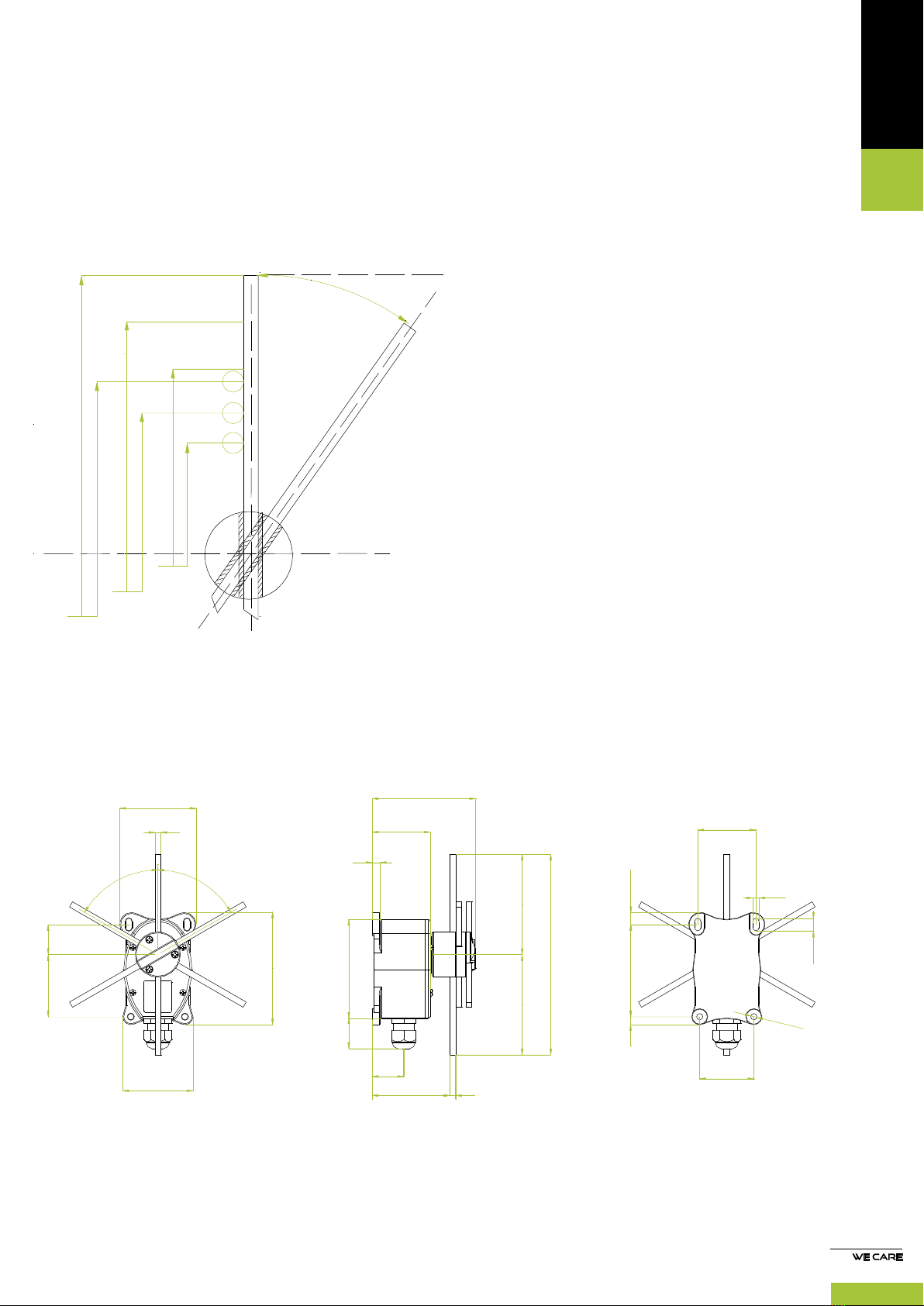
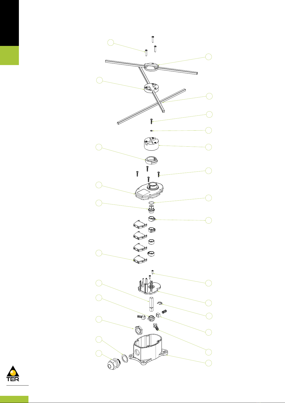
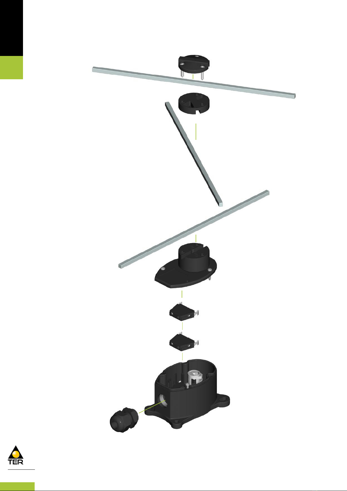
The Tango limit switch must be fastened through the holes
on the side of the case (12)*; in particular the top holes
are slots to facilitate fastening and adjustment of the limit
switch, which must be suitably position to ensure correct
impact on the drive rods (24). To prevent malfunctions or
problems; examine the technical documentation to view the
recommended impact points.
Turn the closing screws (1) and loosen the closure of the
rod holder (25, 21, 2), then you can move the rods to adjust
them; afterwards, tighten the closing screws (1) with a force
of 100cN m to ensure secure fastening of the rod holder.
We recommend adjusting the impact point of the rods (24)
by adjusting the fastening of the entire limit switch and not
simply moving the rods.
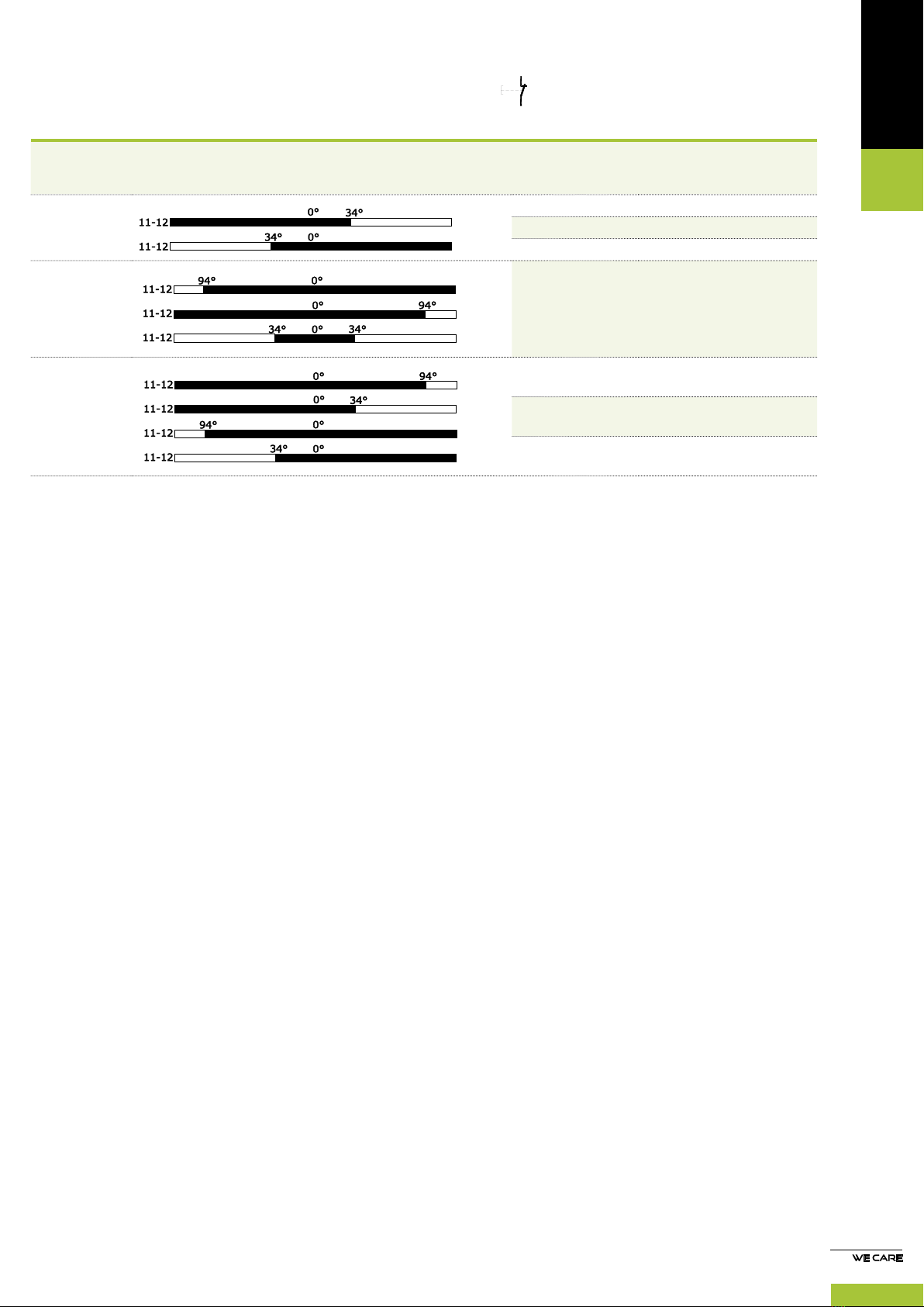
The switches (6) of the Tango are designed for the auxiliary
control of contacts or electromagnetic charges in general
(utilization category AC-15 in accordance with EN 60947-5-
1). The switches (6) have contacts with positive mechanical
opening operation (EN 60947-5-1). Do not connect more
than one phase for the switches (6). Never oil or grease the
switches (6).
To facilitate wiring the switches (6) the limit switches can
be removed from the case (12); after wiring, the switches (6)
must be replaced correctly in the case (12), then assemble the
cover (4) and tighten the screws (23) with a minimum force of
100cN m.
Installation of the limit switches should be done by
competent, trained personnel. The electric wiring must be
compliance with the regulations in force.
Before performing installation and maintenance of the limit
switches, disconnect the machine from the power mains.
Operations for installation and correct wiring of limit switch
- Fasten the limit switch securely to prevent malfunctions
during use of the device; to fasten it, use the holes on the
sides of the case (12); fasten the limit switch so that the
drive rods (24) function correctly, by examining the technical
documentation to identify the recommended point of impact;
adjust the rods (24), by turning the closing screws (1) on the
relative rod holder elements (25, 21, 2). Afterwards, tighten the
screws (1) with a force of 100 cNm.
- Introduce the multi-pole wire in the limit switch through
the wire clamp (11), strip the multi-pole cable for a length
- Wire the switches (6) as shown in the wiring diagrams on
each (6) (tighten the terminal screws with a torque of 0.6 Nm
(5.3 lbs/inch); insertability of wires into the switch terminals
equal to 2x1.5mm2– 1x2.5 mm2(UL (c)UL: use 60°C or 75°C
copper (CU) conductors)).
- After wiring tighten the wire in the wire clamp (11).
- Close the limit switch with its cover (4) with the closing
screws (20); applying a force of at least 100cN m.
Operations of routine maintenance
- Check the correct tightening of the closing screws (20) on
the cover (4).
- Check the conditions of the wires on the switches (6) (if
necessary, tighten the screws on the terminals).
- Tighten the multi-pole wire in the wire clamp (12).
- Check the conditions of the complete limit switch (25, 24, 21,
12, 4, 2).
- Check the fastening of the limit switch.
Any change to parts of the limit switch will invalidate the
the warranty null and void. In case of replacement of any part,
use only original replacements.
TER is not liable for damages caused by improper use of the
device and installation which is not made correctly.
*Please refer to the exploded drawing in the catalogue.
Table of contents
Other TER Industrial Equipment manuals
Popular Industrial Equipment manuals by other brands

Samuel Strapping Systems
Samuel Strapping Systems ISP BinderyMate 2 305 owner's manual

Paccar
Paccar BRADEN/GEARMATIC BG8A Installation maintenance and service manual

Jäger
Jäger Z80-H445.06 S5AW2/2 manual

ABB
ABB HT577282 Operation manual

ABB
ABB A150-M68 Operation manual

Wieland
Wieland SLC Series operating instructions

Dodge
Dodge HYDROIL TORQUE-ARM HXT325C Parts replacement manual

LUCOMA
LUCOMA RGK-10 Series Installation, operation and maintenance instructions

ABB
ABB CPS3200U product manual

werma
werma AndonWirelessBOX quick start guide

Siemens
Siemens SIMATIC NET SCALANCE W1750D Regulatory compliance and safety information guide

Dover
Dover OPW 301 Series Installation and maintenance instructions